Page 3051 of 4323
RA0997
SA0353
± SUSPENSION AND AXLEFRONT DIFFERENTIAL CARRIER
SA±47
3043 Author�: Date�:
2005 SEQUOIA (RM1146U)
21. DISASSEMBLE DIFFERENTIAL CASE ASSEMBLY
(a) Using a pin punch and hammer, remove the straight pin.
(b) Remove the pinion shaft, 2 pinion gears, pinion gear
thrust washers, side gears and side gear thrust washers
from the differential case.
22. REMOVE BEARINGS
Using a brass bar and hammer, remove the 2 bearings.
Page 3054 of 4323
SA0355
SST
0.3 ± 0.3 mm
(0.012 ± 0.012 in.)
SA23O±04
FA1121
F14731
FA1124
SA±50
± SUSPENSION AND AXLEFRONT DIFFERENTIAL CARRIER
3046 Author�: Date�:
2005 SEQUOIA (RM1146U)
REASSEMBLY
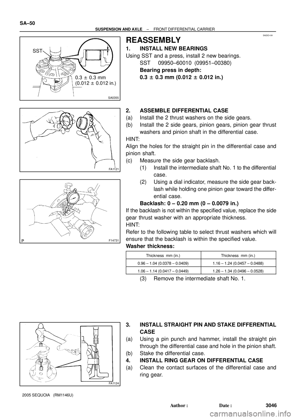
1. INSTALL NEW BEARINGS
Using SST and a press, install 2 new bearings.
SST 09950±60010 (09951±00380)
Bearing press in depth:
0.3 ± 0.3 mm (0.012 ± 0.012 in.)
2. ASSEMBLE DIFFERENTIAL CASE
(a) Install the 2 thrust washers on the side gears.
(b) Install the 2 side gears, pinion gears, pinion gear thrust
washers and pinion shaft in the differential case.
HINT:
Align the holes for the straight pin in the differential case and
pinion shaft.
(c) Measure the side gear backlash.
(1) Install the intermediate shaft No. 1 to the differential
case.
(2) Using a dial indicator, measure the side gear back-
lash while holding one pinion gear toward the differ-
ential case.
Backlash: 0 ± 0.20 mm (0 ± 0.0079 in.)
If the backlash is not within the specified value, replace the side
gear thrust washer with an appropriate thickness.
HINT:
Refer to the following table to select thrust washers which will
ensure that the backlash is within the specified value.
Washer thickness:
Thickness mm (in.)Thickness mm (in.)
0.96 ± 1.04 (0.0378 ± 0.0409)1.16 ± 1.24 (0.0457 ± 0.0488)
1.06 ± 1.14 (0.0417 ± 0.0449)1.26 ± 1.34 (0.0496 ± 0.0528)
(3) Remove the intermediate shaft No. 1.
3. INSTALL STRAIGHT PIN AND STAKE DIFFERENTIAL
CASE
(a) Using a pin punch and hammer, install the straight pin
through the differential case and hole in the pinion shaft.
(b) Stake the differential case.
4. INSTALL RING GEAR ON DIFFERENTIAL CASE
(a) Clean the contact surfaces of the differential case and
ring gear.
Page 3056 of 4323
R13376
SST
R13281
SST
Front bearing
outer race:Rear bearing
outer race:
R01197
SST
R11163
SST SA±52
± SUSPENSION AND AXLEFRONT DIFFERENTIAL CARRIER
3048 Author�: Date�:
2005 SEQUOIA (RM1146U)
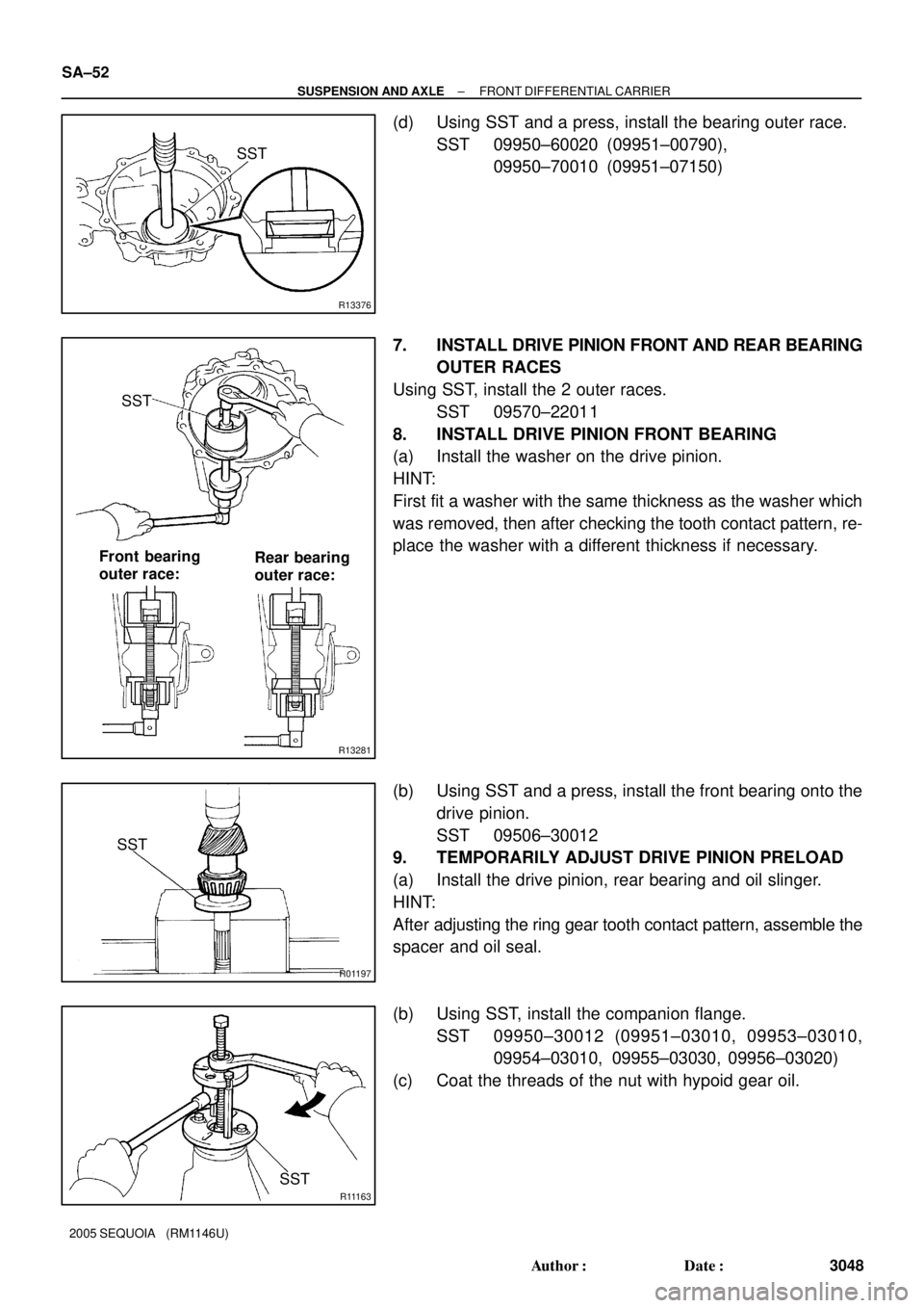
(d) Using SST and a press, install the bearing outer race.
SST 09950±60020 (09951±00790),
09950±70010 (09951±07150)
7. INSTALL DRIVE PINION FRONT AND REAR BEARING
OUTER RACES
Using SST, install the 2 outer races.
SST 09570±22011
8. INSTALL DRIVE PINION FRONT BEARING
(a) Install the washer on the drive pinion.
HINT:
First fit a washer with the same thickness as the washer which
was removed, then after checking the tooth contact pattern, re-
place the washer with a different thickness if necessary.
(b) Using SST and a press, install the front bearing onto the
drive pinion.
SST 09506±30012
9. TEMPORARILY ADJUST DRIVE PINION PRELOAD
(a) Install the drive pinion, rear bearing and oil slinger.
HINT:
After adjusting the ring gear tooth contact pattern, assemble the
spacer and oil seal.
(b) Using SST, install the companion flange.
SST 09950±30012 (09951±03010, 09953±03010,
09954±03010, 09955±03030, 09956±03020)
(c) Coat the threads of the nut with hypoid gear oil.
Page 3057 of 4323
SA2347
SST
SA2352
R12683
SST
± SUSPENSION AND AXLEFRONT DIFFERENTIAL CARRIER
SA±53
3049 Author�: Date�:
2005 SEQUOIA (RM1146U)
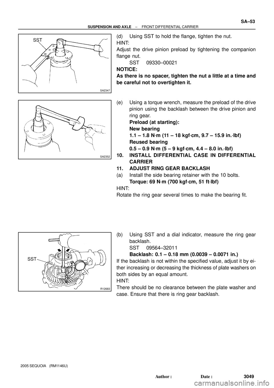
(d) Using SST to hold the flange, tighten the nut.
HINT:
Adjust the drive pinion preload by tightening the companion
flange nut.
SST 09330±00021
NOTICE:
As there is no spacer, tighten the nut a little at a time and
be careful not to overtighten it.
(e) Using a torque wrench, measure the preload of the drive
pinion using the backlash between the drive pinion and
ring gear.
Preload (at starting):
New bearing
1.1 ± 1.8 N´m (11 ± 18 kgf´cm, 9.7 ± 15.9 in.´lbf)
Reused bearing
0.5 ± 0.9 N´m (5 ± 9 kgf´cm, 4.4 ± 8.0 in.´lbf)
10. INSTALL DIFFERENTIAL CASE IN DIFFERENTIAL
CARRIER
11. ADJUST RING GEAR BACKLASH
(a) Install the side bearing retainer with the 10 bolts.
Torque: 69 N´m (700 kgf´cm, 51 ft´lbf)
HINT:
Rotate the ring gear several times to make the bearing fit.
(b) Using SST and a dial indicator, measure the ring gear
backlash.
SST 09564±32011
Backlash: 0.1 ± 0.18 mm (0.0039 ± 0.0071 in.)
If the backlash is not within the specified value, adjust it by ei-
ther increasing or decreasing the thickness of plate washers on
both sides by an equal amount.
HINT:
There should be no clearance between the plate washer and
case. Ensure that there is ring gear backlash.
Page 3058 of 4323
R13220
SA±54
± SUSPENSION AND AXLEFRONT DIFFERENTIAL CARRIER
3050 Author�: Date�:
2005 SEQUOIA (RM1146U)
Washer thickness:
Thickness mm (in.)Thickness mm (in.)Thickness mm (in.)
2.00 ± 2.02 (0.0787 ± 0.0795)2.27 ± 2.29 (0.0894 ± 0.0902)2.54 ± 2.56 (0.1000 ± 0.1008)
2.03 ± 2.05 (0.0799 ± 0.0807)2.30 ± 2.32 (0.0906 ± 0.0913)2.57 ± 2.59 (0.1012 ± 0.1020)
2.06 ± 2.08 (0.0811 ± 0.0819)2.33 ± 2.35 (0.0917 ± 0.0925)2.60 ± 2.62 (0.1024 ± 0.1031)
2.09 ± 2.11 (0.0823 ± 0.0831)2.36 ± 2.38 (0.0929 ± 0.0937)2.63 ± 2.65 (0.1035 ± 0.1043)
2.12 ± 2.14 (0.0835 ± 0.0843)2.39 ± 2.41 (0.0941 ± 0.0949)2.66 ± 2.68 (0.1047 ± 0.1055)
2.15 ± 2.17 (0.0846 ± 0.0854)2.42 ± 2.44 (0.0953 ± 0.0961)2.69 ± 2.71 (0.1059 ± 0.1067)
2.18 ± 2.20 (0.0858 ± 0.0866)2.45 ± 2.47 (0.0965 ± 0.0972)2.72 ± 2.74 (0.1071 ± 0.1079)
2.21 ± 2.23 (0.0870 ± 0.0878)2.48 ± 2.50 (0.0976 ± 0.0984)2.75 ± 2.77 (0.1083 ± 0.1091)
2.24 ± 2.26 (0.0882 ± 0.0890)2.51 ± 2.53 (0.0988 ± 0.0996)2.78 ± 2.80 (0.1094 ± 0.1102)
12. MEASURE TOTAL PRELOAD
Using a torque wrench, measure the preload with the teeth of
the drive pinion and ring gear in contact.
Total preload (at starting):
Drive pinion preload plus 0.4 ± 0.6 N´m (4 ± 6 kgf´cm,
3.5 ± 5.2 in.´lbf)
13. INSPECT TOOTH CONTACT BETWEEN RING GEAR
AND DRIVE PINION
(a) Remove the 10 bolts, side bearing retainer and differen-
tial case.
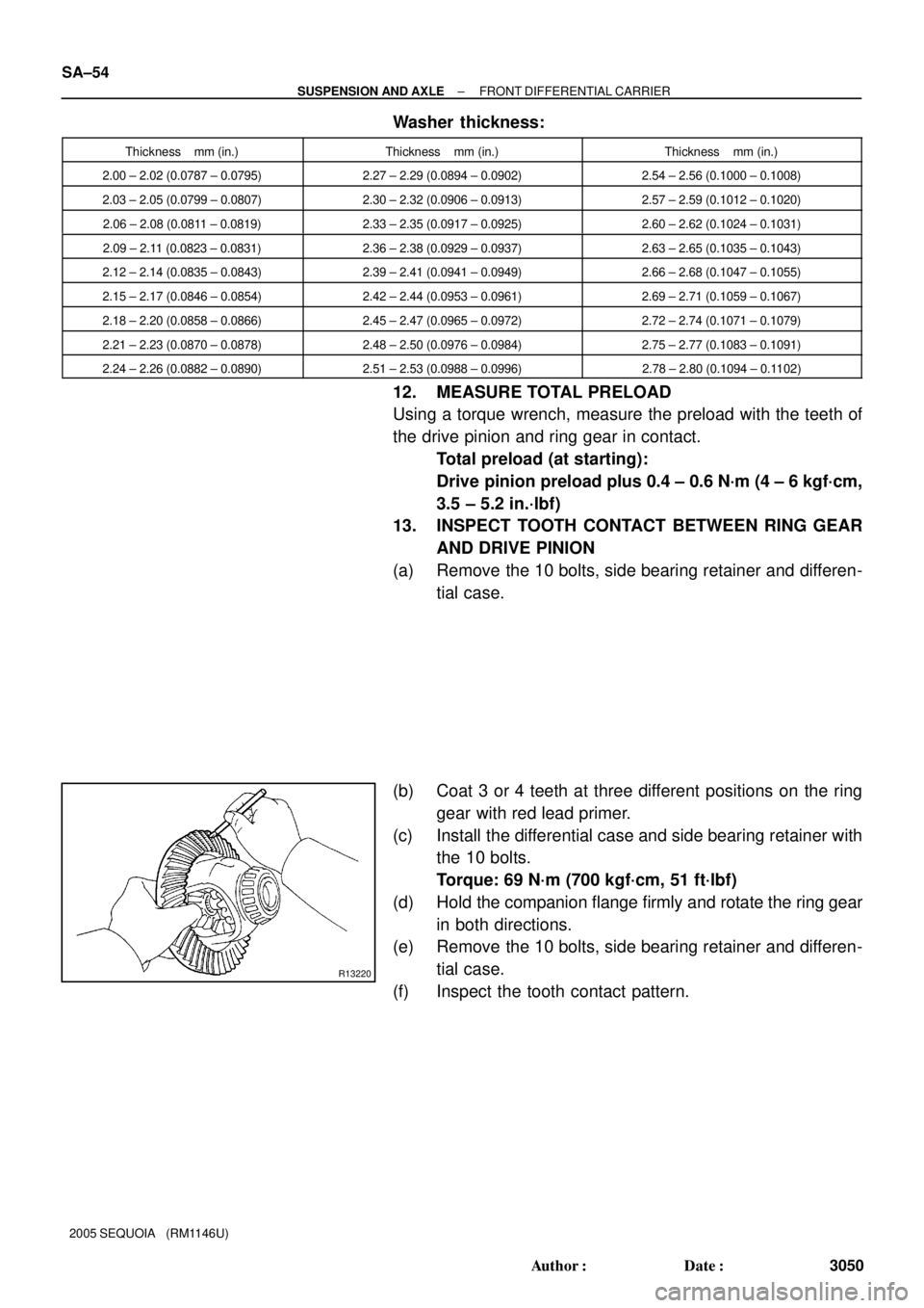
(b) Coat 3 or 4 teeth at three different positions on the ring
gear with red lead primer.
(c) Install the differential case and side bearing retainer with
the 10 bolts.
Torque: 69 N´m (700 kgf´cm, 51 ft´lbf)
(d) Hold the companion flange firmly and rotate the ring gear
in both directions.
(e) Remove the 10 bolts, side bearing retainer and differen-
tial case.
(f) Inspect the tooth contact pattern.
Page 3059 of 4323
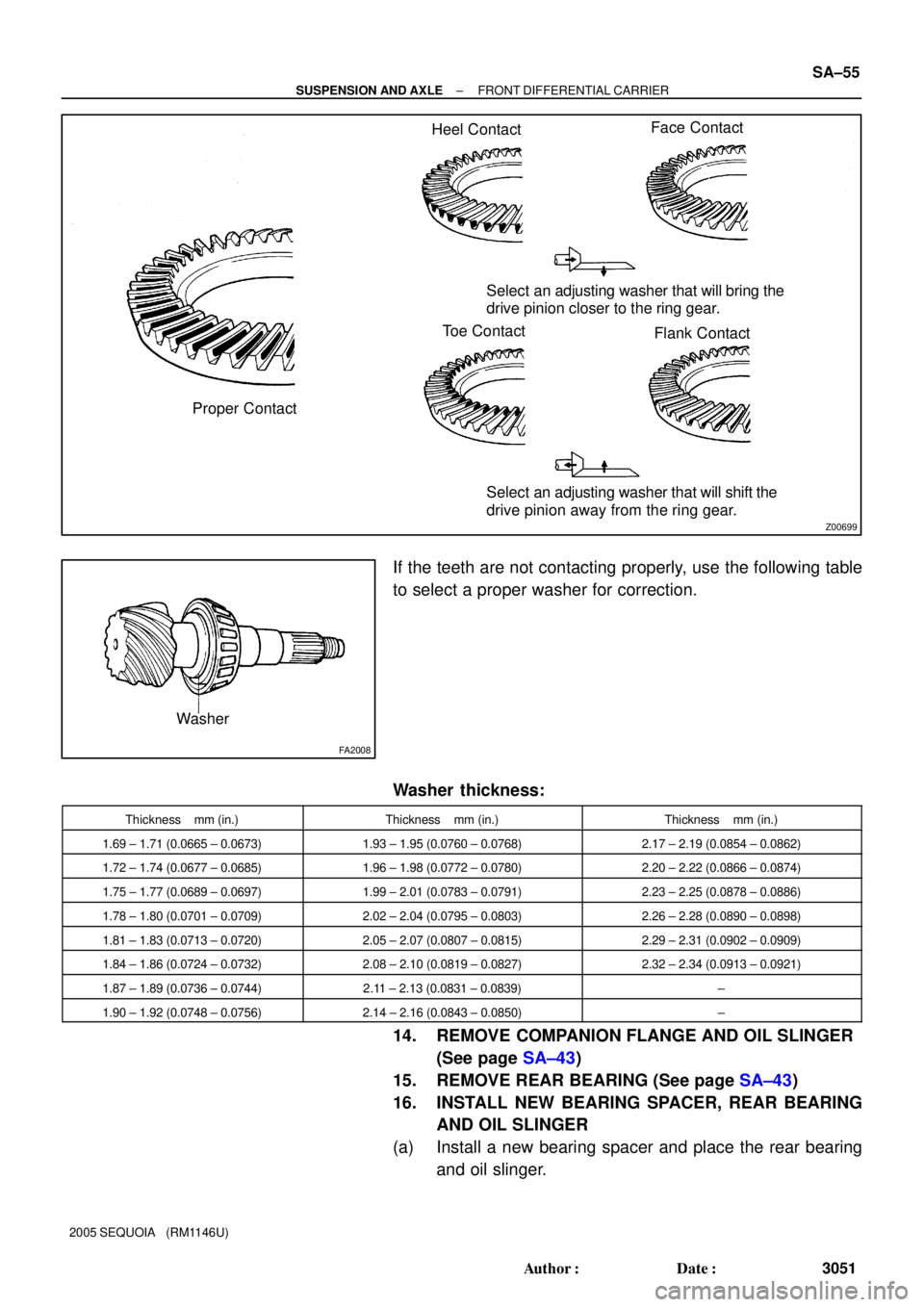
Z00699
Heel ContactFace Contact
Proper ContactSelect an adjusting washer that will bring the
drive pinion closer to the ring gear.
Toe Contact
Flank Contact
Select an adjusting washer that will shift the
drive pinion away from the ring gear.
FA2008
Washer
± SUSPENSION AND AXLEFRONT DIFFERENTIAL CARRIER
SA±55
3051 Author�: Date�:
2005 SEQUOIA (RM1146U)
If the teeth are not contacting properly, use the following table
to select a proper washer for correction.
Washer thickness:
Thickness mm (in.)Thickness mm (in.)Thickness mm (in.)
1.69 ± 1.71 (0.0665 ± 0.0673)1.93 ± 1.95 (0.0760 ± 0.0768)2.17 ± 2.19 (0.0854 ± 0.0862)
1.72 ± 1.74 (0.0677 ± 0.0685)1.96 ± 1.98 (0.0772 ± 0.0780)2.20 ± 2.22 (0.0866 ± 0.0874)
1.75 ± 1.77 (0.0689 ± 0.0697)1.99 ± 2.01 (0.0783 ± 0.0791)2.23 ± 2.25 (0.0878 ± 0.0886)
1.78 ± 1.80 (0.0701 ± 0.0709)2.02 ± 2.04 (0.0795 ± 0.0803)2.26 ± 2.28 (0.0890 ± 0.0898)
1.81 ± 1.83 (0.0713 ± 0.0720)2.05 ± 2.07 (0.0807 ± 0.0815)2.29 ± 2.31 (0.0902 ± 0.0909)
1.84 ± 1.86 (0.0724 ± 0.0732)2.08 ± 2.10 (0.0819 ± 0.0827)2.32 ± 2.34 (0.0913 ± 0.0921)
1.87 ± 1.89 (0.0736 ± 0.0744)2.11 ± 2.13 (0.0831 ± 0.0839)±
1.90 ± 1.92 (0.0748 ± 0.0756)2.14 ± 2.16 (0.0843 ± 0.0850)±
14. REMOVE COMPANION FLANGE AND OIL SLINGER
(See page SA±43)
15. REMOVE REAR BEARING (See page SA±43)
16. INSTALL NEW BEARING SPACER, REAR BEARING
AND OIL SLINGER
(a) Install a new bearing spacer and place the rear bearing
and oil slinger.
Page 3060 of 4323
R11163SST
R13417
SST
4.5 ± 0.3 mm
(0.177 ± 0.012 in.)
SA2351
SST
SA2352
SA±56
± SUSPENSION AND AXLEFRONT DIFFERENTIAL CARRIER
3052 Author�: Date�:
2005 SEQUOIA (RM1146U)
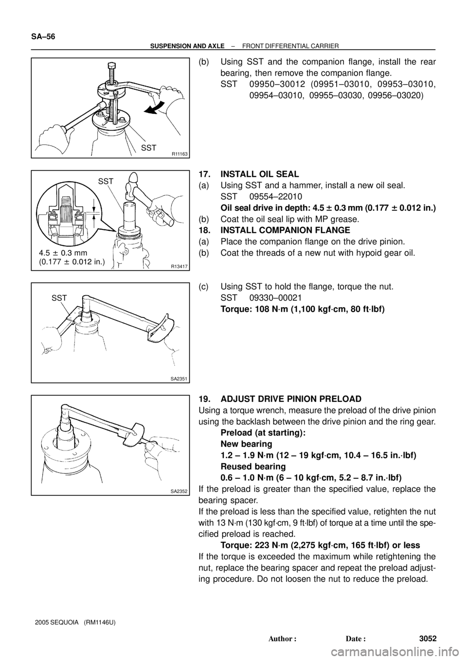
(b) Using SST and the companion flange, install the rear
bearing, then remove the companion flange.
SST 09950±30012 (09951±03010, 09953±03010,
09954±03010, 09955±03030, 09956±03020)
17. INSTALL OIL SEAL
(a) Using SST and a hammer, install a new oil seal.
SST 09554±22010
Oil seal drive in depth: 4.5 ± 0.3 mm (0.177 ± 0.012 in.)
(b) Coat the oil seal lip with MP grease.
18. INSTALL COMPANION FLANGE
(a) Place the companion flange on the drive pinion.
(b) Coat the threads of a new nut with hypoid gear oil.
(c) Using SST to hold the flange, torque the nut.
SST 09330±00021
Torque: 108 N´m (1,100 kgf´cm, 80 ft´lbf)
19. ADJUST DRIVE PINION PRELOAD
Using a torque wrench, measure the preload of the drive pinion
using the backlash between the drive pinion and the ring gear.
Preload (at starting):
New bearing
1.2 ± 1.9 N´m (12 ± 19 kgf´cm, 10.4 ± 16.5 in.´lbf)
Reused bearing
0.6 ± 1.0 N´m (6 ± 10 kgf´cm, 5.2 ± 8.7 in.´lbf)
If the preload is greater than the specified value, replace the
bearing spacer.
If the preload is less than the specified value, retighten the nut
with 13 N´m (130 kgf´cm, 9 ft´lbf) of torque at a time until the spe-
cified preload is reached.
Torque: 223 N´m (2,275 kgf´cm, 165 ft´lbf) or less
If the torque is exceeded the maximum while retightening the
nut, replace the bearing spacer and repeat the preload adjust-
ing procedure. Do not loosen the nut to reduce the preload.
Page 3061 of 4323
R13200
FIPG
R13416
SST
R13415
± SUSPENSION AND AXLEFRONT DIFFERENTIAL CARRIER
SA±57
3053 Author�: Date�:
2005 SEQUOIA (RM1146U)
20. INSTALL DIFFERENTIAL CASE
21. INSTALL SIDE BEARING RETAINER
(a) Remove any old FIPG material and be careful not to drop
oil on the contact surfaces of the differential carrier and
side bearing retainer.
(b) Clean both installation surfaces with gasoline or alcohol.
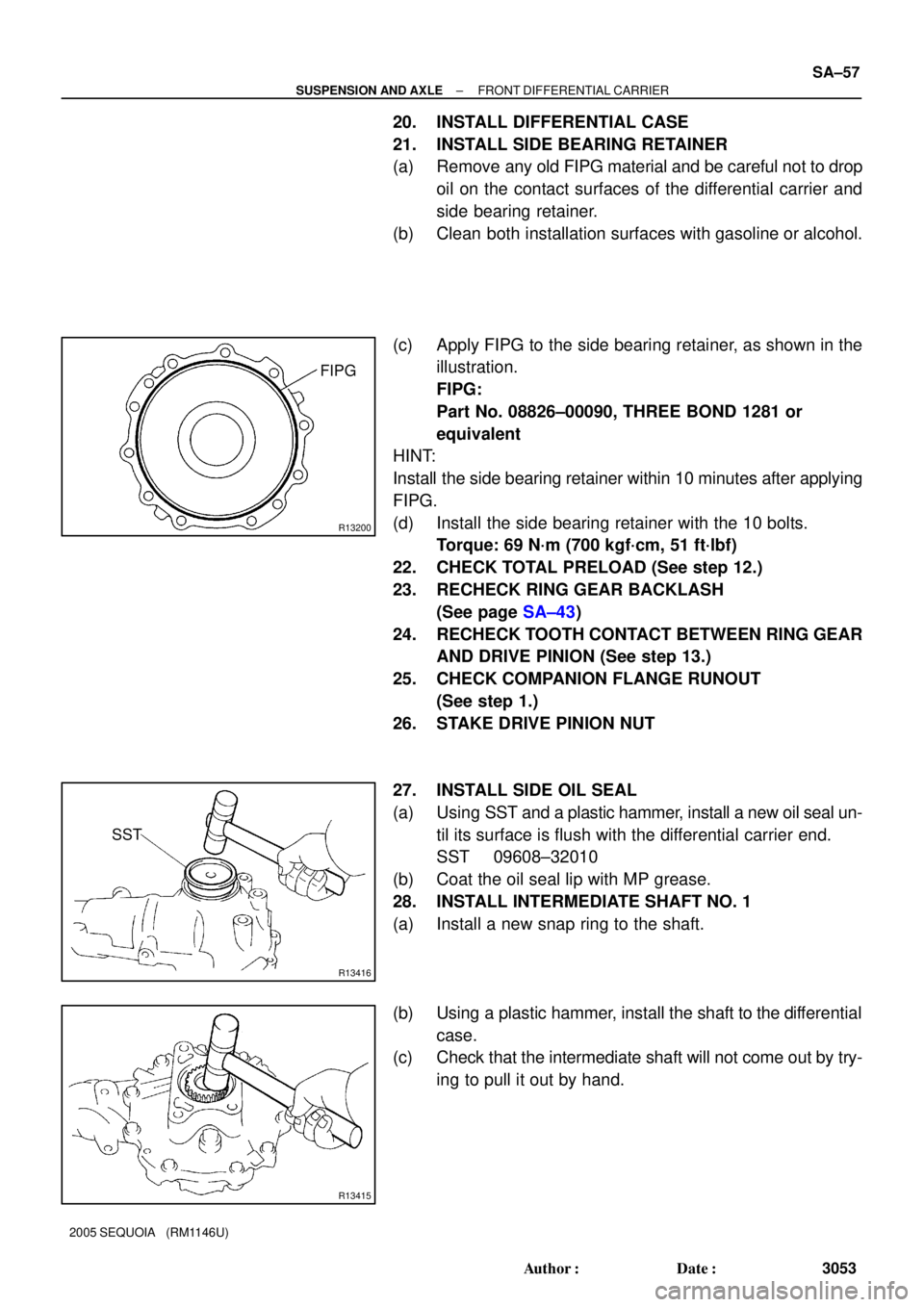
(c) Apply FIPG to the side bearing retainer, as shown in the
illustration.
FIPG:
Part No. 08826±00090, THREE BOND 1281 or
equivalent
HINT:
Install the side bearing retainer within 10 minutes after applying
FIPG.
(d) Install the side bearing retainer with the 10 bolts.
Torque: 69 N´m (700 kgf´cm, 51 ft´lbf)
22. CHECK TOTAL PRELOAD (See step 12.)
23. RECHECK RING GEAR BACKLASH
(See page SA±43)
24. RECHECK TOOTH CONTACT BETWEEN RING GEAR
AND DRIVE PINION (See step 13.)
25. CHECK COMPANION FLANGE RUNOUT
(See step 1.)
26. STAKE DRIVE PINION NUT
27. INSTALL SIDE OIL SEAL
(a) Using SST and a plastic hammer, install a new oil seal un-
til its surface is flush with the differential carrier end.
SST 09608±32010
(b) Coat the oil seal lip with MP grease.
28. INSTALL INTERMEDIATE SHAFT NO. 1
(a) Install a new snap ring to the shaft.
(b) Using a plastic hammer, install the shaft to the differential
case.
(c) Check that the intermediate shaft will not come out by try-
ing to pull it out by hand.