Page 3117 of 4323

SA24F±03
R04321
R04322
R04463
± SUSPENSION AND AXLEREAR DIFFERENTIAL CARRIER
SA±113
3109 Author�: Date�:
2005 SEQUOIA (RM1146U)
DISASSEMBLY
1. CHECK COMPANION FLANGE RUNOU")
W00493
35 mm (1.38 in.)
SA24F±03
R04321
R04322
R04463
± SUSPENSION AND AXLEREAR DIFFERENTIAL CARRIER
SA±113
3109 Author�: Date�:
2005 SEQUOIA (RM1146U)
DISASSEMBLY
1. CHECK COMPANION FLANGE RUNOUT
Using a dial indicator, measure the vertical and lateral runout of
the companion flange.
Maximum: runout: 0.09 mm (0.0035 in.)
If the runout exceeds the maximum, replace the companion
flange.
2. CHECK RING GEAR RUNOUT
Using a dial indicator, measure the ring gear runout.
Maximum runout: 0.05 mm (0.0020 in.)
If the runout exceeds the maximum, replace the ring gear.
3. CHECK RING GEAR BACKLASH
Using a dial indicator, while holding the companion flange, mea-
sure the ring gear backlash.
Backlash: 0.13 ± 0.18 mm (0.0051 ± 0.0071 in.)
HINT:
Measure at 3 or more positions around the circumference of the
ring gear.
If the backlash is not within the specified value, adjust the side
bearing preload or repair as necessary.
4. CHECK TOOTH CONTACT BETWEEN RING GEAR
AND DRIVE PINION (See page SA±119)
5. CHECK SIDE GEAR BACKLASH
Using a dial indicator, measure the side gear backlash while
holding one pinion gear toward the case.
Backlash: 0.05 ± 0.20 mm (0.0020 ± 0.0079 in.)
If the backlash is not within the specified value, replace the side
gear thrust washer of the different thickness (See page
SA±119).
Page 3118 of 4323

F14485
SST
F14484
SST
SA±114
± SUSPENSION AND AXLEREAR DIFFERENTIAL CARRIER
3110 Author�: Date�:
2005 SEQUOIA (RM1146U)
6. MEASURE DRIVE PINION PRELOAD
Using a torqu")
SA2352
F14486
40 mm
(1.57 in.)
F14485
SST
F14484
SST
SA±114
± SUSPENSION AND AXLEREAR DIFFERENTIAL CARRIER
3110 Author�: Date�:
2005 SEQUOIA (RM1146U)
6. MEASURE DRIVE PINION PRELOAD
Using a torque wrench, measure the preload of the drive pinion
using the backlash between the drive pinion and ring gear.
Preload (at starting):
0.8 ± 1.1 N´m (8 ± 11 kgf´cm, 7.0 ± 9.7 in.´lbf)
7. CHECK TOTAL PRELOAD
Using a torque wrench, measure the total preload with the teeth
of the drive pinion and ring gear in contact.
Total preload (at starting):
Drive pinion preload plus 0.4 ± 0.6 N´m (4 ± 6 kgf´cm,
3.5 ± 5.2 in.´lbf)
If necessary, disassemble and inspect the differential.
8. REMOVE COMPANION FLANGE
(a) Using a chisel and hammer, unstake the staked part of the
nut.
(b) 2WD:
Remove the companion flange nut.
(1) Using a torx® soket (E8), remove the stud bolt and
loosen the 3 bolts so that the heads come out 40
mm (1.57 in.).
(2) Set the SST and install the 3 nuts to the companion
flange.
SST 09213±58013
(3) Install the other SST to the set SST to hold the com-
panion flange, and remove the nut.
SST 09330±00021
(4) Remove the 3 nuts, stud bolts and SST from the
companion flange.
Page 3119 of 4323
SA2349
SST
R11391SST
SA2348
SST
Z00641
SST
R04324
Matchmarks
± SUSPENSION AND AXLEREAR DIFFERENTIAL CARRIER
SA±115
3111 Author�: Date�:
2005 SEQUOIA (RM1146U)
(c) 4WD:
Using SST to hold the flange, remove the nut.
SST 09330±00021
(d) Using SST, remove the companion flange.
SST 09950±30012 (09951±03010, 09953±03010,
09954±03010, 09955±03030, 09956±03050)
9. REMOVE FRONT OIL SEAL
Using SST, remove the oil seal from the differential carrier.
SST 09308±10010
10. REMOVE FRONT BEARING AND BEARING SPACER
(a) Using SST, remove the bearing from the drive pinion.
SST 09556±22010
If the front bearing is damaged or worn, replace the front bear-
ing.
(b) Remove the 2 washers and bearing spacer.
11. REMOVE DIFFERENTIAL CASE
(a) Place matchmarks on the bearing cap and differential car-
rier.
(b) Remove the 4 bolts and bearing cap.
Page 3120 of 4323

(c) Using SST and a plastic hammer, re")
R04325
SST
R02482
SST
R04326
Front: Rear:
R04327
Matchmarks SA±116
± SUSPENSION AND AXLEREAR DIFFERENTIAL CARRIER
3112 Author�: Date�:
2005 SEQUOIA (RM1146U)
(c) Using SST and a plastic hammer, remove the 2 side bear-
ing plate washers.
SST 09504±22012
HINT:
Measure the plate washer thickness and note it down.
(d) Remove the differential case with the bearing outer races
from the carrier.
HINT:
Tag the bearing outer races to show the location for reassem-
bling.
12. REMOVE DRIVE PINION FROM DIFFERENTIAL CAR-
RIER
Remove the drive pinion with the rear bearing.
13. REMOVE DRIVE PINION REAR BEARING
Using SST and a press, remove the bearing from the drive pin-
ion.
SST 09950±00020
HINT:
If the drive pinion or ring gear is damaged, replace them as a
set.
14. REMOVE FRONT AND REAR BEARING OUTER
RACES AND ADJUSTING WASHER
NOTICE:
Do not remove the outer races except when replacing the
bearings.
Using a brass bar and hammer, remove the outer races and ad-
justing washer from the carrier.
HINT:
Measure the adjusting washer thickness and note it down.
15. REMOVE RING GEAR
(a) Place matchmarks on the ring gear and differential case.
(b) Remove the 12 ring gear set bolts.
(c) Using a plastic hammer, tap on the ring gear to separate
it from the differential case.
16. CHECK DIFFERENTIAL CASE RUNOUT
(a) Install the differential case in the differential carrier (See
page SA±119).
Page 3121 of 4323
R04328
R12920
SST
SST
RA0997
± SUSPENSION AND AXLEREAR DIFFERENTIAL CARRIER
SA±117
3113 Author�: Date�:
2005 SEQUOIA (RM1146U)
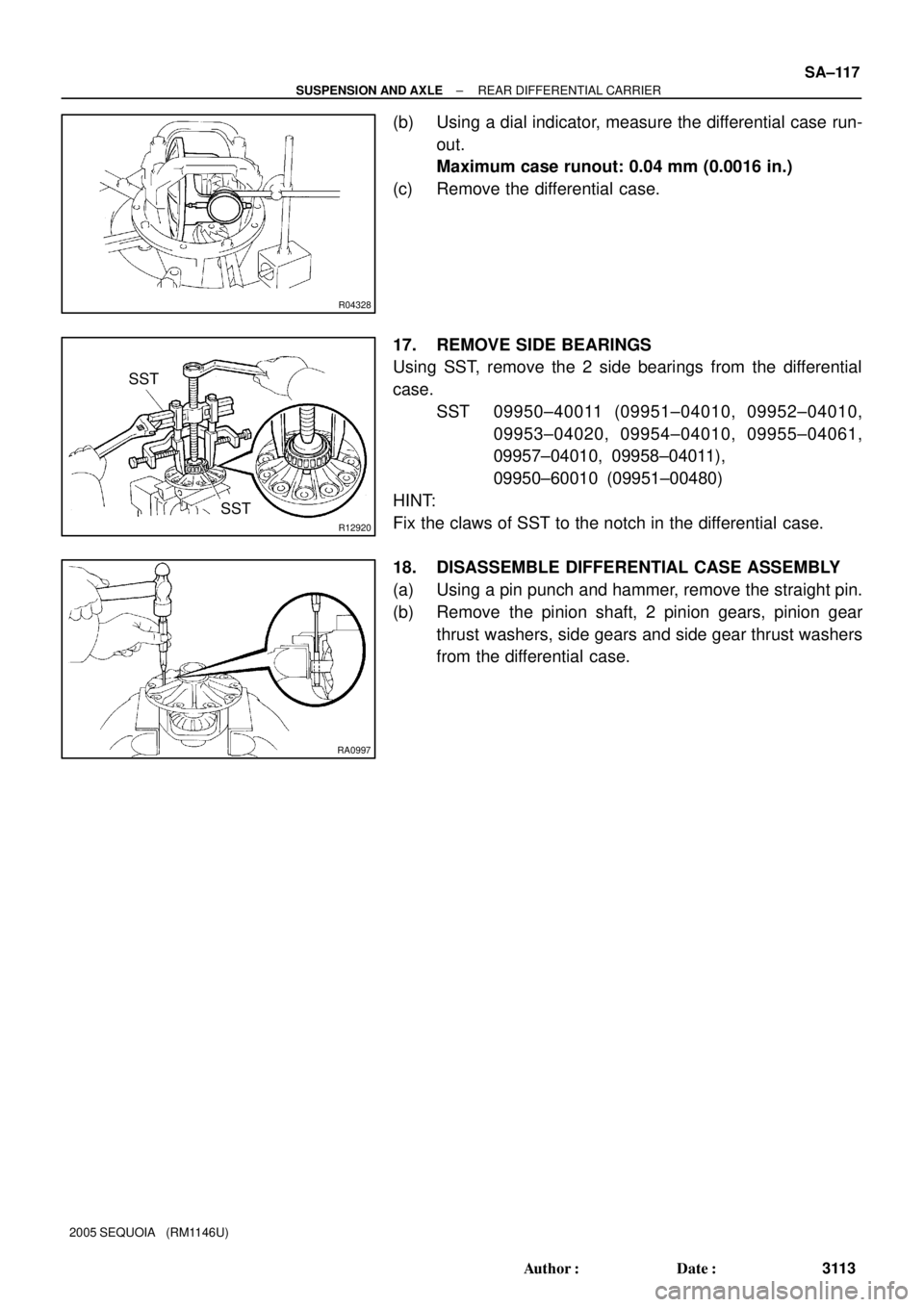
(b) Using a dial indicator, measure the differential case run-
out.
Maximum case runout: 0.04 mm (0.0016 in.)
(c) Remove the differential case.
17. REMOVE SIDE BEARINGS
Using SST, remove the 2 side bearings from the differential
case.
SST 09950±40011 (09951±04010, 09952±04010,
09953±04020, 09954±04010, 09955±04061,
09957±04010, 09958±04011),
09950±60010 (09951±00480)
HINT:
Fix the claws of SST to the notch in the differential case.
18. DISASSEMBLE DIFFERENTIAL CASE ASSEMBLY
(a) Using a pin punch and hammer, remove the straight pin.
(b) Remove the pinion shaft, 2 pinion gears, pinion gear
thrust washers, side gears and side gear thrust washers
from the differential case.
Page 3123 of 4323

REASSEMBLY
1. ASSEMBLE DIFFERENTIAL CASE
(a)")
FA1121
SA24G±03
FA1123
FA1124
R13423
SST
SST
SSTSST
± SUSPENSION AND AXLEREAR DIFFERENTIAL CARRIER
SA±119
3115 Author�: Date�:
2005 SEQUOIA (RM1146U)
REASSEMBLY
1. ASSEMBLE DIFFERENTIAL CASE
(a) Install the 2 thrust washers to the side gears.
(b) Install the 2 side gears with the thrust washers, 2 pinion
gears, 2 pinion gear thrust washers and pinion shaft.
HINT:
Align the holes for the straight pin in the differential case and
pinion shaft.
(c) Using a dial indicator, measure the side gear backlash
while holding one pinion gear toward the differential case.
Backlash: 0.05 ± 0.20 mm (0.0020 ± 0.0079 in.)
If the backlash is not within the specified value, replace the side
gear thrust washer with an appropriate thickness.
HINT:
Refer to the following table to select thrust washers which will
ensure that the backlash is within the specified value.
Washer thickness:
Thickness mm (in.)Thickness mm (in.)
1.50 (0.0590)1.75 (0.0689)
1.55 (0.0610)1.80 (0.0709)
1.60 (0.0630)1.85 (0.0728)
1.65 (0.0650)1.90 (0.0748)
1.70 (0.0669)±
(d) Using a pin punch and hammer, install the straight pin
through the holes in the differential case and pinion shaft.
(e) Using a chisel and hammer, stake the outside of the differ-
ential case pin hole.
2. INSTALL SIDE BEARINGS
Using SST and a press, install the 2 side bearings into the differ-
ential case.
SST 09950±60010 (09951±00510),
09950±60020 (09950±00680),
09950±70010 (09951±07150)
3. INSTALL RING GEAR ON DIFFERENTIAL CASE
(a) Clean the contact surfaces of the differential case and
ring gear.
Page 3124 of 4323

(b) Heat the ring gear to abo")
SA1143
Boiling Water
R04332
Matchmarks
Thread Lock
R04334
R04335
SST SA±120
± SUSPENSION AND AXLEREAR DIFFERENTIAL CARRIER
3116 Author�: Date�:
2005 SEQUOIA (RM1146U)
(b) Heat the ring gear to about 100°C (212°F) in boiling wa-
ter.
(c) Carefully take the ring gear out of the boiling water.
(d) After the moisture on the ring gear has completely evapo-
rated, quickly install the ring gear to the differential case.
HINT:
Align the matchmarks on the ring gear and differential case.
(e) After the ring gear has cooled sufficiently, torque the set
bolts to which thread lock has been applied.
Thread lock:
Part No. 08833±00100, THREE BOND 1360K or equiv-
alent.
Torque: 125 N´m (1,270 kgf´cm, 92 ft´lbf)
4. INSPECT RING GEAR RUNOUT
(a) Install the differential case into the carrier and install the
plate washers to where there is no play in the bearing
(See step 8.).
(b) Install the bearing cap (See step 11.).
(c) Using a dial indicator, measure the runout of the ring gear.
(d) Remove the bearing caps and differential case.
Maximum runout: 0.05 mm (0.0020 in.)
5. INSTALL DRIVE PINION BEARING OUTER RACES
AND ADJUSTING WASHER
(a) Using SST and a press, install a new front bearing outer
race to the carrier.
SST 09950±60020 (09951±00710),
09950±70010 (09951±07150)
(b) Using SST and a press, install a new adjusting washer
and a new rear bearing outer race to the carrier.
SST 09950±60020 (09951±00910),
09950±70010 (09951±07150)
Page 3125 of 4323

F14485
SST
± SUSPENSION AND AXLEREAR DIFFERENTIAL CARRIER
SA±121
3117 Author�: Date�:
2005 SEQUOIA (RM1146U)
HINT:
First fit a washer with the same thi")
R00055
SST
R11163SST
F14486
40 mm
(1.57 in.)
F14485
SST
± SUSPENSION AND AXLEREAR DIFFERENTIAL CARRIER
SA±121
3117 Author�: Date�:
2005 SEQUOIA (RM1146U)
HINT:
First fit a washer with the same thickness as the washer which
was removed, then after checking the tooth contact pattern, re-
place the washer with a different thickness if necessary.
6. INSTALL DRIVE PINION REAR BEARING
Using SST and a press, install the rear bearing onto the drive
pinion.
SST 09506±35010
7. TEMPORARILY ADJUST DRIVE PINION PRELOAD
(a) Install the drive pinion and front bearing.
HINT:
After adjusting the ring gear tooth contact pattern, assemble the
spacer, washers and oil seal.
(b) Using SST, install the companion flange.
SST 09950±30012 (09951±03010, 09953±03010,
09954±03010, 09955±03030, 09956±03050)
(c) Coat the threads of a new nut with hypoid gear oil.
(d) 2WD:
Install the conpanion flange nut.
(1) Install the 3 stud bolts so that the heads come out
40 mm (1.57 in.).
(2) Set the SST and install the 3 nuts to the companion
flange.
SST 09213±58013