Page 3126 of 4323

(3) Adjust the drive pinion preload by tightening the
companion")
F14520SST
SA2347
SST
SA2446
R04453
SA±122
± SUSPENSION AND AXLEREAR DIFFERENTIAL CARRIER
3118 Author�: Date�:
2005 SEQUOIA (RM1146U)
(3) Adjust the drive pinion preload by tightening the
companion flange nut.
HINT:
Using SST to hold the flange, torque the nut.
SST 09330±00021
NOTICE:
As there is no spacer, tighten the nut a little at a time and
be careful not to overtighten it.
(4) Remove the 3 nuts and SST.
(e) 4WD:
Adjust the drive pinion preload by tightening the compan-
ion flange nut.
HINT:
Using SST to hold the flange, torque the nut.
SST 09330±00021
NOTICE:
As there is no spacer, tighten the nut a little at a time and
be careful not to overtighten it.
(f) Using a torque wrench, measure the preload of the drive
pinion using the backlash between the drive pinion and
ring gear.
Preload (at starting):
New bearing
1.3 ± 1.9 N´m (13 ± 19 kgf´cm, 11.4 ± 16.7 in.´lbf)
Reused bearing
0.8 ± 1.1 N´m (8 ± 11kgf´cm, 7.0 ± 9.7 in.´lbf)
(g) 2WD:
Remove the stud bolts from the companion flange.
8. INSTALL DIFFERENTIAL CASE IN CARRIER
(a) Place the 2 bearing outer races on their respective bear-
ings. Make sure the right and left races are not inter-
changed.
(b) Install the differential case in the carrier.
9. ADJUST RING GEAR BACKLASH
(a) Install the plate washer on the ring gear back side.
HINT:
Make sure that the ring gear has backlash.
Page 3129 of 4323

SA2352
R04323
Z00699
Proper ContactHeel Contact
Toe ContactFace Contact
Flank Contact Select an adjusting washer that will bring the
drive pinion closer to the ring gear.
Select an adjusting washer that will shift the
drive pinion away from the ring gear.
± SUSPENSION AND AXLEREAR DIFFERENTIAL CARRIER
SA±125
3121 Author�: Date�:
2005 SEQUOIA (RM1146U) 86 2.86 (0.1126)
18 3.18 (0.1252)±
88 2.88 (0.1134)20 3.20 (0.1260)±
11. INSTALL BEARING CAP
(a) Align the matchmarks on the cap and carrier.
(b) Install and torque the 4 bolts.
Torque: 113 N´m (1,150 kgf´cm, 83 ft´lbf)
HINT:
After giving the ring gear 5 rotations or more, recheck the back
lash.
12. MEASURE TOTAL PRELOAD
Using a torque wrench, measure the total preload with the teeth
of the drive pinion and ring gear in contact.
Total preload (at starting):
Drive pinion preload plus 0.4 ± 0.6 N´m (4 ± 6 kgf´cm,
3.5 ± 5.2 in.´lbf)
13. INSPECT TOOTH CONTACT BETWEEN RING GEAR
AND DRIVE PINION
(a) Coat 3 or 4 teeth at three different positions on the ring
gear with red lead primer.
(b) Hold the companion flange firmly and rotate the ring gear
in both directions.
(c) Inspect the teeth pattern.
Page 3132 of 4323

19. ADJUST DRIVE PINION PRELOAD
Using a torque wrench, measure the preload of the dr")
SA2352
SA2352
SA±128
± SUSPENSION AND AXLEREAR DIFFERENTIAL CARRIER
3124 Author�: Date�:
2005 SEQUOIA (RM1146U)
19. ADJUST DRIVE PINION PRELOAD
Using a torque wrench, measure the preload of the drive pinion
using the backlash between the drive pinion and ring gear.
Preload (at starting):
New bearing
1.3 ± 1.9 N´m (13 ± 19 kgf´cm, 11.4 ± 16.7
in.´lbf)
Reused bearing
0.8 ± 1.1 N´m (8 ± 11 kgf´cm, 7.0 ± 9.7 in.´lbf)
If the preload is greater than the specified value, replace the
bearing spacer.
If the preload is less than the specified value, retighten the nut
with a force of 13 N´m (130 kgf´cm, 9 ft´lbf) until the specified
preload is reached.
Torque: 451 N´m (4,600 kgf´cm, 333 ft´lbf) or less
If the maximum torque is exceeded while retightening the nut,
replace the bearing spacer and repeat the preload procedure.
Do not loosen the pinion nut to reduce the preload.
20. CHECK TOTAL PRELOAD
Using a torque wrench, measure the total preload with the teeth
of the drive pinion and ring gear in contact.
Total preload (at starting):
Drive pinion preload plus 0.4 ± 0.6 N´m (4 ± 6 kgf´cm,
3.5 ± 5.2 in.´lbf)
21. CHECK RING GEAR BACKLASH
Using a dial indicator, measure the ring gear backlash.
Backlash: 0.13 ± 0.18 mm (0.0051 ± 0.0071 in.)
22. RECHECK TOOTH CONTACT BETWEEN RING GEAR
AND DRIVE PINION (See step 13.)
23. CHECK COMPANION FLANGE RUNOUT
(See page SA±113)
24. STAKE DRIVE PINION NUT
Page 3135 of 4323

F16838Clip
Center Pin
Slotted
Hole
± SUSPENSION AND AXLEREAR PNEUMATIC CYLINDER
SA±131
3127 Author�: Date�:
2005 SEQUOIA (RM1146U)
REMOVAL
NOTICE:
�Do not exten")
SA2CX±01
F17148260 mm (10.236 in.)
F16838Clip
Center Pin
Slotted
Hole
± SUSPENSION AND AXLEREAR PNEUMATIC CYLINDER
SA±131
3127 Author�: Date�:
2005 SEQUOIA (RM1146U)
REMOVAL
NOTICE:
�Do not extend the pneumatic cylinder by itself. If the
cylinder is fully extended, it cannot be reused.
�Do not replenish the pneumatic cylinder by itself with
air.
�Do not remove the pneumatic cylinder with air in it.
�If reusing the pneumatic cylinder, replace the 2 O±
rings, plate and connector No.2 with new ones.
�When installing the pneumatic cylinder, keep the cyl-
inder length 260 mm (10.236 in.) or less.
1. BLEED AIR (See page SA±153)
HINT:
Disconnect the one touch air connector of the height control
valve and bleed the air.
2. REMOVE REAR PNEUMATIC CYLINDER
(a) Jack up the vehicle and support the frame with safety
stands.
NOTICE:
�Do the work with the rear axle assy lowered.
�Do the work with the shock absorber installed.
(b) Disconnect the height control tube.
(c) Remove the clip on the upper side of the rear pneumatic
cylinder.
HINT:
�If the clip cannot be easily removed, thread a wire through
the hole to pull it.
�When installing the clip, make sure that the center pin on
the upper side of the rear pneumatic cylinder is in the
slotted hole of the frame.
(d) Remove the rear pneumatic cylinder.
Page 3136 of 4323

HINT:
Perform the following before")
F16839
Do not extend
the rear pneumatic
cylinder
Hole
Seating Pin SA±132
± SUSPENSION AND AXLEREAR PNEUMATIC CYLINDER
3128 Author�: Date�:
2005 SEQUOIA (RM1146U)
HINT:
Perform the following before installation.
When using safety stands and jack:
(1) Jack up the rear axle until the bottom of the rear
pneumatic cylinder touches the rear axle and fit the
seating pin on the lower side of the rear pneumatic
cylinder into the rear axle.
NOTICE:
�Do not extend the rear pneumatic cylinder in order to
fit the seating pin into the hole.
�Make sure that the seating pin on the lower side of the
rear pneumatic cylinder fits in the hole in the rear
axle.
(2) Remove the safety stands with care not to extend
the rear pneumatic cylinder when jacking down the
vehicle till it sits on the ground.
NOTICE:
Make sure that the diaphragm (rubber part) of the pneumat-
ic cylinder is not deformed.
(3) Start the engine and replenish the rear pneumatic
cylinder with air.
(e) When using a swing arm type lift:
(1) Lower the vehicle till the tires hit the ground, and
continue lowering slowly until the bottom of the rear
pneumatic cylinder touches the rear axle.
(2) Align the seating pin on the cylinder with the hole in
the rear axle and install the rear pneumatic cylinder
on the rear axle.
NOTICE:
�Do not extend the rear pneumatic cylinder by lifting
up the rear axle housing after fitting the seating pin.
�Make sure that the diaphragm (rubber part) of the
pneumatic cylinder is not deformed.
(3) Lower the lift carefully so as not to extend the rear
pneumatic cylinder.
NOTICE:
Make sure that the diaphragm (rubber part) of the pneumat-
ic cylinder is not deformed.
(4) Start the engine and replenish the rear pneumatic
cylinder with air.
Page 3157 of 4323

SA2CZ±01
F16823
F14100
ºAº
Air tube
Housing
Connector No. 1
F14101
SST
Air tube
F14102
Plate
O±ringConnector No.2
SST
Air tube
± SUSPENSION AND AXLEELECTRONIC MODULATED AIR SUSPENSION
SA±153
3149 Author�: Date�:
2005 SEQUOIA (RM1146U)
ELECTRONIC MODULATED AIR SUSPENSION
PRECAUTION
1. WHEN LIFTING UP VEHICLE
(a) When jacking up or lifting up, stop operation of the air sus-
pension control system by pressing the height control
mode select switch.
2. DISCONNECTION AND CONNECTION OF HEIGHT
CONTROL TUBE
NOTICE:
�Disconnection and connection of the height control
tube should be performed by hand to prevent foreign
objects from entering.
�Never damage the height control tube.
(a) Disconnect the height control tube.
(1) Pinch ºAº of the connector No. 1 and pull out from
the housing.
(2) Set the SST to the tube.
SST 09730±00010
(3) Insert SST into the housing to expand the claw of
the connector No.2 in the housing.
(4) Pull out the tube with SST inserted.
NOTICE:
Do not pull on the tube with excessive force.
Page 3178 of 4323
± BRAKETROUBLESHOOTING
BR±3
3170 Author�: Date�:
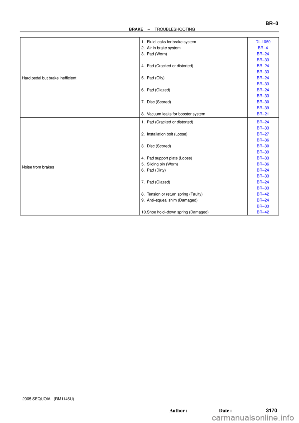
2005 SEQUOIA (RM1146U) Hard pedal but brake inefficient
1. Fluid leaks for brake system
2. Air in brake system
3. Pad (Worn)
4. Pad (Cracked or distorted)
5. Pad (Oily)
6. Pad (Glazed)
7. Disc (Scored)
8. Vacuum leaks for booster systemDI±1059
BR±4
BR±24
BR±33
BR±24
BR±33
BR±24
BR±33
BR±24
BR±33
BR±30
BR±39
BR±21
Noise from brakes
1. Pad (Cracked or distorted)
2. Installation bolt (Loose)
3. Disc (Scored)
4. Pad support plate (Loose)
5. Sliding pin (Worn)
6. Pad (Dirty)
7. Pad (Glazed)
8. Tension or return spring (Faulty)
9. Anti±squeal shim (Damaged)
10.Shoe hold±down spring (Damaged)BR±24
BR±33
BR±27
BR±36
BR±30
BR±39
BR±33
BR±36
BR±24
BR±33
BR±24
BR±33
BR±42
BR±24
BR±33
BR±42
Page 3181 of 4323

BRAKE PEDAL
ON±VEHICLE INSPECTION
1. CHECK PEDAL HEIGHT
Pedal hei")
F07754
Pedal Height Push Rod
BR107±04
R00085
Pedal Free Play BR±6
± BRAKEBRAKE PEDAL
3173 Author�: Date�:
2005 SEQUOIA (RM1146U)
BRAKE PEDAL
ON±VEHICLE INSPECTION
1. CHECK PEDAL HEIGHT
Pedal height from dash panel:
151.1 ± 165.1 mm (5.949 ± 6.500 in.)
NOTICE:
Do not adjust the pedal height. Doing so by changing the
push rod length of the brake booster will structurally
change the pedal ratio.
If the pedal height is incorrect, check that there is no damage
in brake pedal, brake pedal lever, brake pedal bracket and dash
panel.
�Even if there is damage, there is no problem if the
reserve distance is within the standard value.
�If necessary, replace them.
2. IF NECESSARY, ADJUST STOP LIGHT SWITCH
(a) Remove the front door scuff plate, cowl side trim, side
panel, lower finish panel and No. 2 heater to register duct
(See page BO±89).
(b) Loosen the stop light switch lock nut.
(c) Push the brake pedal in 5 ± 15 mm (0.20 ± 0.59 in.), turn
the stop light switch to lock the nut in the position where
the stop light goes off.
(d) Push the brake pedal in 5 ±15 mm (0.20 ± 0.59 in.), check
that the stop light lights up.
(e) Install the No. 2 heater to register duct, lower finish panel,
side panel, cowl side trim and front door scuff plate (See
page BO±89).
3. CHECK PEDAL FREE PLAY
(a) Stop the engine and depress the brake pedal several
times until there is no more vacuum left in the booster.
(b) Push in the pedal by hand until the second point of resis-
tance begins to be felt, then measure the distance as
shown in the illustration.
Pedal free play: 1 ± 6 mm (0.04 ± 0.24 in.)
HINT:
The free play to the first point of resistance is due to the play
between the clevis and pin. It is 1 ± 3 mm (0.04 ± 0.12 in.) at the
pedal.
If incorrect, check the stop light switch clearance. If the clear-
ance is OK, then troubleshoot the brake system.
Stop light switch clearance:
0.5 ± 2.4 mm (0.020 ± 0.095 in.)