Page 3005 of 4323

TROUBLESHOOTING
PROBLEM SYMPTOMS TABLE
Use the table below to help you find the cause of the problem")
SA140±10
± SUSPENSION AND AXLETROUBLESHOOTING
SA±1
2997 Author�: Date�:
2005 SEQUOIA (RM1146U)
TROUBLESHOOTING
PROBLEM SYMPTOMS TABLE
Use the table below to help you find the cause of the problem. The numbers indicate the priority of the likely
cause of the problem. Check each part in order. If necessary, replace these parts.
SymptomSuspect AreaSee page
Bottoming
1. Vehicle (Overloaded)
2. Spring (Weak)
3. Shock absorber (Worn)±
SA±63
SA±135
SA±66
SA±135
Sways/pitches
1. Tire (Worn or improperly inflated)
2. Stabilizer bar (Bent or broken)
3. Shock absorber (Worn)SA±3
SA±90
SA±149
SA±66
SA±135
Front wheel shimmy
1. Tire (Worn or improperly inflated)
2. Wheel (Out of balance)
3. Shock absorber (Worn)
4. Wheel alignment (Incorrect)
5. Ball joints (Worn)
6. Hub bearing (Loose or worn)
7. Steering linkage (Loose or worn)
8. Steering gear (Out of adjustment or broken)SA±3
SA±3
SA±66
SA±4
SA±83
SA±88
SA±21
±
SR±37
Abnormal tire wear
1. Tire (Improperly inflated)
2. Wheel alignment (Incorrect)
3. Shock absorber (Worn)
4. Suspension parts (Worn)SA±3
SA±4
SA±66
SA±139
±
Noise in front differential
1. Oil level (Low or wrong grade)
2. Excessive backlash between pinion and ring gear
3. Ring, pinion or side gear (Worn or chipped)
4. Pinion shaft bearing (Worn)
5. Side bearing (Worn)
6. Differential bearing (Loose or worn)SA±38
SA±50
SA±50
SA±50
SA±50
SA±50
Oil leak from front differential
1. Oil level (Too high or wrong grade)
2. Front differential rear oil seal (Worn or damaged)
3. Side gear oil seal (Worn or damaged)
4. Companion flange (Loose or damaged)
5. Side gear shaft (Damaged)SA±38
SA±38
SA±50
SA±50
SA±50
Noise in rear axle
1. Oil level (Low or wrong grade)
2. Excessive backlash between pinion and ring gear
3. Ring, pinion or side gear (Worn or chipped)
4. Pinion shaft bearing (Worn)
5. Axle shaft bearing (Worn)
6. Differential bearing (Loose or worn)SA±105
SA±109
SA±109
SA±109
SA±94
SA±109
Oil leak from rear axle1. Oil seal (Worn or damaged)
2. Rear axle housing (Cracked)SA±94
±
Oil leak from rear differential
1. Oil level (Too high or wrong grade)
2. Oil seal (Worn or damaged)
3. Companion flange (Loose or damaged)SA±105
SA±105
SA±109
Page 3009 of 4323

If the vehicle height is not as specified, try to adjust it by pushing
down on or lifting the bod")
Z03382
± SUSPENSION AND AXLEFRONT WHEEL ALIGNMENT
SA±5
3001 Author�: Date�:
2005 SEQUOIA (RM1146U)
If the vehicle height is not as specified, try to adjust it by pushing
down on or lifting the body.
2. INSTALL CAMBER±CASTER±KINGPIN GAUGE OR
POSITION VEHICLE ON WHEEL ALIGNMENT TES-
TER
Follow the specific instructions of the equipment manufacturer.
3. INSPECT CAMBER, CASTER AND STEERING AXIS
INCLINATION
Camber, caster and steering axis inclination:
� Camber
UCK35L±GKBSKA
Right±left error
UCK35L±GKBLKA
Right±left error
UCK45L±GKBSKA
Right±left error
UCK45L±GKBLKA
Right±left error
0°08' ± 45' (0.14° ± 0.75°)
30' (0.5°) or less
0°06' ± 45' (0.10° ± 0.75°)
30' (0.5°) or less
0°17' ± 45' (0.28° ± 0.75°)
30' (0.5°) or less
0°16' ± 45' (0.26° ± 0.75°)
30' (0.5°) or less
� Caster (Except air suspension models)
UCK35L±GKBSKA
Tire size: P245/70R16
Tire size: P265/70R16 and P265/65R17
Right±left error
UCK35L±GKBLKA
Right±left error
UCK45L±GKBSKA
Right±left error
UCK45L±GKBLKA
Right±left error
2°56' ± 45' (2.93° ± 0.75°)
2°59' ± 45' (2.98° ± 0.75°)
30' (0.5°) or less
3°02' ± 45' (3.04° ± 0.75°)
30' (0.5°) or less
2°36' ± 45' (2.60° ± 0.75°)
30' (0.5°) or less
2°38' ± 45' (2.64° ± 0.75°)
30' (0.5°) or less
Page 3020 of 4323

F19825
Print Surface
SA±16
± SUSPENSION AND AXLETIRE PRESSURE MONITOR VALVE
3012 Author�: Date�:
2005 SEQUOIA (RM1146U)
REPLACEMENT
1. REM")
SA2CT±01
F19824
Shoe Tire
10 to 20 mm
(0.39 to 0.79 in.)
F19825
Print Surface
SA±16
± SUSPENSION AND AXLETIRE PRESSURE MONITOR VALVE
3012 Author�: Date�:
2005 SEQUOIA (RM1146U)
REPLACEMENT
1. REMOVE FRONT TIRE
2. REMOVE REAR TIRE
3. REMOVE TIRE PRESSURE MONITOR VALVE
(a) Remove the valve core and cap, and release air from the
tire.
(b) After ensuring that air is sufficiently released, remove the
nut and washer that are used to fix the tire pressure moni-
tor valve sub±assy and drop the sensor inside the tire.
HINT:
Keep the removed cap, valve core, nut and washer.
(c) After dropping the tire pressure monitor valve sub±assy
into the tire, disengage the bead using the shoe of the tire
remover.
NOTICE:
Be careful not to damage the tire pressure monitor valve
because of interference between the sensor and tire bead.
(d) Remove the bead on the upper side.
(e) Take out the sensor from the tire and remove the bead on
the lower side.
(f) Remove the inner grommet from the tire pressure monitor
valve sub±assy.
HINT:
Check that there are no cracks or damage to the grommet. If
any damage is found, replace the grommet together with the
washer and nut.
4. INSTALL TIRE PRESSURE MONITOR VALVE
(a) Insert the tire pressure monitor valve into the valve instal-
lation hole. Insert from the inside of the rim so that the print
surface can be seen.
NOTICE:
�Check that there is no visible deformation, damage or
other abnormalities on the transmitter.
�Check that there is no foreign matter on the inner
grommet and around the rim hole.
Page 3025 of 4323
SA143±10
F14316
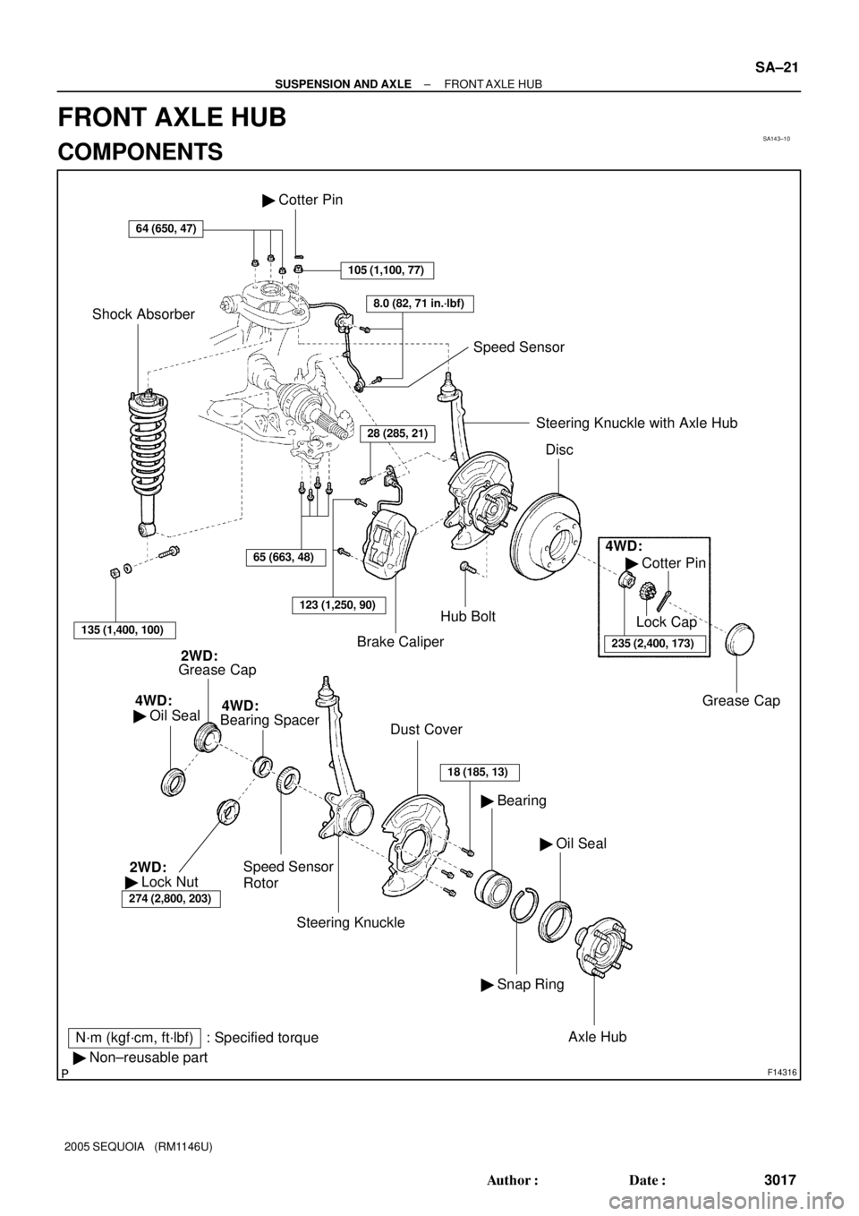
N´m (kgf´cm, ft´lbf) : Specified torque
� Non±reusable part
64 (650, 47)
Brake CaliperHub Bolt � Cotter Pin
105 (1,100, 77)
8.0 (82, 71 in.´lbf)
Speed Sensor
Shock Absorber
135 (1,400, 100)
65 (663, 48)
123 (1,250, 90)
28 (285, 21)Steering Knuckle with Axle Hub
Disc
4WD:
� Cotter Pin
235 (2,400, 173)
Lock Cap
Grease Cap
Grease Cap2WD:
4WD:
� Oil Seal
Speed Sensor
Rotor
Dust Cover
Steering Knuckle
18 (185, 13)
� Oil Seal � Bearing
� Snap Ring
Axle Hub
Bearing Spacer4WD:
274 (2,800, 203)
� Lock Nut 2WD:
± SUSPENSION AND AXLEFRONT AXLE HUB
SA±21
3017 Author�: Date�:
2005 SEQUOIA (RM1146U)
FRONT AXLE HUB
COMPONENTS
Page 3026 of 4323
SA23I±04
R13426
F07263
F07264
F07265
SA±22
± SUSPENSION AND AXLEFRONT AXLE HUB
3018 Author�: Date�:
2005 SEQUOIA (RM1146U)
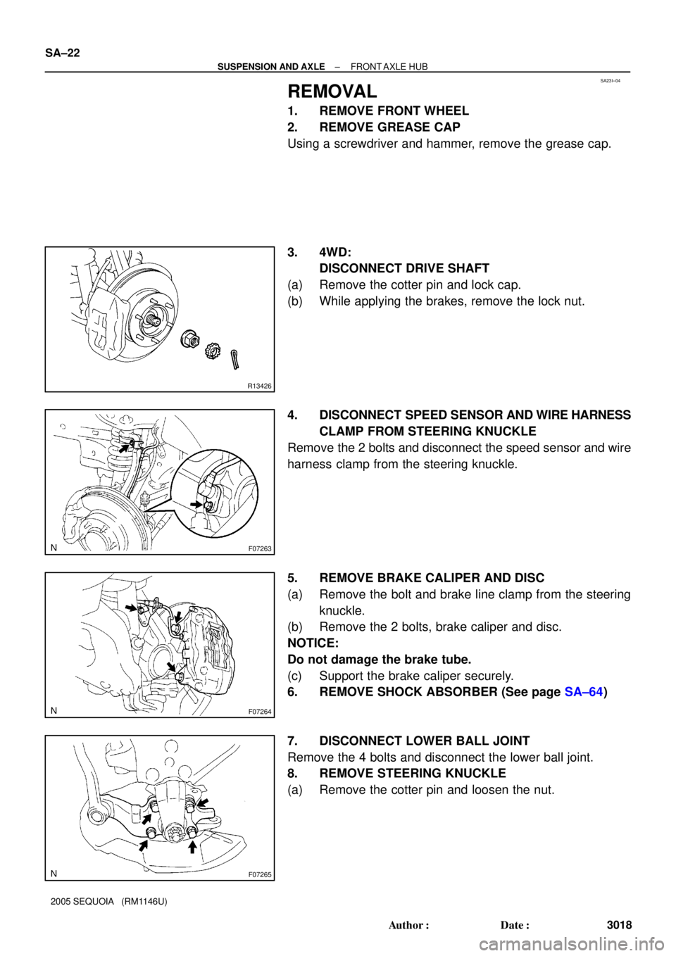
REMOVAL
1. REMOVE FRONT WHEEL
2. REMOVE GREASE CAP
Using a screwdriver and hammer, remove the grease cap.
3. 4WD:
DISCONNECT DRIVE SHAFT
(a) Remove the cotter pin and lock cap.
(b) While applying the brakes, remove the lock nut.
4. DISCONNECT SPEED SENSOR AND WIRE HARNESS
CLAMP FROM STEERING KNUCKLE
Remove the 2 bolts and disconnect the speed sensor and wire
harness clamp from the steering knuckle.
5. REMOVE BRAKE CALIPER AND DISC
(a) Remove the bolt and brake line clamp from the steering
knuckle.
(b) Remove the 2 bolts, brake caliper and disc.
NOTICE:
Do not damage the brake tube.
(c) Support the brake caliper securely.
6. REMOVE SHOCK ABSORBER (See page SA±64)
7. DISCONNECT LOWER BALL JOINT
Remove the 4 bolts and disconnect the lower ball joint.
8. REMOVE STEERING KNUCKLE
(a) Remove the cotter pin and loosen the nut.
Page 3032 of 4323

INSTALLATION
1. INSTALL STEERING KNUCKLE
(a) 4WD:
Insert the drive shaft into the axle hub and temp")
SA23J±05
SA±28
± SUSPENSION AND AXLEFRONT AXLE HUB
3024 Author�: Date�:
2005 SEQUOIA (RM1146U)
INSTALLATION
1. INSTALL STEERING KNUCKLE
(a) 4WD:
Insert the drive shaft into the axle hub and temporarily tighten the nut.
NOTICE:
Be careful not to damage the oil seal and drive shaft boot.
(b) Connect the steering knuckle to the upper suspension arm.
(c) Install the nut and a new cotter pin.
If the holes for the cotter pin are not aligned, tighten the nut further up to 60°.
Torque: 105 N´m (1,100 kgf´cm, 77 ft´lbf)
2. CONNECT LOWER BALL JOINT
Connect the lower ball joint to the steering knuckle with the 4 bolts.
Torque: 65 N´m (663 kgf´cm, 48 ft´lbf)
3. INSTALL SHOCK ABSORBER (See page SA±70)
4. INSTALL BRAKE CALIPER
(a) Install the disc, brake caliper and 2 bolts.
Torque: 123 N´m (1,250 kgf´cm, 90 ft´lbf)
(b) Install the brake line clamp to the steering knuckle with the bolt.
Torque: 28 N´m (285 kgf´cm, 21 ft´lbf)
5. CONNECT SPEED SENSOR AND WIRE HARNESS CLAMP
Connect the speed sensor and wire harness clamp to the steering knuckle with the 2 bolts.
Torque: 8.0 N´m (82 kgf´cm, 71 ft´lbf)
6. 4WD:
INSTALL DRIVE SHAFT LOCK NUT
(a) While applying the brakes, tighten the nut.
Torque: 235 N´m (2,400 kgf´cm, 173 ft´lbf)
(b) Install the lock cap and a new cotter pin.
If the holes for the cotter pin are not aligned, tighten the nut further up to 60°.
7. INSTALL GREASE CAP
8. INSTALL FRONT WHEEL
Torque: 110 N´m (1,150 kgf´cm, 83 ft´lbf)
9. DEPRESS BRAKE PEDAL SEVERAL TIMES
10. CHECK FRONT WHEEL ALIGNMENT (See page SA±4)
11. CHECK SPEED SENSOR SIGNAL (See page DI±899)
12. PERFORM ZERO POINT CALIBRATION OF STEERING ANGLE, MASTER CYLINDER PRES-
SURE, YAW RATE AND DECELERATION SENSORS (See page DI±897)
Page 3034 of 4323
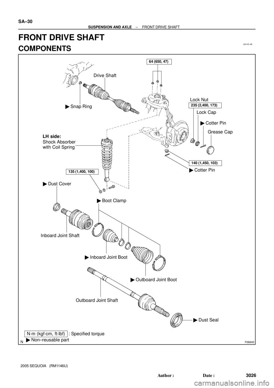
SA14E±08
F06645
� Snap Ring
Drive Shaft
� Dust Cover
Inboard Joint Shaft
� Inboard Joint Boot
� Outboard Joint Boot
� Boot Clamp
� Dust Seal Outboard Joint Shaft
� Cotter Pin� Cotter Pin
Grease Cap Lock Cap Lock Nut
235 (2,400, 173)
140 (1,450, 103)
� Non±reusable part
N´m (kgf´cm, ft´lbf) : Specified torqueShock Absorber
with Coil Spring
135 (1,400, 100)
LH side:
64 (650, 47)
SA±30
± SUSPENSION AND AXLEFRONT DRIVE SHAFT
3026 Author�: Date�:
2005 SEQUOIA (RM1146U)
FRONT DRIVE SHAFT
COMPONENTS
Page 3035 of 4323
SA24L±03
F06624
R12863
SST
R13233
± SUSPENSION AND AXLEFRONT DRIVE SHAFT
SA±31
3027 Author�: Date�:
2005 SEQUOIA (RM1146U)
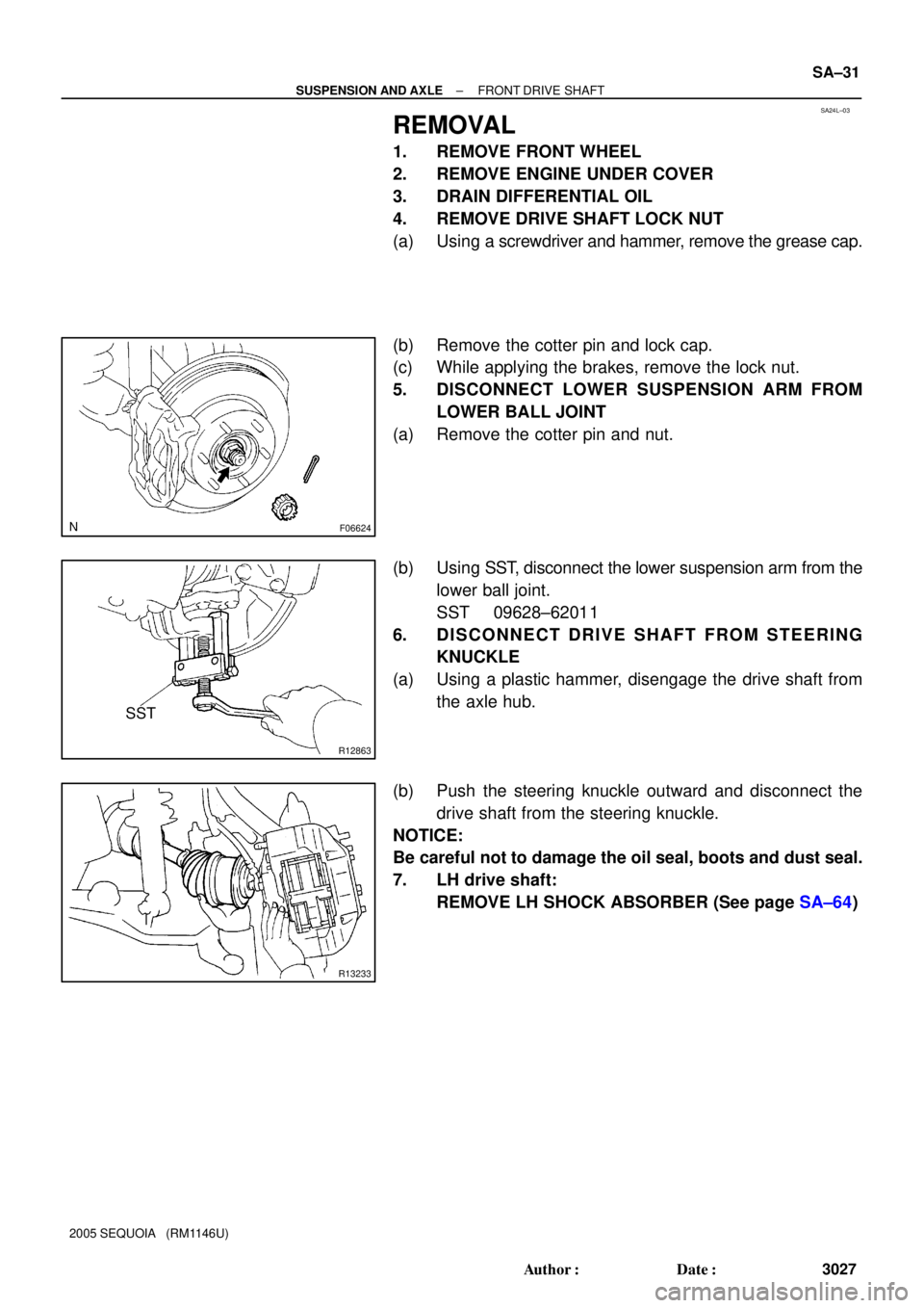
REMOVAL
1. REMOVE FRONT WHEEL
2. REMOVE ENGINE UNDER COVER
3. DRAIN DIFFERENTIAL OIL
4. REMOVE DRIVE SHAFT LOCK NUT
(a) Using a screwdriver and hammer, remove the grease cap.
(b) Remove the cotter pin and lock cap.
(c) While applying the brakes, remove the lock nut.
5. DISCONNECT LOWER SUSPENSION ARM FROM
LOWER BALL JOINT
(a) Remove the cotter pin and nut.
(b) Using SST, disconnect the lower suspension arm from the
lower ball joint.
SST 09628±62011
6. DISCONNECT DRIVE SHAFT FROM STEERING
KNUCKLE
(a) Using a plastic hammer, disengage the drive shaft from
the axle hub.
(b) Push the steering knuckle outward and disconnect the
drive shaft from the steering knuckle.
NOTICE:
Be careful not to damage the oil seal, boots and dust seal.
7. LH drive shaft:
REMOVE LH SHOCK ABSORBER (See page SA±64)