Page 170 of 4323

TORQUE SPECIFICATION
Part tightenedN´mkgf´cmft´lbf
Transfer x Transfer adaptor2424518
Engine rear mou")
SS0PY±05
SS±28
± SERVICE SPECIFICATIONSTRANSFER
170 Author�: Date�:
2005 SEQUOIA (RM1146U)
TORQUE SPECIFICATION
Part tightenedN´mkgf´cmft´lbf
Transfer x Transfer adaptor2424518
Engine rear mounting x Transmission6566048
Crossmember x Frame7273053
Engine rear mounting x Crossmember1818513
Heat insulator x Crossmember1616412
Front suspension member bracket x Crossmember3333624
Filler plug x Transfer3737727
Rear propeller shaft x Rear differential8889765
Rear propeller shaft x Transfer8889765
Protector x Transfer1818513
Front propeller shaft x Front differential7475054
Front propeller shaft x Transfer8889765
Front exhaust pipe x Exhaust manifold6263046
Front exhaust pipe x Center exhaust pipe4849035
Transfer case cover x Transfer front case1818413
Case plug x Transfer front case18.619014
Front bearing retainer x Transfer front case11.511 98
Front output shaft companion flange lock nut11 81,20387
Oil pump x Front case7.56966 in.´lbf
Oil separator x Front case7.56966 in.´lbf
Transfer shift actuator x Transfer case rear2020415
Front case x Transfer case rear2828621
Shift shaft stopper1919414
Drain and filler plug3737727
Transfer extension housing x Transfer case rear121229
Rear output shaft companion flange lock nut11 81,20387
Gear shift fork2424518
Page 172 of 4323
SS07Z±05
SS±30
± SERVICE SPECIFICATIONSPROPELLER SHAFT
172 Author�: Date�:
2005 SEQUOIA (RM1146U)
TORQUE SPECIFICATION
Part tightenedN´mkgf´cmft´lbf
Propeller shaft assembly (2WD)
Propeller shaft x Differential
8889765
Propeller shaft assembly (4WD)
Front propeller shaft x Front differential
Front propeller shaft x Transfer
Rear propeller shaft x Rear differential
Rear propeller shaft x Transfer
74
88
88
88750
897
897
89754
65
65
65
Page 185 of 4323

TORQUE SPECIFICATION
Part tightenedN´mkgf´cmft´lbf
Bleeder plug1111 08
Master cylinder x Reservoir1.5151")
SS085±04
± SERVICE SPECIFICATIONSBRAKE
SS±43
185 Author�: Date�:
2005 SEQUOIA (RM1146U)
TORQUE SPECIFICATION
Part tightenedN´mkgf´cmft´lbf
Bleeder plug1111 08
Master cylinder x Reservoir1.51513 in.´lbf
Master cylinder x Brake booster2525018
Master cylinder x Master cylinder pressure sensor2525018
Brake booster clevis lock nut2525018
Brake booster x Brake booster bracket2525018
Brake booster x Pedal bracket131309
Brake pedal x Pedal bracket3435025
Stop light switch lock nut2526019
Parking brake pedal assembly x Pedal bracket3232023
Parking brake pedal assembly x Body131309
Brake line union nut 10 mm1515511
12 mm19.519514
Front disc brake caliper x Steering knuckle1231,25090
Rear disc brake caliper installation bolt8890065
Rear disc brake caliper x Flexible hose3132023
Rear disc brake torque plate x Backing plate1051,07077
Actuator bracket x Body1111 28
Actuator bracket x Actuator assembly9.59784 in.´lbf
Actuator x Skid control ECU1.81816 in.´lbf
Speed sensor installation bolt8.08271 in.´lbf
Front speed sensor harness x Steering knuckle8.08271 in.´lbf
Front speed sensor harness x Upper arm8.08271 in.´lbf
Front speed sensor harness x Coil support8.08271 in.´lbf
Page 897 of 4323
DIDCB±01
± DIAGNOSTICSAIR SUSPENSION SYSTEM
DI±695
889 Author�: Date�:
2005 SEQUOIA (RM1146U)
AIR SUSPENSION SYSTEM
PRECAUTION
Be sure to switch the height control mode select switch to manual mode and cancel the auto leveling
function when:
�Jacking up the vehicle.
�A trailer etc. is attached to the vehicle.
NOTICE:
When disconnecting the battery terminal, initialize the following system after the terminal is recon-
nected.
System NameSee Page
Back Door Power Window Control SystemBE±77
Page 1091 of 4323
D13491
TC
D6DLC3:
F19136
T17
TC
Tire Pressure Monitor ECU:
D13491CGD6
DLC3:
± DIAGNOSTICSTIRE PRESSURE WARNING SYSTEM
DI±889
1083 Author�: Date�:
2005 SEQUOIA (RM1146U)
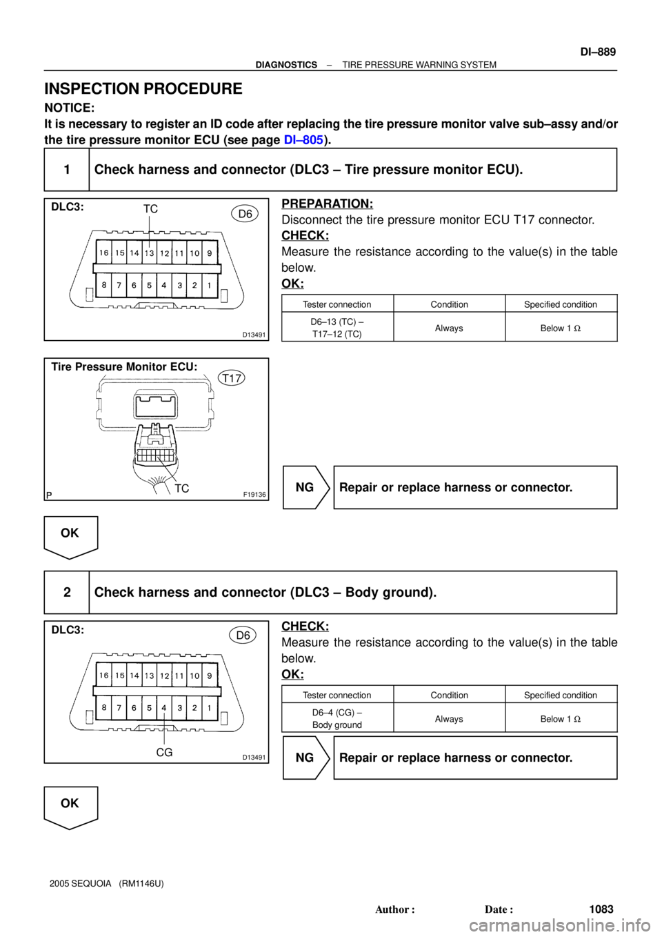
INSPECTION PROCEDURE
NOTICE:
It is necessary to register an ID code after replacing the tire pressure monitor valve sub±assy and/or
the tire pressure monitor ECU (see page DI±805).
1 Check harness and connector (DLC3 ± Tire pressure monitor ECU).
PREPARATION:
Disconnect the tire pressure monitor ECU T17 connector.
CHECK:
Measure the resistance according to the value(s) in the table
below.
OK:
Tester connectionConditionSpecified condition
D6±13 (TC) ±
T17±12 (TC)AlwaysBelow 1 W
NG Repair or replace harness or connector.
OK
2 Check harness and connector (DLC3 ± Body ground).
CHECK:
Measure the resistance according to the value(s) in the table
below.
OK:
Tester connectionConditionSpecified condition
D6±4 (CG) ±
Body groundAlwaysBelow 1 W
NG Repair or replace harness or connector.
OK
Page 1897 of 4323
MIRR POS SW L
Remote control mirror switch L
position/ON or OFF
ON: Remote control mirror switch
L position is s")
± DIAGNOSTICSBODY CONTROL SYSTEM
DI±1695
1889 Author�: Date�:
2005 SEQUOIA (RM1146U)MIRR POS SW L
Remote control mirror switch L
position/ON or OFF
ON: Remote control mirror switch
L position is selected
OFF: Remote control mirror switch
L position is not selected
±
MIRR POS SW UPRemote control mirror switch UP
position/ON or OFF
ON: Remote control mirror switch
UP position is selected
OFF: Remote control mirror switch
UP position is not selected
±
MIRR POS SW DWNRemote control mirror switch
DOWN position/ON or OFF
ON: Remote control mirror switch
DOWN position is selected
OFF: Remote control mirror switch
DOWN position is not selected
±
AUTO LIGHT SWLight control switch (AUTO)/ON or
OFF
ON: Light control switch position is
AUTO
OFF: Light control switch position
is not AUTO
±
HEAD LIGHT SWLight control switch (HEAD)/ON or
OFF
ON: Light control switch position is
HEAD
OFF: Light control switch position
is not HEAD
±
TAIL LIGHT SWLight control switch (TAIL)/ON or
OFF
ON: Light control switch position is
TAIL
OFF: Light control switch position
is not TAIL
±
ILLUMINATE RATEIllumination rate information/
MIN: 0 MAX: 99.99Condition value will be displayed
Normal value: 0.8 ms to 22.0 ms±
SEAT M1 SWMemory seat switch (M1)/ON or
OFF
ON: Memory seat switch position
is M1
OFF: Memory seat switch position
is not M1
±
SEAT M2 SWMemory seat switch (M2)/ON or
OFF
ON: Memory seat switch position
is M2
OFF: Memory seat switch position
is not M2
±
SEAT SET SWMemory seat switch (SET)/ON or
OFF
ON: Memory seat switch position
is SET
OFF: Memory seat switch position
is not SET
±
GLS BRK DETECTGlass breakage sensor/ON or
OFF
ON: Glass breakage sensor oper-
ates
OFF: Glass breakage sensor does
not operate
±
WIRELESS OPERWireless door lock control func-
tion/ON or OFF
ON: Wireless door lock function
operated
OFF: Wireless door lock function
not operated
±
OPEN DOOR WARNDOOR indicator light/ON or OFFON: Any door is open
OFF: All doors are closed±
AUTO LOCK DELAYAuto lock delay/60s or 30sCustomized value will be dis-
played±
UNLOCK/2OPER2 time operation wireless unlock
signal/ON or OFFCustomized condition will be dis-
played±
Page 2091 of 4323
DIDFN±01
B78765I28978
Battery
Serial Communication Switch
ECUOn On
Off
ECULight
Motor
Heater
Solenoid � Conceptual Drawing �
I28977
Frame
Data
Header End Message
± DIAGNOSTICSMULTIPLEX COMMUNICATION SYSTEM
DI±1889
2083 Author�: Date�:
2005 SEQUOIA (RM1146U)
SYSTEM DESCRIPTION
Basic of MPX (Multiplex Communication)
1. General
The SEQUOIA multiplex communication system uses serial communication, which converts multiple pieces
of information into serial communication data. As a result, they can be transmitted through a single commu-
nication wire.
Serial communication data consists of bits and frames. A bit is the basic unit that represents the amount of
information. A bit is represented by a binary value º0º or º1º. A frame is a body of data that is transmitted
together. A frame contains a ºheaderº that indicates the beginning of the data and an ºend messageº that
indicates the end of the data.
Page 2650 of 4323

(c) Moun")
A02859
A02889
Service Bolt
SST
Sub Gear
Main Gear
Turn
A23353Front
A23343
5 mm Hexagon
Wrench SST
A03173
± ENGINE MECHANICALCYLINDER HEAD
EM±63
2642 Author�: Date�:
2005 SEQUOIA (RM1146U)
(c) Mount the hexagon wrench head portion of the camshaft
in a vise.
NOTICE:
Be careful not to damage the camshaft.
(d) Using SST, align the holes of the camshaft main gear and
sub±gear by turning the camshaft sub±gear counter-
clockwise, and temporarily install a service bolt.
SST 09960±10010 (09962±01000, 09963±00500)
(e) Align the gear teeth of the main gear and sub±gear, and
tighten the service bolt.
7. INSTALL CAMSHAFT TIMING TUBE TO INTAKE CAM-
SHAFT
(a) Place a new oil seal to the timing tube.
NOTICE:
Be careful of the installation direction.
(b) Align the timing tube knock pin with the knock pin groove
of the drive gear, and temporarily install the drive gear
with the 4 bolts.
(c) Using SST and a 5 mm hexagon wrench, uniformly tight-
en the 4 bolts in several steps.
SST 09960±10010 (09962±01000, 09963±00500)
Torque: 7.5 N´m (76 kgf´cm, 66 in.´lbf)
NOTICE:
Be careful not to damage the timing tube.
(d) Mount the hexagon head portion of the camshaft in a vise.
NOTICE:
Be careful not to damage the camshaft.