Page 5 of 4323
BE1367
Medium Current Fuse and High Current Fuse
Equal Amperage Rating
V00076
Abbreviation Part Name Symbol Illustration
FUSE
MEDIUM CURRENT FUSE
HIGH CURRENT FUSE
FUSIBLE LINK
CIRCUIT BREAKERFUSE
M±FUSE
H±FUSE
FL
CB
± INTRODUCTIONREPAIR INSTRUCTIONS
IN±5
5 Author�: Date�:
2005 SEQUOIA (RM1146U)
(3) Precoated parts are indicated in the component il-
lustrations by the º�º symbol.
(g) When necessary, use a sealer on gaskets to prevent
leaks.
(h) Carefully observe all specifications for bolt tightening
torques. Always use a torque wrench.
(i) Use of special service tools (SST) and special service ma-
terials (SSM) may be required, depending on the nature
of the repair. Be sure to use SST and SSM where speci-
fied and follow the proper work procedure. A list of SST
and SSM can be found in the Preparation section in this
manual.
(j) When replacing fuses, be sure the new fuse has the cor-
rect amperage rating. DO NOT exceed the rating or use
one with a lower rating.
Page 239 of 4323
± DIAGNOSTICSENGINE
DI±45
239 Author�: Date�:
2005 SEQUOIA (RM1146U)
3. CLEAR DTC (Not using the hand±held tester)
(a) Remove the EFI No. 1 and ETCS fuses from the engine
room J/B for more than 60 seconds, or disconnect the bat-
tery terminal for more than 60 seconds.
After disconnecting the battery terminal, perform the ºINI-
TIALIZEº procedure.
Page 1137 of 4323
F16988
GND
+BM
+BS
± DIAGNOSTICSABS WITH EBD & BA & TRAC & VSC SYSTEM
DI±935
1129 Author�: Date�:
2005 SEQUOIA (RM1146U)
INSPECTION PROCEDURE
1 Check voltage between terminals +BS, +BM and GND of the skid control ECU
connector.
PREPARATION:
Disconnect the skid control ECU connector.
CHECK:
Measure the voltage between terminals +BS, +BM and GND of
the skid control ECU harness side connector.
OK:
Voltage: 10 to 14 V
NG Check and replace ABS fuses.
Check and repair harness or connector.
OK
If the same code is still indicated after the DTC is deleted, check the condition of each connection.
If the connections are normal, the skid control ECU may be defective.
NOTICE:
When replacing the skid control ECU, perform the zero point calibration (See page DI±897).
Page 1718 of 4323
DI±1516± DIAGNOSTICSPOWER SEAT CONTROL SYSTEM (w/ Driving Position
Memory)
1710 Author�: Date�:
2005 SEQUOIA (RM1146U)
INSPECTION PROCEDURE
1 Check fuse (PWR SEAT, ECU±IG, AM1).
PREPARATION:
Remove the PWR SEAT, ECU±IG and AM1 fuses from the instrument panel J/B.
CHECK:
Measure the resistance.
OK:
Below 1 W
NG Replace fuse.
OK
Page 1747 of 4323

DIDF0±01
A04550
TC CG
1 2345678
9
10 11 12 1314 15 16
I11929
CRUISE Main
Indicator Light
I28693
Normal System Code:
ON
OFF
Code 52
Code 21 0.25 sec.
0.25 sec.
ON
OFFDiagnostic Trouble Code:
4.5 sec. 2.5 sec. 1.5 sec. 0.5 sec.
0.5 sec.
± DIAGNOSTICSCRUISE CONTROL SYSTEM
DI±1545
1739 Author�: Date�:
2005 SEQUOIA (RM1146U)
DTC CHECK / CLEAR
1. DTC CHECK (USING SST CHECK WIRE)
(a) Using SST check wire, connect terminals TC and CG
of
the DLC3.
SST 09843±18040
(b) Turn the ignition switch to the ON position.
(c) Read and record DTCs from the CRUISE main indicator
light on the combination meter. As examples, refer to the
chart below for the blinking patterns of the normal system
code, and diagnostic trouble codes 21 and 52.
(d) Refer to the Diagnostic Trouble Code Chart (see page
DI±1549) for DTC information.
2. DTC CLEAR (USING SST CHECK WIRE)
Remove the EFI No.1 and ETCS fuses from the engine room
J/B for more than 60 seconds, or disconnect the battery termi-
nal for more than 60 seconds.
Page 1904 of 4323
DI±1702
± DIAGNOSTICSBODY CONTROL SYSTEM
1896 Author�: Date�:
2005 SEQUOIA (RM1146U)
INSPECTION PROCEDURE
1 Check RAD No. 2, AM1, WSH, ECU±IG, Door No. 2 and ECU±B fuses.
CHECK:
Check for continuity of the RAD No. 2, AM1, WSH, ECU±IG, door No. 2 and ECU±B fuses.
OK:
Continuity
NG Replace defective fuse.
OK
2 Check voltage between terminals ACC, WIG, IG, BECU, S+B, BDR and GND1 of
body ECU connector.
PREPARATION:
Turn the ignition switch ON.
CHECK:
Measure the voltage between terminals ACC, WIG, IG and GND1.
OK:
Voltage: 10 to 14 V
PREPARATION:
Turn the ignition switch OFF.
CHECK:
Measure the voltage between terminals BECU, BDR, S+B and GND1.
OK:
Voltage: 10 to 14 V
OK Proceed to next circuit inspection shown in
problem symptoms table (See page DI±1686).
NG
Page 2749 of 4323

D13872
Hand±Held Tester
DLC3
CAN VIM
SF12Y±05
B16497
Up
Pulsation
DamperScrew
B16528
SST
(Gauge)
Front
Fuel
Pipe
Gasket SST
(Union)SST
(Adaptor)
± SFIFUEL PUMP
SF±7
2741 Author�: Date�:
2005 SEQUOIA (RM1146U)
FUEL PUMP
ON±VEHICLE INSPECTION
1. CHECK FUEL PUMP OPERATION
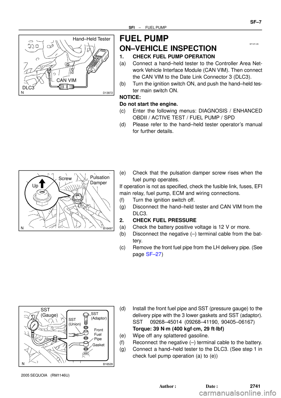
(a) Connect a hand±held tester to the Controller Area Net-
work Vehicle Interface Module (CAN VIM). Then connect
the CAN VIM to the Date Link Connector 3 (DLC3).
(b) Turn the ignition switch ON, and push the hand±held tes-
ter main switch ON.
NOTICE:
Do not start the engine.
(c) Enter the following menus: DIAGNOSIS / ENHANCED
OBDII / ACTIVE TEST / FUEL PUMP / SPD
(d) Please refer to the hand±held tester operator's manual
for further details.
(e) Check that the pulsation damper screw rises when the
fuel pump operates.
If operation is not as specified, check the fusible link, fuses, EFI
main relay, fuel pump, ECM and wiring connections.
(f) Turn the ignition switch off.
(g) Disconnect the hand±held tester and CAN VIM from the
DLC3.
2. CHECK FUEL PRESSURE
(a) Check the battery positive voltage is 12 V or more.
(b) Disconnect the negative (±) terminal cable from the bat-
tery.
(c) Remove the front fuel pipe from the LH delivery pipe. (See
page SF±27)
(d) Install the front fuel pipe and SST (pressure gauge) to the
delivery pipe with the 3 lower gaskets and SST (adaptor).
SST 09268±45014 (09268±41190, 90405±06167)
Torque: 39 N´m (400 kgf´cm, 29 ft´lbf)
(e) Wipe off any splattered gasoline.
(f) Reconnect the negative (±) terminal cable to the battery.
(g) Connect a hand±held tester to the DLC3. (See step 1 in
check fuel pump operation (a) to (e))
Page 2902 of 4323

B07243
Voltmeter
Maintenance±Free Battery
P14937
Maintenance±Free Battery
GREEN EYE DARK EYECLEAR EYE or
CHARGED DISCHARGED ADD WATERLIGHT YELLOW
Z00030
B00807
CH±2
± CHARGINGCHARGING SYSTEM
2894 Author�: Date�:
2005 SEQUOIA (RM1146U)
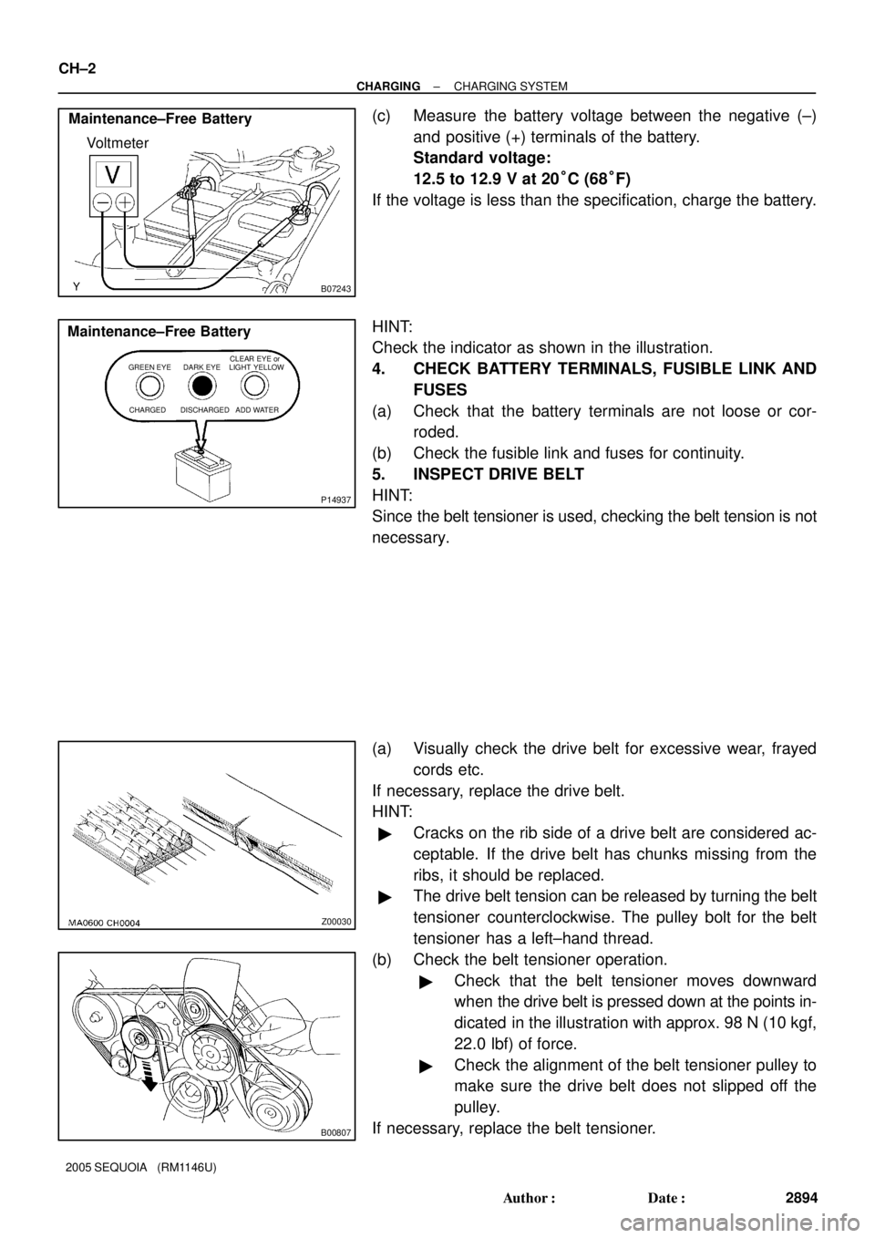
(c) Measure the battery voltage between the negative (±)
and positive (+) terminals of the battery.
Standard voltage:
12.5 to 12.9 V at 20°C (68°F)
If the voltage is less than the specification, charge the battery.
HINT:
Check the indicator as shown in the illustration.
4. CHECK BATTERY TERMINALS, FUSIBLE LINK AND
FUSES
(a) Check that the battery terminals are not loose or cor-
roded.
(b) Check the fusible link and fuses for continuity.
5. INSPECT DRIVE BELT
HINT:
Since the belt tensioner is used, checking the belt tension is not
necessary.
(a) Visually check the drive belt for excessive wear, frayed
cords etc.
If necessary, replace the drive belt.
HINT:
�Cracks on the rib side of a drive belt are considered ac-
ceptable. If the drive belt has chunks missing from the
ribs, it should be replaced.
�The drive belt tension can be released by turning the belt
tensioner counterclockwise. The pulley bolt for the belt
tensioner has a left±hand thread.
(b) Check the belt tensioner operation.
�Check that the belt tensioner moves downward
when the drive belt is pressed down at the points in-
dicated in the illustration with approx. 98 N (10 kgf,
22.0 lbf) of force.
�Check the alignment of the belt tensioner pulley to
make sure the drive belt does not slipped off the
pulley.
If necessary, replace the belt tensioner.