Page 1702 of 4323
H23483CG
DLC3:
D6
H23040TC
A20
DI±1500
± DIAGNOSTICSSUPPLEMENTAL RESTRAINT SYSTEM
1694 Author�: Date�:
2005 SEQUOIA (RM1146U)
2 Check wire harness (CG of DLC3 ± body ground).
CHECK:
Measure the resistance according to the value(s) in the table
below.
OK:
Tester ConnectionConditionSpecified Condition
D6±4 (CG) ± Body groundAlwaysBelow 1 W
NG Repair or replace wire harness (CG of DLC3 to
body ground).
OK
3 Check wire harness (TC of airbag sensor assembly ± body ground).
CHECK:
Measure the resistance according to the value(s) in the table
below.
OK:
Tester ConnectionConditionSpecified Condition
A20±15 (TC) ±
Body groundAlways1 MW or higher
NG Repair or replace wire harness or each ECU.
OK
Replace airbag sensor assembly (see page RS±82).
Page 1816 of 4323

PROBLEM SYMPTOMS TABLE
HINT:
Inspect the related ºFuseº and ºRelayº before confirming the su")
DID8U±01
DI±1614
± DIAGNOSTICSCOMBINATION METER SYSTEM
1808 Author�: Date�:
2005 SEQUOIA (RM1146U)
PROBLEM SYMPTOMS TABLE
HINT:
Inspect the related ºFuseº and ºRelayº before confirming the suspected area as shown in the table below.
MALFUNCTION SYSTEM:
SymptomSuspected AreaSee page
Entire combination meter does not operate.Refer to troubleshooting proceduresDI±1628
Operating light control rheostat does not change light brightness.Refer to troubleshooting proceduresDI±1645
Seat belt warning does not operate.Refer to troubleshooting proceduresDI±1650
Key reminder warning buzzer does not sound.
1. Multiplex communication system
2. Key unlock warning switch circuit
3. Door courtesy lamp switch circuit
4. Combination meter assyDI±1892
DI±1715
DI±1728
IN±35
METER GAUGES:
SymptomSuspected AreaSee page
Malfunction in speedometerRefer to troubleshooting proceduresDI±1632
Malfunction in tachometerRefer to troubleshooting proceduresDI±1636
Malfunction in fuel receiver gaugeRefer to troubleshooting proceduresDI±1640
Malfunction in engine coolant temperature receiver gaugeRefer to troubleshooting proceduresDI±1644
Malfunction in oil pressure receiver gaugeRefer to troubleshooting proceduresDI±1654
Malfunction in volt meterRefer to troubleshooting proceduresDI±1658
WARNING LIGHTS:
SymptomSuspected AreaSee page
Check engine warning light (MIL) does not come on.
1. ECM
2. Wire harness or connector
3. Combination meter assyDI±9
±
IN±35
Discharge warning light does not come on.
1. ECM
2. Wire harness or connector
3. Combination meter assyDI±9
±
IN±35
Brake warning light does not come on.
1. Skid control ECU
2. Wire harness or connector
3. Combination meter assyDI±895
±
IN±35
ABS warning light does not come on.
1. Skid control ECU
2. Wire harness or connector
3. Combination meter assyDI±895
±
IN±35
SRS warning light does not come on.
1. Airbag sensor assy
2. Wire harness or connector
3. Combination meter assyDI±1126
±
IN±35
Open door warning light does not come on.
1. Door courtesy light switch circuit
2. Wire harness or connector
3. Combination meter assy
4. Body ECUDI±1728
±
IN±35
IN±35
Fuel level warning light does not come on.
1. Refer to troubleshooting
2. Wire harness or connector
3. Combination meter assyDI±1640
±
IN±35
Low oil pressure warning light does not come on.
1. Low oil pressure warning switch
2. Wire harness or connector
3. Combination meter assyBE±55
±
IN±35
Page 1826 of 4323

Wire harness side
1
2
3
4
5
6
13
14
15
16
17
18
19
20
21
22
23
24
25
26
27
28
29
30
31
32
33
34
35
36
37
38
39
401
2
3
4
5
8 6
10
11
12
13
14
15
16
17
18
19
21
23
24
Terminal No.
Translate ECU
ECM
STA Fuse
Front Seat Inner Belt LH (Buckle Switch)
Overhead Module (Garage Door Opener)
Overhead Module (Garage Door Opener)
Washer Level Sensor
ECM
ECM (*1)
Transponder Key Computer
Body ECU
ECM
ECM
Tire Pressure Monitor ECU
Injector No. 1
Light Control Rheostat
ECM
Speed Sensor
4P OUT (Other Parts)
Fuel Sender Gauge
Oil Pressure Sender Gauge
IGN Fuse
Airbag Sensor Assembly
Memory Seat ECU and SW (*2)
Back Door ECU
Integration Control and Panel
Turn Signal Flasher Relay
Park/Neutral Position Switch
Airbag Sensor AssemblyTranslate ECU
Translate ECU
Skid Control ECU
4WD Control ECU
Alternator
Speed Sensor
Fuel Sender Gauge
Ground
Suspension Control ECU
Body ECU (*4)
Body ECU (*3)
Turn Signal Flasher Relay
Skid Control ECU
ECU±B Fuse
IGN1 Fuse Connectors:
Terminal No.
Wire harness side
C5
C64WD Control ECU
4WD Control ECU
Suspension Control ECU
Suspension Control ECU
Suspension Control ECU
*1: 4WD
*2: w/ Driving Position Memory
*3: w/ Daytime Running Light
*4: w/o Daytime Running LightPark/Neutral Position Switch
Park/Neutral Position Switch
Park/Neutral Position Switch
Park/Neutral Position Switch
Park/Neutral Position Switch DI±1624
± DIAGNOSTICSCOMBINATION METER SYSTEM
1818 Author�: Date�:
2005 SEQUOIA (RM1146U)
Page 1837 of 4323
I28569
Combination Meter:
C5±24
I28570
Combination Meter:
C6±12
C6±10
I28573
Vehicle Speed Sensor
Wire Harness Side:
V1
± DIAGNOSTICSCOMBINATION METER SYSTEM
DI±1635
1829 Author�: Date�:
2005 SEQUOIA (RM1146U)
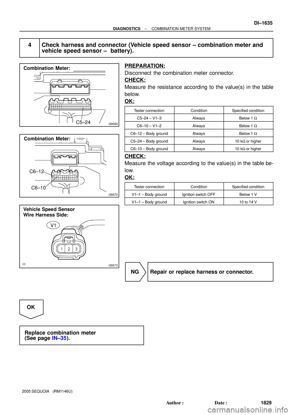
4 Check harness and connector (Vehicle speed sensor ± combination meter and
vehicle speed sensor ± battery).
PREPARATION:
Disconnect the combination meter connector.
CHECK:
Measure the resistance according to the value(s) in the table
below.
OK:
Tester connectionConditionSpecified condition
C5±24 ± V1±3AlwaysBelow 1 W
C6±10 ± V1±2AlwaysBelow 1 W
C6±12 ± Body groundAlwaysBelow 1 W
C5±24 ± Body groundAlways10 kW or higher
C6±10 ± Body groundAlways10 kW or higher
CHECK:
Measure the voltage according to the value(s) in the table be-
low.
OK:
Tester connectionConditionSpecified condition
V1±1 ± Body groundIgnition switch OFFBelow 1 V
V1±1 ± Body groundIgnition switch ON10 to 14 V
NG Repair or replace harness or connector.
OK
Replace combination meter
(See page IN±35).
Page 1956 of 4323

INSPECTION PROCEDURE
1 Check automatic light control sensor.
When using hand±held tester:
PREPARATION:
(a) Con")
DI±1754
± DIAGNOSTICSBODY CONTROL SYSTEM
1948 Author�: Date�:
2005 SEQUOIA (RM1146U)
INSPECTION PROCEDURE
1 Check automatic light control sensor.
When using hand±held tester:
PREPARATION:
(a) Connect the hand±held tester to the DLC3.
(b) Turn the ignition switch and hand±held tester main switch ON.
BODY ECU:
ItemMeasurement Item/Display
(Range)Normal ConditionDiagnostic Note
ILLUMINATE RATEIllumination rate information/
MIN: 0 MAX: 99.99Condition value will be displayed
Normal value: 0.8 ms to 22.0 ms±
CHECK:
The illumination rate value should change within the following range such as when the light sensor is ex-
posed to light or covered by hand.
OK:
0.8 ms to 22.0 ms
HINT:
Time needed for the light sensor to generate one cycle of frequency according to the brightness.
When not using hand±held tester (See page BE±27):
NG Replace automatic light control sensor.
OK
2 Check harness and connector between automatic light control sensor and body
ECU (See page IN±35).
NG Repair or replace wire harness or connector.
OK
Proceed to next inspection shown in problem
symptoms table (See page DI±1686).
Page 1978 of 4323
DI±1776
± DIAGNOSTICSBODY CONTROL SYSTEM
1970 Author�: Date�:
2005 SEQUOIA (RM1146U)
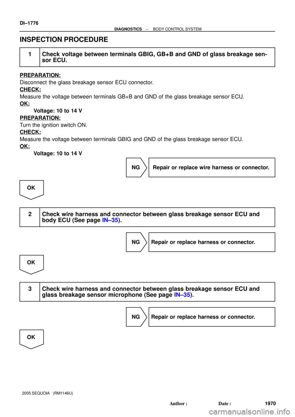
INSPECTION PROCEDURE
1 Check voltage between terminals GBIG, GB+B and GND of glass breakage sen-
sor ECU.
PREPARATION:
Disconnect the glass breakage sensor ECU connector.
CHECK:
Measure the voltage between terminals GB+B and GND of the glass breakage sensor ECU.
OK:
Voltage: 10 to 14 V
PREPARATION:
Turn the ignition switch ON.
CHECK:
Measure the voltage between terminals GBIG and GND of the glass breakage sensor ECU.
OK:
Voltage: 10 to 14 V
NG Repair or replace wire harness or connector.
OK
2 Check wire harness and connector between glass breakage sensor ECU and
body ECU (See page IN±35).
NG Repair or replace harness or connector.
OK
3 Check wire harness and connector between glass breakage sensor ECU and
glass breakage sensor microphone (See page IN±35).
NG Repair or replace harness or connector.
OK
Page 2006 of 4323
DI±1804
± DIAGNOSTICSDRIVER DOOR CONTROL SYSTEM
1998 Author�: Date�:
2005 SEQUOIA (RM1146U)
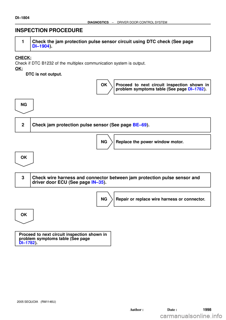
INSPECTION PROCEDURE
1 Check the jam protection pulse sensor circuit using DTC check (See page
DI±1904).
CHECK:
Check if DTC B1232 of the multiplex communication system is output.
OK:
DTC is not output.
OK Proceed to next circuit inspection shown in
problem symptoms table (See page DI±1782).
NG
2 Check jam protection pulse sensor (See page BE±69).
NG Replace the power window motor.
OK
3 Check wire harness and connector between jam protection pulse sensor and
driver door ECU (See page IN±35).
NG Repair or replace wire harness or connector.
OK
Proceed to next circuit inspection shown in
problem symptoms table (See page
DI±1782).
Page 2014 of 4323
DI±1812
± DIAGNOSTICSDRIVER DOOR CONTROL SYSTEM
2006 Author�: Date�:
2005 SEQUOIA (RM1146U)
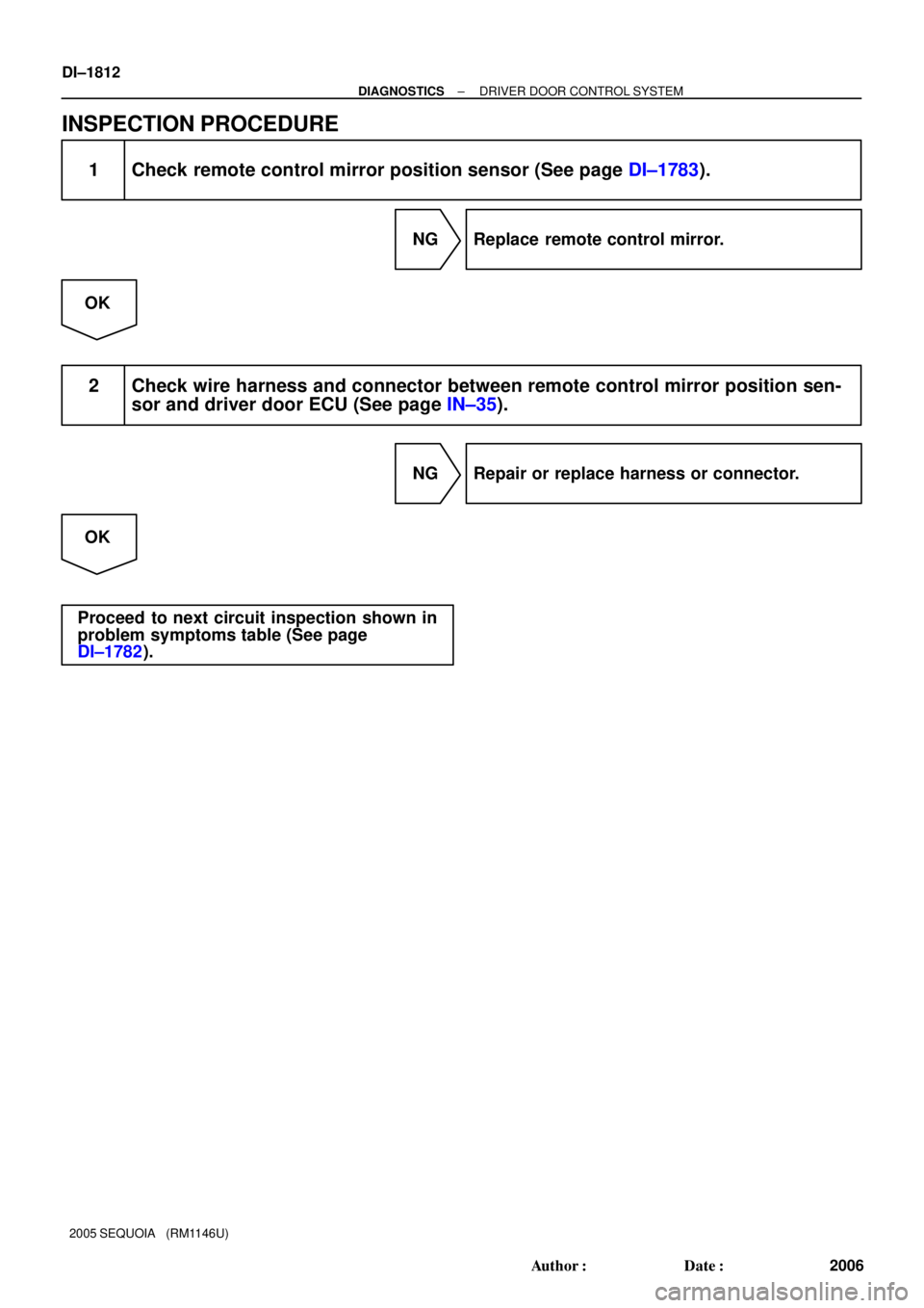
INSPECTION PROCEDURE
1 Check remote control mirror position sensor (See page DI±1783).
NG Replace remote control mirror.
OK
2 Check wire harness and connector between remote control mirror position sen-
sor and driver door ECU (See page IN±35).
NG Repair or replace harness or connector.
OK
Proceed to next circuit inspection shown in
problem symptoms table (See page
DI±1782).