Page 388 of 4323
A19885
0.8 mm
(0.031 in.)
DI±194
± DIAGNOSTICSENGINE
388 Author�: Date�:
2005 SEQUOIA (RM1146U)
5 Check spark plug and spark of misfiring cylinder.
PREPARATION:
(a) Remove the ignition coil assembly.
(b) Remove the spark plug.
CHECK:
(a) Check the electrode for carbon deposits.
(b) Check the spark plug type (See page IG±1).
(c) Check electrode gap.
OK:
No large carbon deposit present.
Not wet with gasoline or oil.
Electrode gap: 0.8 mm (0.031 in.)
NOTICE:
If adjusting the gap of a new spark plug, bend only ºthe
base / groundº electrode. Do not touch the tip. Never at-
tempt to adjust the gap of a used plug.
PREPARATION:
(a) Install the spark plug to the ignition coil assembly.
(b) Disconnect the injector connector.
(c) Ground spark plug.
CHECK:
Check if spark occurs while engine is being cracked.
CAUTION:
Always disconnect each injector connector.
NOTICE:
Do not crank the engine for more than 2 seconds.
OK:
Spark occurs across electrode gap.
OK Go to step 8.
NG
Page 1792 of 4323
DI±1590
± DIAGNOSTICSENGINE IMMOBILISER SYSTEM
1784 Author�: Date�:
2005 SEQUOIA (RM1146U)
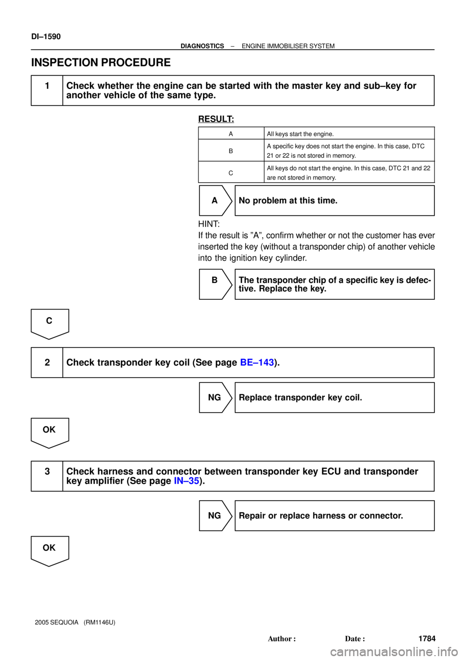
INSPECTION PROCEDURE
1 Check whether the engine can be started with the master key and sub±key for
another vehicle of the same type.
RESULT:
AAll keys start the engine.
BA specific key does not start the engine. In this case, DTC
21 or 22 is not stored in memory.
CAll keys do not start the engine. In this case, DTC 21 and 22
are not stored in memory.
A No problem at this time.
HINT:
If the result is ºAº, confirm whether or not the customer has ever
inserted the key (without a transponder chip) of another vehicle
into the ignition key cylinder.
B The transponder chip of a specific key is defec-
tive. Replace the key.
C
2 Check transponder key coil (See page BE±143).
NG Replace transponder key coil.
OK
3 Check harness and connector between transponder key ECU and transponder
key amplifier (See page IN±35).
NG Repair or replace harness or connector.
OK
Page 2745 of 4323

B16499
Fulcrum
Length
30 cm
SST
B02714
CORRECT
WRONG
Delivery Pipe O±Ring
B04939
Delivery
Pipe
Intake
Manifold O±Ring
Grommet
Injector
Insulator
B17532
Quick Type
Disconnect
B11684
Quick Type
Push
Pull
± SFISFI SYSTEM
SF±3
2737 Author�: Date�:
2005 SEQUOIA (RM1146U)
(3) Using SST, tighten the union bolt to the specified
torque.
SST 09612±24014 (09617±24011)
Torque:
33 N´m (340 kgf´cm, 24 ft´lbf) for use with SST
39 N´m (400 kgf´cm, 29 ft´lbf)
HINT:
Use a torque wrench with a fulcrum length of 30 cm (11.81 in.).
(c) Observe the following precautions when removing or
installing the injectors.
(1) Never reuse the O±ring.
(2) When placing a new O±ring on the injector, take
care not to damage it in any way.
(3) Coat a new O±ring with spindle oil or gasoline be-
fore installing. Never use engine, gear or brake oil.
(d) Install the injector to the delivery pipe and intake manifold
as shown in the illustration.
Before installing the injector, apply spindle oil or gasoline
on the place where the delivery pipe or the intake man-
ifold touches the O±ring of the injector.
(e) Observe the following when disconnecting the fuel tube
connector (quick type):
(1) Check if there is any dirt in the pipe and around the
connector before disconnecting the fuel tube con-
nector. If necessary, clean the dirt away.
(2) Disconnect the fuel pipe clamp from the connector.
(3) Be sure to disconnect them by hand.
(4) When the connector and the pipe are stuck, push
and pull the connector. Then disconnect and pull it
out. Do not use any tools at this time.
(5) Check if there is any dirt or other foreign matter on
the seal surface of the disconnected pipe. If neces-
sary, clean the dirt away.
(6) Do not damage the disconnected pipe and connec-
tor and prevent intrusion of foreign objects by cover-
ing them with a plastic bag.
Page 2746 of 4323

B11683
Quick Type
Push
B12520
Quick Type
Pull
B17533
Quick Type
Install
B06584
Metallic Type
O±Ring Retainer Pipe
Nylon Tube
Housing
B09688
Metallic Type
SST
SF±4
± SFISFI SYSTEM
2738 Author�: Date�:
2005 SEQUOIA (RM1146U)
(f) Observe the following when connecting the fuel tube con-
nector (quick type):
(1) Check if there is any damage or foreign objects in
the connected part of the pipe.
(2) Match the axis of the connector with the axis of the
pipe, and push into the connector until a ºclickº
sound is heard. If the connection is tight, apply a
small amount of fresh engine oil on the tip of the
pipe.
(3) After finishing the connection, pull the pipe and the
connector to ensure it is secure.
(4) Check to make sure no fuel leak is present.
If the result is not specified, repair or replace.
(5) Install the fuel pipe clamp to the connector.
(6) Check to make sure no fuel leak is present.
If the result is not specified, repair or replace.
(g) Observe the following when disconnecting the fuel tube
connector (metallic type):
HINT:
The structure of the metallic connector is shown on the left.
(1) Check if there is any dirt in the pipe and around the
connector before disconnecting the fuel tube con-
nector. If necessary, clean the dirt away.
(2) Assemble SST to the connecting part, as shown in
the illustration.
SST 09268±21010
Page 2747 of 4323

B10036
Metallic Type
Pull Connector
B10485
Metallic Type
Push
B10485
Metallic Type
Pull
± SFISFI SYSTEM
SF±5
2739 Author�: Date�:
2005 SEQUOIA")
B10035
Metallic Type
SST
Insert Retainer
(at 4 places)
B10036
Metallic Type
Pull Connector
B10485
Metallic Type
Push
B10485
Metallic Type
Pull
± SFISFI SYSTEM
SF±5
2739 Author�: Date�:
2005 SEQUOIA (RM1146U)
(3) Turn the SST, align the retainers inside the connec-
tor with the SST chamfered parts and insert the SST
into the connector.
(4) While holding the SST, pull the connector towards
the SST to put the retainers on the SST chamfered
parts.
(5) Slide the SST and connector together towards the
fuel tube assembly.
(h) Observe the following when connecting the fuel tube con-
nector (metallic type):
(1) Check if there is any damage or foreign objects in
the connected part of the pipe.
(2) Match the axis of the connector with the axis of the
pipe, and push into the connector until a ºclickº
sound is heard. If the connection is tight, apply a
small amount of fresh engine oil on the tip of the
pipe.
(3) After finishing the connection, pull the pipe and the
connector to ensure it is secure.
(4) Check to make sure no fuel leak is present.
If the result is not specified, repair or replace.
(i) Observer the following when handling the nylon tube:
(1) Pay attention not to turn the connected part of the
nylon tube and the quick connector with tube when
connecting them.
(2) Pay attention not to kink the nylon tube.
(3) Do not remove the nylon tube.
(4) Do not close the piping with the nylon tube by bend-
ing it.
Page 2924 of 4323
D13866
AT±8
± AUTOMATIC TRANSMISSION (A750E, A750F)ATF TEMPERATURE SENSOR
2916 Author�: Date�:
2005 SEQUOIA (RM1146U)
7. INSTALL OIL PAN
HINT:
Remove any packing material, and be careful not to spill oil on
the contacting surfaces of the transmission case and the oil
pan.
Using a new gasket, install the oil pan with the 20 bolts.
Torque: 4.4 N´m (45 kgf´cm, 39 in´lbf)
8. FILL WITH ATF AND CHECK ATF LEVEL
(a) Remove the refill plug (See page DI±524).
(b) Fill with new fluid through the refill hole.
Fluid type: Toyota genuine ATF WS
Page 2926 of 4323
VALVE BODY ASSEMBLY
2918 Author�: Date�:
2005 SEQUOIA (RM1146U)
VALVE BOD")
D13867
AT136±01
D13866
AT0103
D12703
D12704
Orange
Blue
Clamp
ClampBolt
Bolt AT±10
± AUTOMATIC TRANSMISSION (A750E, A750F)VALVE BODY ASSEMBLY
2918 Author�: Date�:
2005 SEQUOIA (RM1146U)
VALVE BODY ASSEMBLY
ON±VEHICLE REPAIR
1. DRAIN AUTOMATIC TRANSMISSION FLUID
(a) Remove the drain plug and gasket, and drain the ATF.
(b) Install a new gasket and the drain plug.
Torque: 20 N´m (204 kgf´cm, 15 ft´lbf)
2. REMOVE OIL PAN
NOTICE:
Some fluid will remain in the oil pan.
(a) Remove the 20 bolts.
(b) Remove the oil pan gasket.
3. EXAMINE PARTICLES IN PAN
Remove the magnets and use them to collect any steel par-
ticles. Carefully look at the foreign matter and particles in the
pan and on the magnets to anticipate the type of wear you will
find in the transmission.
Steel (magnetic) ... bearing, gear and clutch plate wear
Brass (non±magnetic) ... bushing wear
4. REMOVE OIL STRAINER
Remove the 4 bolts, the oil strainer and the O±ring.
NOTICE:
Be careful as some fluid will come out with the oil strainer.
5. REMOVE ATF TEMPERATURE SENSOR
(a) Disconnect the 7 solenoid valve connectors.
(b) Remove the 2 bolts, clamps and ATF temperature sen-
sors.
Page 3043 of 4323

FA1083
SST
FA1084
R13338
Less than
5 mm (0.20 in.)
± SUSPENSION AND AXLEFRONT DIFFERENTIAL REAR OIL SEAL
SA±39
3035 Author�: Date�:
2005 SE")
R13368
SST
R13374
SST
4.5 ± 0.3 mm
(0.177 ± 0.012 in.)
FA1083
SST
FA1084
R13338
Less than
5 mm (0.20 in.)
± SUSPENSION AND AXLEFRONT DIFFERENTIAL REAR OIL SEAL
SA±39
3035 Author�: Date�:
2005 SEQUOIA (RM1146U)
(b) Using SST and the companion flange, install the rear
bearing, then remove the companion flange.
SST 09950±30012 (09951±03010, 09953±03010,
09954±03010, 09955±03030, 09956±03020)
8. INSTALL OIL SEAL
(a) Coat a new oil seal lip with MP grease.
(b) Using SST and a hammer, install the oil seal.
SST 09554±22010
Oil seal drive in depth: 4.5 ± 0.3 mm (0.177 ± 0.012 in.)
9. INSTALL COMPANION FLANGE
(a) Place the companion flange on the drive pinion.
(b) Coat the threads of a new nut with hypoid gear oil.
(c) Using SST to hold the flange, torque the nut.
SST 09330±00021
Torque: 108 N´m (1,100 kgf´cm, 80 ft´lbf)
10. ADJUST DRIVE PINION PRELOAD
(See page SA±50)
11. STAKE DRIVE PINION NUT
12. INSTALL FRONT PROPELLER SHAFT
(See page PR±9)
13. FILL DIFFERENTIAL WITH HYPOID GEAR OIL
Torque: 39 N´m (400 kgf´cm, 29 ft´lbf)
Oil type: Hypoid gear oil API GL±5
Recommended oil viscosity: SAE 75W±90
Capacity: 1.15 liters (1.22 US qts, 1.01 Imp. qts)
14. INSTALL ENGINE UNDER COVER