Page 3422 of 4323

BE±10
± BODY ELECTRICALTROUBLESHOOTING
3414 Author�: Date�:
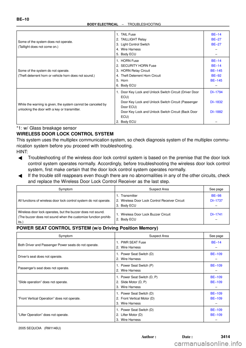
2005 SEQUOIA (RM1146U) Some of the system does not operate.
(Taillight does not come on.)
1. TAIL Fuse
2. TAILLIGHT Relay
3. Light Control Switch
4. Wire Harness
5. Body ECUBE±14
BE±27
BE±27
±
±
Some of the system do not operate.
(Theft deterrent horn or vehicle horn does not sound.)
1. HORN Fuse
2. SECURITY HORN Fuse
3. HORN Relay Circuit
4. Theft Deterrent Horn Circuit
5. Horn
6. Body ECUBE±14
BE±14
BE±145
BE±92
BE±145
±
While the warning is given, the system cannot be canceled by
unlocking the door with a key or transmitter.
1. Door Key Lock and Unlock Switch Circuit (Driver Door
ECU)
Door Key Lock and Unlock Switch Circuit (Passenger
Door ECU)
Door Key Lock and Unlock Switch Circuit (Back Door
ECU)
2. Body ECUDI±1794
DI±1832
DI±1882
±
*1: w/ Glass breakage sensor
WIRELESS DOOR LOCK CONTROL SYSTEM
This system uses the multiplex communication system, so check diagnosis system of the multiplex commu-
nication system before you proceed with troubleshooting.
HINT:
�Troubleshooting of the wireless door lock control system is based on the premise that the door lock
control system operates normally. Accordingly, before troubleshooting the wireless door lock control
system, first make certain that the door lock control system operates normally.
�If the trouble still reappears even though there are no abnormalities in any of the other circuits, check
and replace the Wireless Door Lock Control Receiver as the last step.
SymptomSuspect AreaSee page
All functions of wireless door lock control system do not operate.
1. Transmitter
2. Wireless Door Lock Control Receiver Circuit
3. Body ECUBE±98
DI±1737
±
Wireless door lock operates, but the buzzer does not sound.
(The buzzer does not sound when the customize function prohib-
its.)1. Wireless Door Lock Buzzer Circuit
2. Body ECUDI±1741
±
POWER SEAT CONTROL SYSTEM (w/o Driving Position Memory)
SymptomSuspect AreaSee page
Both Driver and Passenger Power seats do not operate.1. PWR SEAT Fuse
2. Wire HarnessBE±14
±
Driver's seat does not operate.1. Power Seat Switch (D)
2. Wire HarnessBE±109
±
Passenger's seat does not operate.1. Power Seat Switch (P)
2. Wire HarnessBE±109
±
ºSlide operationº does not operate.
1. Power Seat Switch (D, P)
2. Slide Motor (D, P)
3. Wire HarnessBE±109
BE±109
±
ºFront Vertical Operationº does not operate.
1. Power Seat Switch (D)
2. Front Vertical Motor (D)
3. Wire HarnessBE±109
BE±109
±
ºLifter Operationº does not operate.
1. Power Seat Switch (D)
2. Lifter Motor (D)
3. Wire HarnessBE±109
BE±109
±
Page 3423 of 4323

± BODY ELECTRICALTROUBLESHOOTING
BE±11
3415 Author�: Date�:
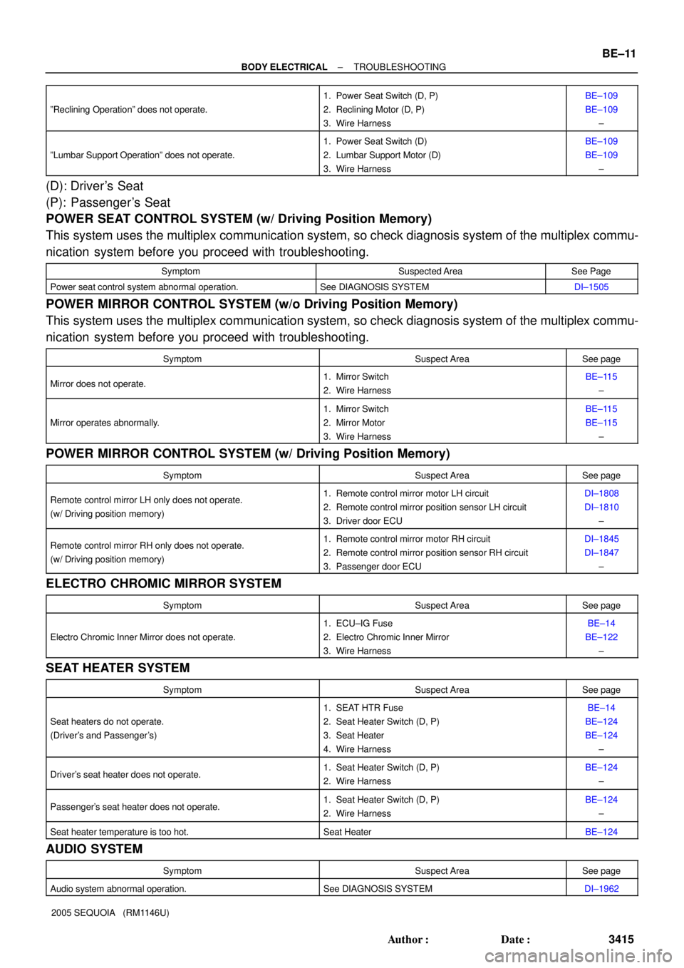
2005 SEQUOIA (RM1146U) ºReclining Operationº does not operate.
1. Power Seat Switch (D, P)
2. Reclining Motor (D, P)
3. Wire HarnessBE±109
BE±109
±
ºLumbar Support Operationº does not operate.
1. Power Seat Switch (D)
2. Lumbar Support Motor (D)
3. Wire HarnessBE±109
BE±109
±
(D): Driver's Seat
(P): Passenger's Seat
POWER SEAT CONTROL SYSTEM (w/ Driving Position Memory)
This system uses the multiplex communication system, so check diagnosis system of the multiplex commu-
nication system before you proceed with troubleshooting.
SymptomSuspected AreaSee Page
Power seat control system abnormal operation.See DIAGNOSIS SYSTEMDI±1505
POWER MIRROR CONTROL SYSTEM (w/o Driving Position Memory)
This system uses the multiplex communication system, so check diagnosis system of the multiplex commu-
nication system before you proceed with troubleshooting.
SymptomSuspect AreaSee page
Mirror does not operate.1. Mirror Switch
2. Wire HarnessBE±115
±
Mirror operates abnormally.
1. Mirror Switch
2. Mirror Motor
3. Wire HarnessBE±115
BE±115
±
POWER MIRROR CONTROL SYSTEM (w/ Driving Position Memory)
SymptomSuspect AreaSee page
Remote control mirror LH only does not operate.
(w/ Driving position memory)1. Remote control mirror motor LH circuit
2. Remote control mirror position sensor LH circuit
3. Driver door ECUDI±1808
DI±1810
±
Remote control mirror RH only does not operate.
(w/ Driving position memory)1. Remote control mirror motor RH circuit
2. Remote control mirror position sensor RH circuit
3. Passenger door ECUDI±1845
DI±1847
±
ELECTRO CHROMIC MIRROR SYSTEM
SymptomSuspect AreaSee page
Electro Chromic Inner Mirror does not operate.
1. ECU±IG Fuse
2. Electro Chromic Inner Mirror
3. Wire HarnessBE±14
BE±122
±
SEAT HEATER SYSTEM
SymptomSuspect AreaSee page
Seat heaters do not operate.
(Driver's and Passenger's)
1. SEAT HTR Fuse
2. Seat Heater Switch (D, P)
3. Seat Heater
4. Wire HarnessBE±14
BE±124
BE±124
±
Driver's seat heater does not operate.1. Seat Heater Switch (D, P)
2. Wire HarnessBE±124
±
Passenger's seat heater does not operate.1. Seat Heater Switch (D, P)
2. Wire HarnessBE±124
±
Seat heater temperature is too hot.Seat HeaterBE±124
AUDIO SYSTEM
SymptomSuspect AreaSee page
Audio system abnormal operation.See DIAGNOSIS SYSTEMDI±1962
Page 3425 of 4323
± BODY ELECTRICALTROUBLESHOOTING
BE±13
3417 Author�: Date�:
2005 SEQUOIA (RM1146U)
BACK DOOR POWER WINDOW CONTROL SYSTEM
This system uses the multiplex communication system, so check diagnosis system of the multiplex commu-
nication system before you proceed with troubleshooting.
SymptomSuspect AreaSee page
Back door power window does not operate.
1. Back Door Power Window Motor Circuit
2. Window Pulse Sensor Circuit
3. Rear Wiper Motor Circuit
4. Back Door Control Light Switch Circuit
5. Back Door ECU
6. Body ECUIN±35
DI±1877
DI±1880
DI±1864
±
±
TRAILER TOWING
SymptomSuspect AreaSee page
Trailer towing does not operate.
1. TOWING Fuse
2. TOWING TAIL Fuse
3. TOWING BRK Fuse
4. TOWING TAIL Relay
5. BATT CHARGE Relay
6. Towing Converter Relay
7. Brake Controller
8. Wire HarnessBE±14
BE±14
BE±14
BE±148
BE±148
BE±148
BE±148
±
Page 3441 of 4323

I01255
1
2 3 4
From Back Side:
I01254
Wire Harness Side:
4 3 2 1
± BODY ELECTRICALHEADLIGHT AND TAILLIGHT SYSTEM
BE±29
3433 Author�: Date�:
2005 SEQUOIA (RM1146U)
12. Connector connected:
INSPECT AUTOMATIC LIGHT CONTROL SENSOR
CIRCUIT
Connect the wire harness side connector to the sensor and in-
spect wire harness side connector from the back side, as shown
in the table.
HINT:
�Ignition switch ON.
�Light control switch AUTO.
�Vehicle's surroundings are bright.
Tester connectionConditionSpecified condition
3 ± GroundConstantContinuity
1 ± GroundIgnition switch LOCK or ACCNo voltage
1 ± GroundIgnition switch ON9.5 V or more
3 ± 4Vehicle is under the direct sun light.
(Sensor is not covered)5.2 ± 9.0 V
3 ± 4Sensor is coveredBelow 0.8 V
If circuit is as specified, try replacing the sensor with a new one.
If the circuit is not as specified, inspect the circuit connected to
other parts.
13. Connector disconnected:
INSPECT AUTOMATIC LIGHT CONTROL SENSOR
CIRCUIT
Disconnect the connector from the sensor and inspect the con-
nector on the wire harness side, as shown in the table.
Tester connectionConditionSpecified condition
3 ± GroundConstantContinuity
1 ± GroundIgnition switch OFFNo voltage
1 ± GroundIgnition switch ONBattery positive voltage
4 ± GroundIgnition switch LOCK or ACCNo voltage
4 ± GroundIgnition switch ON5.2 ± 9.0 V
If the circuit is not as specified, inspect the circuit connected to
other parts.
Page 3489 of 4323

BE2MN±01
± BODY ELECTRICALBACK DOOR POWER WINDOW CONTROL SYSTEM
BE±77
3481 Author�: Date�:
2005 SEQUOIA (RM1146U)
ADJUSTMENT
1. RESET (INITIALIZE) POWER WINDOW REGULATOR MOTOR
NOTICE:
Resetting the power window regulator motor (initializing the pulse sensor) is necessary if: 1) the bat-
tery terminal cable is disconnected; 2) the back door ECU, wire harness, power window regulator
switch, power window regulator assembly and power window regulator motor are replaced or re-
moved/installed; or 3) the P/W fuse is replaced or removed. If resetting is not performed, the master
switch assembly will not be able to operate the AUTO operation function, jam protection function and
remote operation function.
(a) Turn the ignition switch ON.
(b) Open the power window halfway by pressing the power window switch.
(c) Fully pull up on the switch until the power window is fully closed and continue to hold the switch for
at least 1 second.
(d) Check that the AUTO UP/DOWN function operates normally.
If the AUTO UP/DOWN function operates normally, reset operations are complete. If abnormal, follow the
steps (e) to (g) below.
(e) Disconnect the negative battery terminal cable for 10 seconds.
(f) Connect the battery terminal cable.
(g) Perform the steps (a) to (d) again.
Page 3678 of 4323

BO4SA±01
H24327
H24326
H24325
± BODYFRONT SEAT (Power Adjuster Type)
BO±117
3670 Author�: Date�:
2005 SEQUOIA (RM1146U)
REASSEMBLY
CAUTION:
Wear safety gloves, because the sharp edges and surfaces
of the seat frame may cause injury to the hands.
HINT:
�The procedures listed below are for the LH side.
�A bolt without a torque specification is shown in the stan-
dard bolt chart (see page SS±2).
1. Driver 's seat:
INSTALL SEAT POSITION SENSOR
(SEE PAGE RS±108)
2. INSTALL VERTICAL ADJUSTER BRACKET INNER
AND OUTER COVERS
(a) Install the vertical adjuster bracket inner cover with the
screw.
(b) Perform the same procedure on the other side.
3. INSTALL RH AND LH SEATBACK SHIELDS
(a) Install the RH seatback shield with the 2 screws.
(b) Perform the same procedure on the other side.
4. INSTALL RH AND LH RECLINING ADJUSTER INSIDE
COVERS
(a) Connect the wire harness clamp.
(b) Install the RH reclining adjuster inside cover with the
screw.
(c) Perform the same procedure on the other side.
5. INSTALL LUMBAR SUPPORT ADJUSTER
(a) Install a new bushing to the lumbar support adjuster.
(b) Install the lumbar support adjuster with the 2 screws.
Page 3833 of 4323
I21430
AC1M1±05
AC±98
± AIR CONDITIONINGCONDENSER FAN
3825 Author�: Date�:
2005 SEQUOIA (RM1146U)
REMOVAL
REMOVE CONDENSER FAN
(a) Disconnect the 2 connectors.
(b) Disconnect the wire harness clamp.
(c) Remove the ambient temperature sensor.
(d) Remove the 4 bolts and condenser fan with the fan
shroud.