Page 3032 of 4323

INSTALLATION
1. INSTALL STEERING KNUCKLE
(a) 4WD:
Insert the drive shaft into the axle hub and temp")
SA23J±05
SA±28
± SUSPENSION AND AXLEFRONT AXLE HUB
3024 Author�: Date�:
2005 SEQUOIA (RM1146U)
INSTALLATION
1. INSTALL STEERING KNUCKLE
(a) 4WD:
Insert the drive shaft into the axle hub and temporarily tighten the nut.
NOTICE:
Be careful not to damage the oil seal and drive shaft boot.
(b) Connect the steering knuckle to the upper suspension arm.
(c) Install the nut and a new cotter pin.
If the holes for the cotter pin are not aligned, tighten the nut further up to 60°.
Torque: 105 N´m (1,100 kgf´cm, 77 ft´lbf)
2. CONNECT LOWER BALL JOINT
Connect the lower ball joint to the steering knuckle with the 4 bolts.
Torque: 65 N´m (663 kgf´cm, 48 ft´lbf)
3. INSTALL SHOCK ABSORBER (See page SA±70)
4. INSTALL BRAKE CALIPER
(a) Install the disc, brake caliper and 2 bolts.
Torque: 123 N´m (1,250 kgf´cm, 90 ft´lbf)
(b) Install the brake line clamp to the steering knuckle with the bolt.
Torque: 28 N´m (285 kgf´cm, 21 ft´lbf)
5. CONNECT SPEED SENSOR AND WIRE HARNESS CLAMP
Connect the speed sensor and wire harness clamp to the steering knuckle with the 2 bolts.
Torque: 8.0 N´m (82 kgf´cm, 71 ft´lbf)
6. 4WD:
INSTALL DRIVE SHAFT LOCK NUT
(a) While applying the brakes, tighten the nut.
Torque: 235 N´m (2,400 kgf´cm, 173 ft´lbf)
(b) Install the lock cap and a new cotter pin.
If the holes for the cotter pin are not aligned, tighten the nut further up to 60°.
7. INSTALL GREASE CAP
8. INSTALL FRONT WHEEL
Torque: 110 N´m (1,150 kgf´cm, 83 ft´lbf)
9. DEPRESS BRAKE PEDAL SEVERAL TIMES
10. CHECK FRONT WHEEL ALIGNMENT (See page SA±4)
11. CHECK SPEED SENSOR SIGNAL (See page DI±899)
12. PERFORM ZERO POINT CALIBRATION OF STEERING ANGLE, MASTER CYLINDER PRES-
SURE, YAW RATE AND DECELERATION SENSORS (See page DI±897)
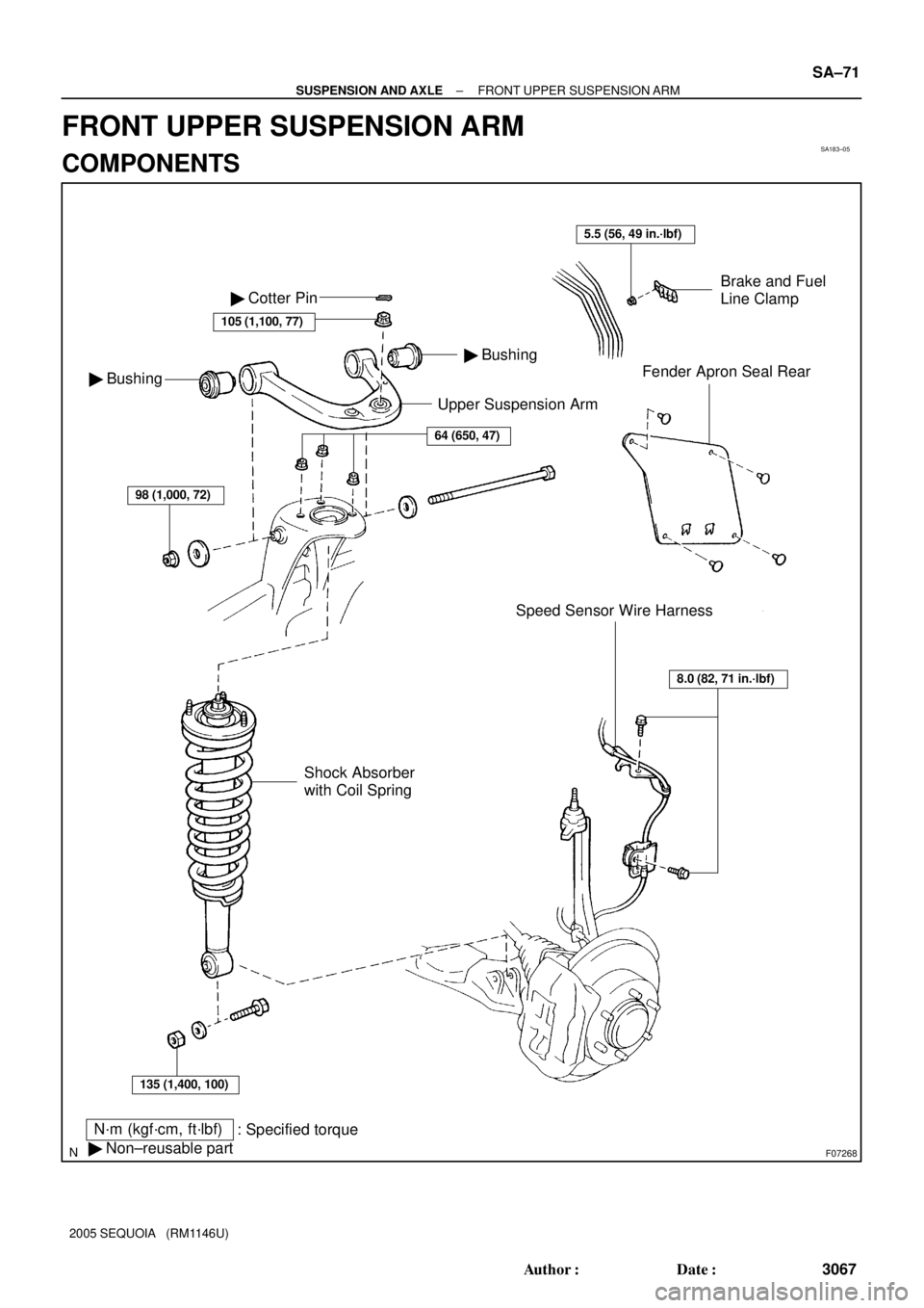
Page 3075 of 4323
SA183±05
F07268
Upper Suspension Arm
N´m (kgf´cm, ft´lbf)
: Specified torque
� Non±reusable part
Brake and Fuel
Line Clamp
Fender Apron Seal Rear
Speed Sensor Wire Harness � Bushing
� Bushing � Cotter Pin
105 (1,100, 77)
64 (650, 47)
98 (1,000, 72)
135 (1,400, 100)
Shock Absorber
with Coil Spring
8.0 (82, 71 in.´lbf)
5.5 (56, 49 in.´lbf)
± SUSPENSION AND AXLEFRONT UPPER SUSPENSION ARM
SA±71
3067 Author�: Date�:
2005 SEQUOIA (RM1146U)
FRONT UPPER SUSPENSION ARM
COMPONENTS
Page 3076 of 4323
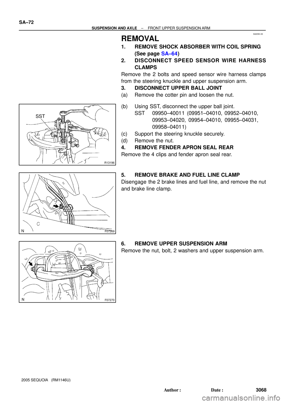
SA23W±03
R13196
SST
F07269
F07270
SA±72
± SUSPENSION AND AXLEFRONT UPPER SUSPENSION ARM
3068 Author�: Date�:
2005 SEQUOIA (RM1146U)
REMOVAL
1. REMOVE SHOCK ABSORBER WITH COIL SPRING
(See page SA±64)
2. DISCONNECT SPEED SENSOR WIRE HARNESS
CLAMPS
Remove the 2 bolts and speed sensor wire harness clamps
from the steering knuckle and upper suspension arm.
3. DISCONNECT UPPER BALL JOINT
(a) Remove the cotter pin and loosen the nut.
(b) Using SST, disconnect the upper ball joint.
SST 09950±40011 (09951±04010, 09952±04010,
09953±04020, 09954±04010, 09955±04031,
09958±04011)
(c) Support the steering knuckle securely.
(d) Remove the nut.
4. REMOVE FENDER APRON SEAL REAR
Remove the 4 clips and fender apron seal rear.
5. REMOVE BRAKE AND FUEL LINE CLAMP
Disengage the 2 brake lines and fuel line, and remove the nut
and brake line clamp.
6. REMOVE UPPER SUSPENSION ARM
Remove the nut, bolt, 2 washers and upper suspension arm.
Page 3078 of 4323

INSTALLATION
1. INSTALL UPPER SUSPENSION ARM
Install the upper suspension arm with the 2")
SA187±06
SA±74
± SUSPENSION AND AXLEFRONT UPPER SUSPENSION ARM
3070 Author�: Date�:
2005 SEQUOIA (RM1146U)
INSTALLATION
1. INSTALL UPPER SUSPENSION ARM
Install the upper suspension arm with the 2 washers, bolt and nut.
Torque: 98 N´m (1,000 kgf´cm, 72 ft´lbf)
HINT:
After stabilizing the suspension, torque the nut.
2. INSTALL BRAKE AND FUEL LINE CLAMP
Torque: 5.5 N´m (56 kgf´cm, 49 in.´lbf)
3. INSTALL FENDER APRON SEAL REAR
4. CONNECT UPPER BALL JOINT
(a) Connect the upper ball joint to the upper suspension arm.
(b) Install the nut and a new cotter pin.
If the holes for the cotter pin are not aligned, tighten the nut further up to 60°.
Torque: 105 N´m (1,100 kgf´cm, 77 ft´lbf)
5. CONNECT SPEED SENSOR WIRE HARNESS CLAMPS
Torque: 8.0 N´m (82 kgf´cm, 71 in.´lbf)
6. INSTALL SHOCK ABSORBER WITH COIL SPRING (See page SA±70)
7. CHECK FRONT WHEEL ALIGNMENT (See page SA±4)
8. PERFORM ZERO POINT CALIBRATION OF STEERING ANGLE, MASTER CYLINDER PRES-
SURE, YAW RATE AND DECELERATION SENSORS (See page DI±897)
Page 3150 of 4323
SA17B±05
F14298
Speed Sensor
Wire Harness
Lower Control Arm
N´m (kgf´cm, ft´lbf) : Specified torque
Upper Control Arm
140 (1,428, 103)
140 (1,428, 103)
28 (286, 21)
130 (1,326, 96)
26 (265, 19)
Parking Brake Cable130 (1,326, 96)
Brake Line
Bracket
SA±146
± SUSPENSION AND AXLEREAR UPPER AND LOWER CONTROL ARM
3142 Author�: Date�:
2005 SEQUOIA (RM1146U)
REAR UPPER AND LOWER CONTROL ARM
COMPONENTS
Page 3151 of 4323
SA24J±02
F14299
F14300
± SUSPENSION AND AXLEREAR UPPER AND LOWER CONTROL ARM
SA±147
3143 Author�: Date�:
2005 SEQUOIA (RM1146U)
REMOVAL
1. REMOVE REAR WHEEL
Torque: 110 N´m (1,150 kgf´cm, 83 ft´lbf)
2. SUPPORT REAR AXLE HOUSING WITH JACK
3. REMOVE UPPER CONTROL ARM
(a) Disconnect the speed sensor wire harness.
(b) Remove the bolt and brake line bracket.
Torque: 28 N´m (286 kgf´cm, 21 ft´lbf)
(c) Remove the 2 nuts, washers, bolts and upper control arm.
Torque: 140 N´m (1,428 kgf´cm, 103 ft´lbf)
HINT:
At the time of installation, after stabilizing the suspension,
torque the nuts.
4. REMOVE LOWER CONTROL ARM
(a) Remove the bolt and parking brake cable bracket.
Torque: 26 N´m (265 kgf´cm, 19 ft´lbf)
(b) Remove the 2 nuts, bolts and lower control arm.
Torque: 130 N´m (1,326 kgf´cm, 96 ft´lbf)
HINT:
At the time of installation, after stabilizing the suspension,
torque the nuts.
Page 3173 of 4323
SA2D3±01
F16835Matchmarks
F16836
± SUSPENSION AND AXLEREAR HEIGHT CONTROL SENSOR
SA±169
3165 Author�: Date�:
2005 SEQUOIA (RM1146U)
REMOVAL
1. DISCONNECT CONNECTOR
2. DISCONNECT HEIGHT CONTROL SENSOR LINK
(a) Put matchmarks on the height control sensor link and
bracket.
(b) Remove the nut and disconnect the sensor link.
Torque: 5.4 N´m (55 kgf´cm, 48 in.´lbf)
3. REMOVE REAR HEIGHT CONTROL SENSOR
(a) Disconnect the wire harness clamp.
(b) Remove the 2 bolts and rear height control sensor.
Torque: 29 N´m (300 kgf´cm, 21 ft´lbf)
Page 3190 of 4323
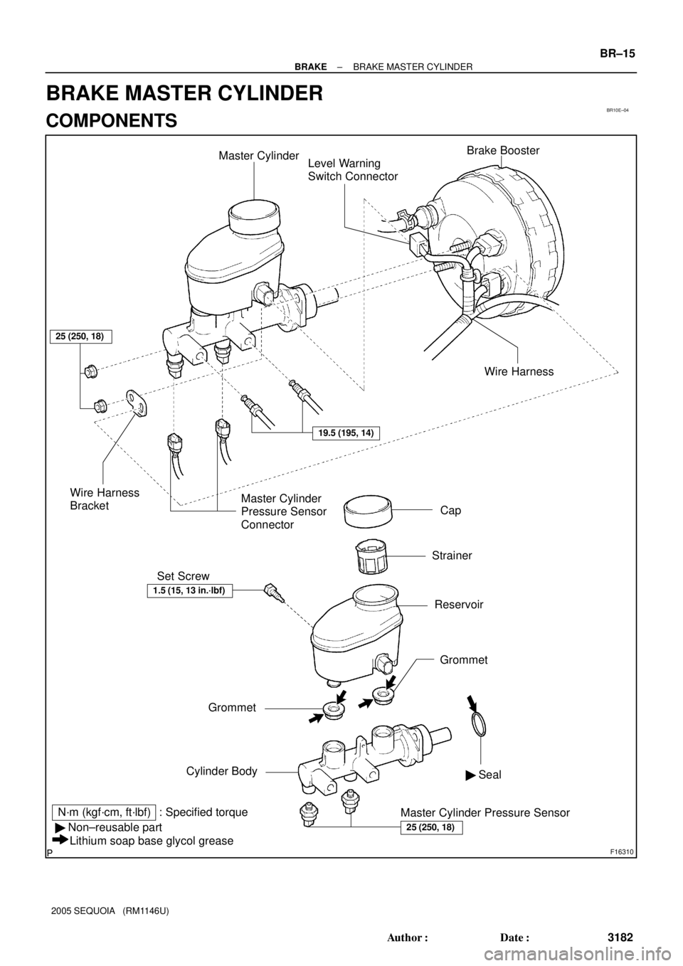
BR10E±04
F16310
Master Cylinder
Level Warning
Switch ConnectorBrake Booster
Cap
Strainer
Reservoir Set Screw
Grommet
Cylinder Body
N´m (kgf´cm, ft´lbf) : Specified torque
� Non±reusable part
Lithium soap base glycol greaseWire Harness
BracketMaster Cylinder
Pressure Sensor
Connector
Master Cylinder Pressure Sensor� Seal
25 (250, 18)
25 (250, 18)
19.5 (195, 14)
Wire Harness
1.5 (15, 13 in.´lbf)
Grommet
± BRAKEBRAKE MASTER CYLINDER
BR±15
3182 Author�: Date�:
2005 SEQUOIA (RM1146U)
BRAKE MASTER CYLINDER
COMPONENTS
 : Specified torque
Upper Control Arm
140 (1,428, 103)
140 (1,428, 103)
28 (286, 21)
130 (1,326, 96)
26 (265, 19)
Pa")