Page 2556 of 4323
I28852
HOTCOOL
4
532 4
5
2
3
1
1
DI±2354
± DIAGNOSTICSAIR CONDITIONING SYSTEM
2548 Author�: Date�:
2005 SEQUOIA (RM1146U)
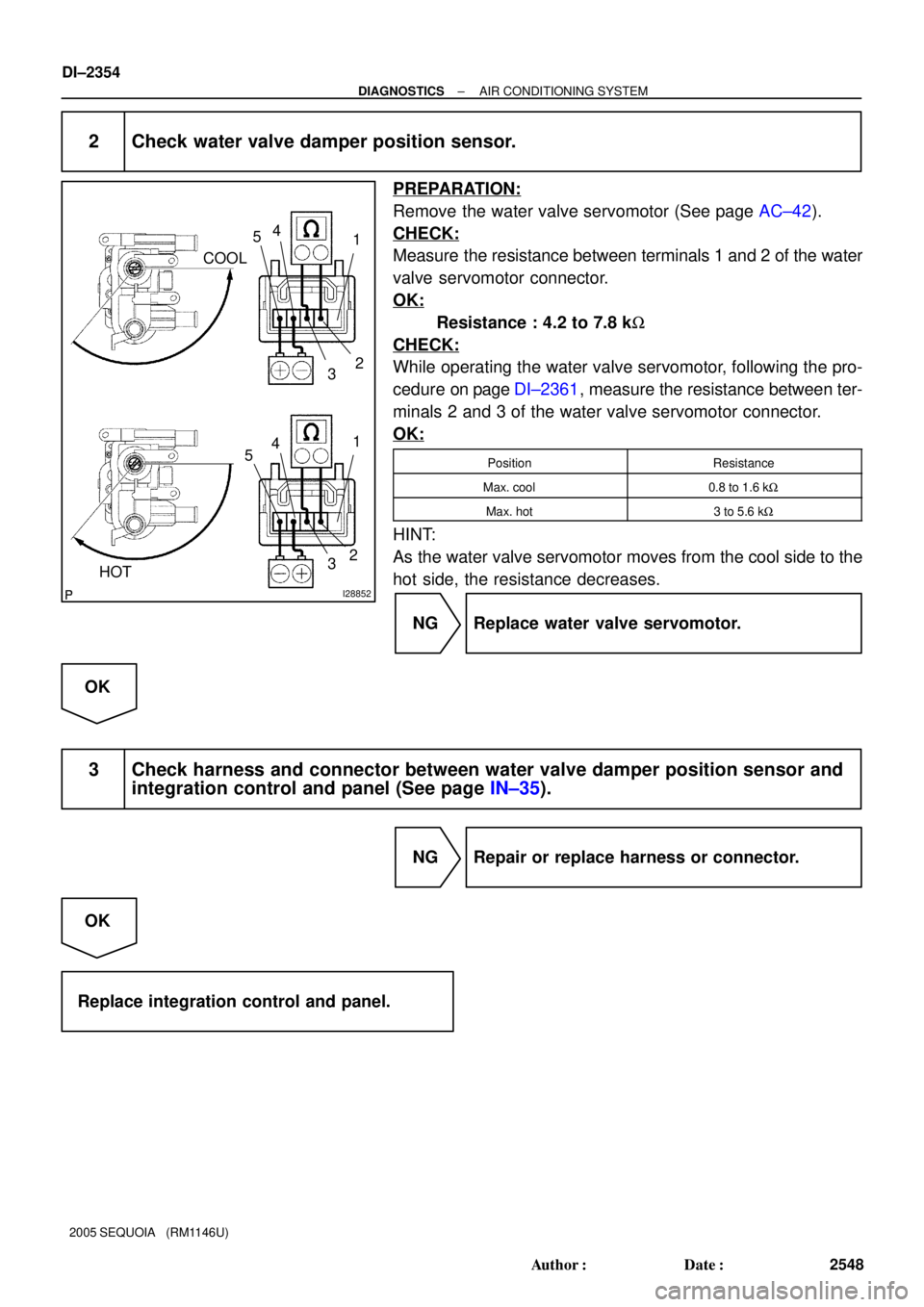
2 Check water valve damper position sensor.
PREPARATION:
Remove the water valve servomotor (See page AC±42).
CHECK:
Measure the resistance between terminals 1 and 2 of the water
valve servomotor connector.
OK:
Resistance : 4.2 to 7.8 kW
CHECK:
While operating the water valve servomotor, following the pro-
cedure on page DI±2361, measure the resistance between ter-
minals 2 and 3 of the water valve servomotor connector.
OK:
PositionResistance
Max. cool0.8 to 1.6 kW
Max. hot3 to 5.6 kW
HINT:
As the water valve servomotor moves from the cool side to the
hot side, the resistance decreases.
NG Replace water valve servomotor.
OK
3 Check harness and connector between water valve damper position sensor and
integration control and panel (See page IN±35).
NG Repair or replace harness or connector.
OK
Replace integration control and panel.
Page 2557 of 4323
I28839
A17 Air Mix Damper
Control Servomotor (Front)
1
210
9AMH
AMC Integration Control and Panel
R±L
W±LI20 MHOT
I20 MCOOL
± DIAGNOSTICSAIR CONDITIONING SYSTEM
DI±2355
2549 Author�: Date�:
DTC 41 Front Air Mix Damper Control Servomotor
Circuit
CIRCUIT DESCRIPTION
The front air mix damper control servomotor is controlled by the integration control and panel and moves
the air mix damper to the desired position.
DTC No.Detection ItemTrouble Area
41
Air mix damper position sensor value does not change even if
integration control and panel operates air mix damper control
servomotor.
�Front air mix damper control servomotor
�Front air mix damper position sensor
�Harness or connector between front air mix position sensor
and integration control and panel
�Harness or connector between air mix damper control servo-
motor and integration control and panel
�Integration control and panel
WIRING DIAGRAM
DI3FI±15
Page 2560 of 4323
I28840
A16 Air Inlet Damper
Control Servomotor
520
8AIR
AIF Integration Control and Panel
G±W
I20
R 4
REC
FRS
I20 DI±2358
± DIAGNOSTICSAIR CONDITIONING SYSTEM
2552 Author�: Date�:
DTC 42 Air Inlet Damper Control Servomotor Circuit
CIRCUIT DESCRIPTION
The air inlet damper control servomotor is controlled by the integration control and panel and moves the air
inlet damper to the desired position.
DTC No.Detection itemTrouble Area
�Air inlet damper control servomotor
�Air inlet damper position sensor
42
Air inlet damper position sensor value does not change even if
integration control and panel operated air inlet damper control
servomotor
�Harness or connector between air inlet damper control servo-
motor and integration control and panel
�Harness or connector between air inlet damperposition sen-servomotor.�Harness or connector between air inlet damper position sen-
sor and integration control and panel
�Integration control and panel
WIRING DIAGRAM
DI3FJ±14
Page 2563 of 4323

R±G L±B
28
10 L±B w/ Rear A/C:
7
M.COOL
M.HOTI21 IJ3 BH1
± DIAGNOSTICSAIR CONDITIONING")
I28841
Integration Control
and Panel
5
IJ3
I219
RrAMC
RrAMH L±B
BH13
4
R±G R±G A34
A/C Water Valve (Rear)
R±G L±B
28
10 L±B w/ Rear A/C:
7
M.COOL
M.HOTI21 IJ3 BH1
± DIAGNOSTICSAIR CONDITIONING SYSTEM
DI±2361
2555 Author�: Date�:
2005 SEQUOIA (RM1146U)
DTC 47 Water Valve Damper Control Servomotor
Circuit
CIRCUIT DESCRIPTION
The water valve damper control servomotor is controlled by the integration control and panel and moves the
water valve damper to the desired position.
DTC No.Detection ItemTrouble Area
47
Water valve damper position sensor value does not change
even if integration control and panel operates water valve
damper control servomotor.
�Water valve damper control servomotor
�Water valve damper position sensor
�Harness or connector between water valve damper control
servomotor and integration control and panel
�Harness or connector between water valve damper position
sensor and integration control and panel
�Integration control and panel
WIRING DIAGRAM
DI936±04
Page 2923 of 4323
ATF TEMPERATURE SENSOR
AT±7
2915 Author�: Date�:
2005 SEQUOI")
D13867
AT134±01
D12704
Orange
Blue
Clamp
ClampBolt
Bolt
D12739
D12704
Orange
Blue
Clamp
Clamp
A B
± AUTOMATIC TRANSMISSION (A750E, A750F)ATF TEMPERATURE SENSOR
AT±7
2915 Author�: Date�:
2005 SEQUOIA (RM1146U)
ATF TEMPERATURE SENSOR
ON±VEHICLE REPAIR
1. DRAIN AUTOMATIC TRANSMISSION FLUID
(a) Remove the drain plug and gasket, and drain the ATF.
(b) Install a new gasket and the drain plug.
Torque: 20 N´m (204 kgf´cm, 15 ft´lbf)
2. REMOVE OIL PAN (See page AT±10)
3. REMOVE OIL STRAINER (See page AT±10)
4. REMOVE ATF TEMPERATURE SENSOR
(a) Disconnect the 7 solenoid valve connectors.
(b) Remove the 2 bolts, clamps and ATF temperature sen-
sors.
(c) Disconnect the transmission wire connector.
(d) Remove the bolt and the transmission wire harness.
5. INSTALL ATF TEMPERATURE SENSOR
(a) Install the transmission wire harness.
(b) Install the bolt.
Torque: 5.4 N´m (55 kgf´cm, 48 in.´lbf)
(c) Connect the transmission wire connector.
(d) Connect the 7 solenoid valve connectors.
(e) Install the 2 ATF temperature sensors and clamps to the
valve body with the 2 bolts.
HINT:
In order to install the ATF temperature sensors properly, check
the wire harness color prior to installation.
Torque:
A: 11 N´m (112 kgf´cm, 8 ft´lbf)
B: 10 N´m (100 kgf´cm, 7 ft´lbf)
Bolt length:
Bolt A: 36 mm (1.42 in.)
Bolt B: 12 mm (0.47 in.)
Sensor wire harness:
Wire harnessColor
for linear controlOrange
for oil temp. warning lampBlue
6. INSTALL OIL STRAINER (See page AT±10)
Page 2928 of 4323
VALVE BODY ASSEMBLY
2920 Author�: Date�:
2005 SEQUOIA (RM1146U)
(b) Install the 19 bolts and th")
D12705
D12704
Orange
Blue
Clamp
Clamp
A B
D12703
D13866
AT±12
± AUTOMATIC TRANSMISSION (A750E, A750F)VALVE BODY ASSEMBLY
2920 Author�: Date�:
2005 SEQUOIA (RM1146U)
(b) Install the 19 bolts and the valve body.
Torque: 11 N´m (112 kgf´cm, 8 ft´lbf)
Bolt length:
Bolt A: 25 mm (0.98 in.)
Bolt B: 36 mm (1.42 in.)
10. INSTALL TEMPERATURE SENSOR
(a) Connect the 7 solenoid valve connectors.
(b) Install the 2 temperature sensors and clamps to the valve
body with the 2 bolts.
HINT:
In order to install the ATF temperature sensors properly, check
the wire harness color prior to installation.
Torque:
A: 11 N´m (112 kgf´cm, 8 ft´lbf)
B: 10 N´m (100 kgf´cm, 7 ft´lbf)
Bolt length:
Bolt A: 36 mm (1.42 in.)
Bolt B: 12 mm (0.47 in.)
Sensor wire harness:
Wire harnessColor
for linear controlOrange
for oil temp. warning lampBlue
11. INSTALL OIL STRAINER
(a) Install a new O±ring.
(b) Install the oil strainer with the 4 bolts.
Torque: 10 N´m (100 kgf´cm, 7 ft´lbf)
12. INSTALL OIL PAN
HINT:
Remove any packing material, and be careful not to spill oil on
the contacting surfaces of the transmission case and the oil
pan.
Using a new gasket, install the oil pan with the 20 bolts.
Torque: 4.4 N´m (45 kgf´cm, 39 in´lbf)
Page 2948 of 4323

TROUBLESHOOTING
PROBLEM SYMPTOMS TABLE
Use the table below to help find the cause of the problem. The numbers i")
TR04H±04
TR±2
± TRANSFERTROUBLESHOOTING
2940 Author�: Date�:
2005 SEQUOIA (RM1146U)
TROUBLESHOOTING
PROBLEM SYMPTOMS TABLE
Use the table below to help find the cause of the problem. The numbers indicate the priority of the likely cause
of the problem. Check each part in order. If necessary, replace these parts.
SymptomSuspected AreaSee page
Noise
1. Oil (Level low)
2. Oil (Wrong)
3. Transfer faultyTR±5
TR±5
TR±7
Oil leakage
1. Oil (Level too high)
2. Gasket (Damaged)
3. Oil seal (Worn or damaged)
4. O±ring (Worn or damaged)TR±5
TR±7
TR±16
TR±7
Tight corner brakingCenter differential or transfer faultyTR±7
Shift from 2WD (H) to 4WD (H) impossible
1. 4WD fuse
2. Wire harness
3. Vehicle speed sensor
4. 2WD/4HI switch
5. 4WD indicator light
6. Actuator assembly
7. A.D.D. control system
8. 4WD control ECU
9. Transfer assembly±
±
BE±55
TR±39
TR±39
TR±39
SA±61
TR±39
TR±3
Shift from 2WD (H) to 4WD (L4) impossible
1. 4LO switch
2. Wire harness
3. 4WD control ECUTR±39
±
TR±39
Shift from 4WD (H) to 4WD (L4) impossible
1. 4LO switch
2. Wire harness
3. 4WD control ECUTR±9
±
TR±39
Shift from 4WD (H) to 2WD (H) impossible
1. 4WD fuse
2. Wire harness
3. 4WD indicator light
4. Actuator assembly
5. A.D.D. control system
6. 4WD control ECU
7. Transfer assembly±
±
TR±39
TR±39
SA±61
TR±39
TR±3
Shift from 4WD (L4) to 2WD (H) impossible
1. 2WD/4HI switch
2. Wire harness
3. 4WD control ECUTR±39
±
TR±39
Shift from 4WD (L4) to 4WD (H) impossible
1. 2WD/4HI switch
2. Wire harness
3. 4WD control ECUTR±39
±
TR±39
Page 3026 of 4323
SA23I±04
R13426
F07263
F07264
F07265
SA±22
± SUSPENSION AND AXLEFRONT AXLE HUB
3018 Author�: Date�:
2005 SEQUOIA (RM1146U)
REMOVAL
1. REMOVE FRONT WHEEL
2. REMOVE GREASE CAP
Using a screwdriver and hammer, remove the grease cap.
3. 4WD:
DISCONNECT DRIVE SHAFT
(a) Remove the cotter pin and lock cap.
(b) While applying the brakes, remove the lock nut.
4. DISCONNECT SPEED SENSOR AND WIRE HARNESS
CLAMP FROM STEERING KNUCKLE
Remove the 2 bolts and disconnect the speed sensor and wire
harness clamp from the steering knuckle.
5. REMOVE BRAKE CALIPER AND DISC
(a) Remove the bolt and brake line clamp from the steering
knuckle.
(b) Remove the 2 bolts, brake caliper and disc.
NOTICE:
Do not damage the brake tube.
(c) Support the brake caliper securely.
6. REMOVE SHOCK ABSORBER (See page SA±64)
7. DISCONNECT LOWER BALL JOINT
Remove the 4 bolts and disconnect the lower ball joint.
8. REMOVE STEERING KNUCKLE
(a) Remove the cotter pin and loosen the nut.