Page 3191 of 4323
BR08U±05
F16312
F16313
BR±16
± BRAKEBRAKE MASTER CYLINDER
3183 Author�: Date�:
2005 SEQUOIA (RM1146U)
REMOVAL
1. DRAW OUT FLUID WITH SYRINGE
NOTICE:
Wash the brake fluid off immediately if it comes into con-
tact with any painted surface.
2. DISCONNECT LEVEL WARNING SWITCH CONNEC-
TOR
3. DISCONNECT 2 MASTER CYLINDER PRESSURE
SENSOR CONNECTORS
4. DISCONNECT WIRE HARNESS
Using a clip remover, disconnect the wire harness from the wire
harness bracket.
5. DISCONNECT BRAKE LINES
Using SST, disconnect the 2 brake lines from the master cylin-
der.
SST 09023±38201
Torque: 19.5 N´m (195 kgf´cm, 14 ft´lbf)
6. REMOVE MASTER CYLINDER
(a) Remove the 2 nuts and wire harness bracket.
Torque: 25 N´m (250 kgf´cm, 18 ft´lbf)
(b) Pull out the master cylinder from the brake booster.
Page 3196 of 4323
BR10G±04
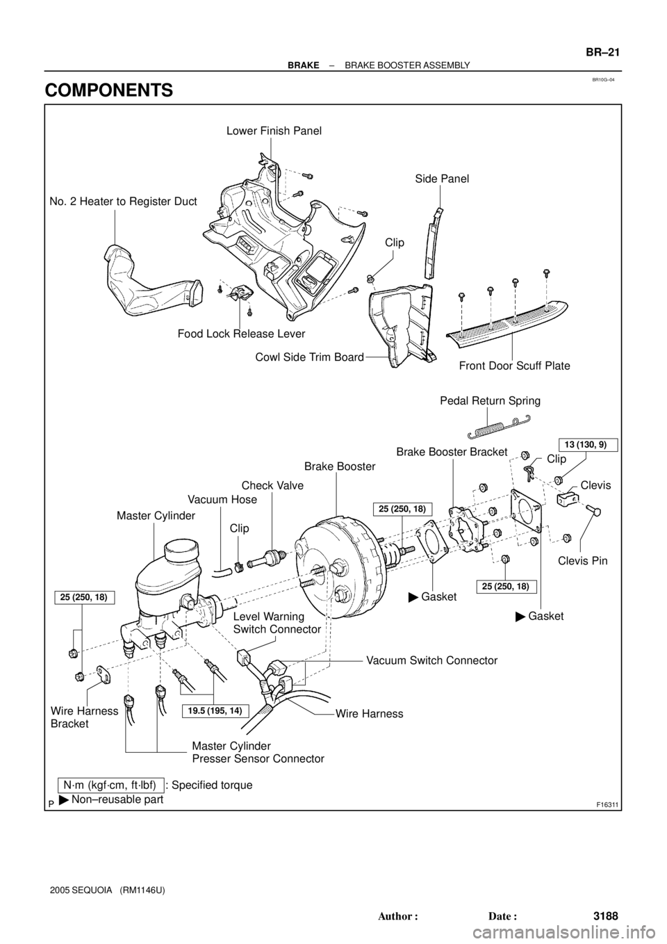
F16311
Master CylinderVacuum Hose
Level Warning
Switch ConnectorBrake Booster
� GasketClevis Pin Brake Booster Bracket Clip
: Specified torque
N´m (kgf´cm, ft´lbf)
� Non±reusable partPedal Return Spring
Wire Harness
Bracket
Lower Finish Panel
Food Lock Release Lever No. 2 Heater to Register Duct
Cowl Side Trim Board
Front Door Scuff Plate
� GasketClevis
Vacuum Switch Connector
19.5 (195, 14)
25 (250, 18)
25 (250, 18)
ClipCheck Valve
25 (250, 18)
Side Panel
Wire Harness
13 (130, 9)
Clip
Master Cylinder
Presser Sensor Connector
± BRAKEBRAKE BOOSTER ASSEMBLY
BR±21
3188 Author�: Date�:
2005 SEQUOIA (RM1146U)
COMPONENTS
Page 3231 of 4323
BR0A3±04
F08186
BR±56
± BRAKEFRONT SPEED SENSOR
3223 Author�: Date�:
2005 SEQUOIA (RM1146U)
REMOVAL
1. REMOVE FRONT WHEEL
Torque: 110 N´m (1,122 kgf´cm, 81 ft´lbf)
2. DISCONNECT SPEED SENSOR CONNECTOR
3. REMOVE SPEED SENSOR
(a) Remove the clips and 3 clamp bolts holding the sensor
harness from the frame, upper arm and steering knuckle.
Torque: 8.0 N´m (82 kgf´cm, 71 in.´lbf)
(b) Remove the bolt and speed sensor from the steering
knuckle.
Torque: 8.0 N´m (82 kgf´cm, 71 in.´lbf)
Page 3234 of 4323
BR0A6±04
F13328
± BRAKEREAR SPEED SENSOR
BR±59
3226 Author�: Date�:
2005 SEQUOIA (RM1146U)
REMOVAL
1. DISCONNECT SPEED SENSOR CONNECTOR
2. REMOVE SPEED SENSOR
(a) Remove the 6 resin clips holding the sensor wire harness.
(b) Remove the bolt and speed sensor from the axle carrier.
Torque: 8.0 N´m (82 kgf´cm, 71 in.´lbf)
Page 3410 of 4323
RS0BU±10
H23906
Front Airbag Sensor (LH)Front Airbag
Sensor (RH)Front Passenger
Airbag Assembly (RH)
Seat Belt
Pretensioner (RH)
Airbag Sensor Assembly Seat Belt Pretensioner (LH) Spiral CableCurtain Shield
Airbag Assembly (RH)
Side Airbag
Assembly (RH) (*1)
Side Airbag Sensor
Assembly (RH) (*1)
Side Airbag Assembly (LH) (*1) Side Airbag Sensor
Assembly (LH) (*1)
Curtain Shield Airbag
Assembly (LH) (*1)
Combination Meter
(Warning Light)
Steering Wheel Pad
(With Airbag)
Curtain Shield Airbag
Sensor Assembly (LH) (*1)
Curtain Shield Airbag
Sensor Assembly
(RH) (*1)RSCA OFF
Switch (*1)
Occupant Classification
ECU (*1)
(*1) w/ Side Airbag and Curtain Shield Airbag
± SUPPLEMENTAL RESTRAINT SYSTEMWIRE HARNESS AND CONNECTOR
RS±119
3402 Author�: Date�:
2005 SEQUOIA (RM1146U)
WIRE HARNESS AND CONNECTOR
LOCATION
Page 3411 of 4323
RS0BV±08
RS±120
± SUPPLEMENTAL RESTRAINT SYSTEMWIRE HARNESS AND CONNECTOR
3403 Author�: Date�:
2005 SEQUOIA (RM1146U)
INSPECTION
HINT:
The SRS wire harness is integrated with the cowl wire harness assembly. The wires for the SRS wire harness
are encased in a yellow corrugated tube and all the connectors in the system except the seat position airbag
sensor connector and occupant classification ECU connectors, colored are yellow.
1. VEHICLE NOT INVOLVED IN COLLISION
Perform a diagnostic system check (see page DI±1147).
2. VEHICLE INVOLVED IN COLLISION
(a) Perform a diagnostic system check (see page DI±1147).
(b) Check breaks in all wires of the SRS wire harness, and exposed conductors.
(c) Check if the SRS wire harness connectors are cracked or chipped.
Page 3420 of 4323

DEFOGGER SYSTEM
SymptomSuspect AreaSee page
Rear window defogger does not operate.
1. HTR Fuse
2. DEFOG Fuse
3. DE")
BE±8
± BODY ELECTRICALTROUBLESHOOTING
3412 Author�: Date�:
2005 SEQUOIA (RM1146U)
DEFOGGER SYSTEM
SymptomSuspect AreaSee page
Rear window defogger does not operate.
1. HTR Fuse
2. DEFOG Fuse
3. DEFOG Relay
4. Defogger Switch (in A/C Panel Switch)
5. Defogger Wire
6. Wire HarnessBE±14
BE±14
BE±14
BE±65
BE±65
±
Mirror defogger does not operate.
1. MIR±HTR Fuse
2. HTR Fuse
3. Mirror Heater Relay
4. Mirror Heater
5. Wire HarnessBE±14
BE±14
BE±65
BE±65
±
POWER WINDOW CONTROL SYSTEM
This system uses the multiplex communication system, so check diagnosis system of the multiplex commu-
nication system before you proceed with troubleshooting.
SymptomSuspect AreaSee page
All the power windows do not operate.
(Power door lock system is normal.)
1. POWER MAIN Relay
2. Driver Door ECU (Power Window Master Switch)
3. Body ECU
4. Wire HarnessBE±69
DI±1788
±
±
Only the driver's window does not operate.
1. Power Window Motor
2. Power Window Pulse Sensor Circuit
3. Power Window Limit Switch Circuit
4. Driver Door ECU (Power Window Master Switch)BE±69
DI±1803
DI±1800
±
ºWindow lock functionº does not operate.Driver Door ECU (Power Window Master Switch)BE±69
Only the rear LH window does not operate.
1. Power Window Motor
2. Power Window Switch
3. Body ECUBE±69
BE±69
±
Only the rear RH window does not operate.
1. Power Window Motor
2. Power Window Switch
3. Body ECUBE±69
BE±69
±
Only the front passenger's window does not operate.
1. Power Window Motor
2. Power Window Pulse Sensor Circuit
3. Power Window Limit Switch Circuit
4. Passenger Door ECUBE±69
DI±1841
DI±1838
±
The Key related power window operations do not operate with
driver side door key cylinder.
(Master switch operation is normal.)1. Door Key Lock and Unlock Switch Circuit
2. Driver Door ECU (Power Window Master Switch)DI±1791
±
º Auto up º or º Auto down º does not operate. *1
1. Power Window Pulse Sensor Circuit
2. Power Window Limit Switch Circuit
3. Driver Door ECU (Power Window Master Switch)DI±1803
DI±1800
±
*1: º Auto up º or º Auto down º may not function when the manual switch is pressed and held for 2 sec. or
more with the window glass fully open or closed. In this case, by performing a sequence of the window glass
operations (full open, fully close and then half open), the function can be restored. If not, replace the driver
door ECU or passenger door ECU.
Page 3421 of 4323

POWER DOOR LOCK CONTROL SYSTEM
This system uses the multiplex communication system, so check diagnosis system of t")
± BODY ELECTRICALTROUBLESHOOTING
BE±9
3413 Author�: Date�:
2005 SEQUOIA (RM1146U)
POWER DOOR LOCK CONTROL SYSTEM
This system uses the multiplex communication system, so check diagnosis system of the multiplex commu-
nication system before you proceed with troubleshooting.
SymptomSuspect AreaSee page
All the doors cannot be locked or unlocked.
(Power window control system is normal.)1. Door Unlock Detection Switch
2. Door Key Lock and Unlock Switch
3. Driver Door ECUBE±79
BE±79
±
Only one back lock control does not operate.
1. Back Door Lock Motor
2. Back Door Unlock Detection Switch
3. Back Door Key Lock and Unlock Switch
4. Back Door ECUBE±79
BE±79
BE±79
±
Driver door key related function does not operate.1. Door Key Lock and Unlock Switch
2. Driver Door ECUBE±79
±
Front passenger door key related function does not operate.1. Door Key Lock and Unlock Switch
2. Passenger Door ECUBE±79
±
Back door key related function does not operate.1. Door Key Lock and Unlock Switch
2. Back Door ECUBE±79
±
THEFT DETERRENT SYSTEM
This system uses the multiplex communication system, so check diagnosis system of the multiplex commu-
nication system before you proceed with troubleshooting.
SymptomSuspect AreaSee page
The theft deterrent system cannot be set.
1. Key Unlock Warning Switch Circuit
2. Door Unlock Detection Switch Circuit (Driver Door ECU)
Door Unlock Detection Switch Circuit (Passenger Door
ECU)
Door Unlock Detection Switch Circuit (Back Door ECU)
Door Unlock Detection Switch Circuit (Body ECU)
3. Engine Hood Courtesy Switch Circuit
4. Back Door Courtesy Light Switch
5. Courtesy Light Switch Circuit
6. Glass Breakage Sensor Circuit (*1)
7. Body ECUDI±1715
DI±1791
DI±1829
DI±1869
DI±1723
DI±1725
DI±1864
DI±1728
DI±1774
±
The system cannot be canceled when the ignition switch is turned
ON with a key.
1. AM1 Fuse
2. AM2 Fuse
3. Key Unlock Warning Switch Circuit
4. Ignition Switch
5. Body ECUBE±14
BE±14
DI±1715
BE±24
±
The system cannot be canceled when the back door is unlocked
with a key.
1. Back Door Unlock Detection Switch Circuit
2. Back Door Key Lock and Unlock Switch Circuit
3. Back door ECU
4. Body ECUDI±1869
DI±1882
±
±
The system does not operate when the engine hood is opened.1. Engine Hood Courtesy Switch Circuit
2. Body ECUDI±1725
±
Some of the system does not operate.
(Headlight does not come on.)
1. Bulb
2. HEAD Relay
3. DIMMER Relay
4. DRL No. 4 Relay
5. Headlight Dimmer Switch
6. Light Control Switch
7. Wire Harness
8. Body ECU±
BE±27
BE±27
BE±27
BE±27
BE±27
±
±


Front Airbag
Sensor (RH)Front Passenger
Airbag Assembly (RH)
Seat Belt
Pretensioner (RH)
Airbag Sensor Assembly Seat Belt Pretensioner (LH) Spiral CableCurtain")