Page 2541 of 4323

I28835
24
Y±B W±R
A3
A/C Magnetic Clutch
and Lock Sensor 2
1IG4
SG±TAM Integration Control
and Panel
13
I19LOCK
20
I19 Y±B W±R
J14
J/C
AA 23
Y±B
IG4
± DIAGNOSTICSAIR CONDITIONING SYSTEM
DI±2339
2533 Author�: Date�:
2005 SEQUOIA (RM1146U)
DTC 22 Compressor Lock Sensor Circuit
CIRCUIT DESCRIPTION
This sensor sends 1 pulse per engine revolution to the integration control and panel.
If the compressor speed divided by the engine speed is smaller than a predetermined value, the integration
control and panel turns the compressor OFF. The indicator flashes at about 1 second intervals.
DTC No.Detection ItemTrouble Area
22
All conditions below are detected for 3 sec. or more
(a) Engine speed: 450 rpm or more
(b) Ratio of engine to compressor speed deviates 20% or more
in comparison to normal operation.
�Compressor drive belt
�Compressor lock sensor
�Compressor
�Harness or connector between compressor lock sensor and
integration control and panel
�Integration control and panel
WIRING DIAGRAM
DIDKY±01
Page 2543 of 4323
± DIAGNOSTICSAIR CONDITIONING SYSTEM
DI±2341
2535 Author�: Date�:
2005 SEQUOIA (RM1146U)
3 Check harness and connector between compressor lock sensor and integration
control and panel (See page IN±24).
NG Repair or replace harness or connector.
OK
Replace integration control and panel.
Page 2544 of 4323
I29011
ON (Below 1.0 W) Low pressure side High pressure side
OFF
(10 kW or higher)OFF
(10 kW or higher) (2.0 kgfVcm
2, 28 psi) (32.0 kgfVcm2, 455 psi) 196 KPa 3,140 KPa DI±2342
± DIAGNOSTICSAIR CONDITIONING SYSTEM
2536 Author�: Date�:
2005 SEQUOIA (RM1146U)
DTC 23 Pressure Switch Circuit
CIRCUIT DESCRIPTION
The pressure switch sends the appropriate signals to the A/C
amplifier when the A/C refrigerant pressure drops too low or
rises too high. When the A/C amplifier receives these signals,
it outputs signals through the A/C amplifier to turn the magnet
clutch relay off and turns the magnetic clutch off.
DTC No.Detection ItemTrouble Area
23
�Open in pressure sensor circuit.
�Abnormal refrigerant pressure.
below 196 kPa (2.0 kg/cm
2, 28 psi)
over 3,140 kPa (32.0 kgf/cm2, 455 psi)
�Pressure switch
�Harness or connector between pressure switch and integra-
tion control and panel
�Refrigerant pipe line
�Integration control and panel
DI3FD±09
Page 2548 of 4323

1
TP terminal voltage0 100 %
(Cool)
(Hot)
Damper opening angle
I28837
A17
Air Mix Control
Servomotor (Front)
5
L±R 4 322
15
12S5±AM
TP
SG±TP Integration Control
and Panel
I20 R±Y
G±R VZ
PT")
4 (V)
1
TP terminal voltage0 100 %
(Cool)
(Hot)
Damper opening angle
I28837
A17
Air Mix Control
Servomotor (Front)
5
L±R 4 322
15
12S5±AM
TP
SG±TP Integration Control
and Panel
I20 R±Y
G±R VZ
PT
GNDI20
I20 DI±2346
± DIAGNOSTICSAIR CONDITIONING SYSTEM
2540 Author�: Date�:
2005 SEQUOIA (RM1146U)
DTC 31 Front Air Mix Damper Position Sensor Cir-
cuit
CIRCUIT DESCRIPTION
This sensor detects the position of the air mix damper and
sends the appropriate signals to the integration control and
panel.
The position sensor is built into the air mix damper control ser-
vomotor assembly.
DTC No.Detection ItemTrouble Area
31Short to ground or short to power source circuit in front air mix
�Front air mix damper position sensor
�Harness or connector between front air mix damper position
31Short to ground or short to ower source circuit in front air mix
damper position sensor circuit.
�Harness or connector between front air mix dam er osition
sensor and integration control and panel
�Integration control and panel
WIRING DIAGRAM
DI3FF±10
Page 2550 of 4323
I15902
Cool
Warm
DI±2348
± DIAGNOSTICSAIR CONDITIONING SYSTEM
2542 Author�: Date�:
2005 SEQUOIA (RM1146U)
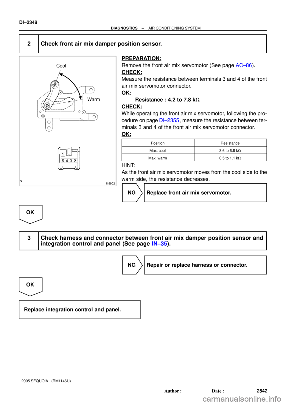
2 Check front air mix damper position sensor.
PREPARATION:
Remove the front air mix servomotor (See page AC±86).
CHECK:
Measure the resistance between terminals 3 and 4 of the front
air mix servomotor connector.
OK:
Resistance : 4.2 to 7.8 kW
CHECK:
While operating the front air mix servomotor, following the pro-
cedure on page DI±2355, measure the resistance between ter-
minals 3 and 4 of the front air mix servomotor connector.
OK:
PositionResistance
Max. cool3.6 to 6.8 kW
Max. warm0.5 to 1.1 kW
HINT:
As the front air mix servomotor moves from the cool side to the
warm side, the resistance decreases.
NG Replace front air mix servomotor.
OK
3 Check harness and connector between front air mix damper position sensor and
integration control and panel (See page IN±35).
NG Repair or replace harness or connector.
OK
Replace integration control and panel.
Page 2551 of 4323

4
1
0
100 %
TPI terminal voltage
Damper opening angle
I15866
A16
Air Inlet Control
Servomotor
1
Y±R 2 311
16
13S5±AI
TPI
SG±TPI Integration Control
and Panel
I20 L±B
W VZ
PT
GNDI20
I20
± DIAG")
(V)
4
1
0
100 %
TPI terminal voltage
Damper opening angle
I15866
A16
Air Inlet Control
Servomotor
1
Y±R 2 311
16
13S5±AI
TPI
SG±TPI Integration Control
and Panel
I20 L±B
W VZ
PT
GNDI20
I20
± DIAGNOSTICSAIR CONDITIONING SYSTEM
DI±2349
2543 Author�: Date�:
2005 SEQUOIA (RM1146U)
DTC 32 Air Inlet Damper Position Sensor Circuit
CIRCUIT DESCRIPTION
This sensor detects the position of the air inlet damper and
sends the appropriate signals to the integration control and
panel.
The position sensor is built into the air inlet damper control ser-
vomotor assembly.
DTC No.Detection ItemTrouble Area
32Short to ground or short to power source circuit in air inlet
�Air inlet damper position sensor
�Harness or connector between air inlet damper position sen-
32Short to ground or short to ower source circuit in air inlet
damper position sensor circuit.
�Harness or connector between air inlet dam er osition sen-
sor and integration control and panel
�Integration control and panel
WIRING DIAGRAM
DI3FG±10
Page 2553 of 4323
I25201
RECFRS
± DIAGNOSTICSAIR CONDITIONING SYSTEM
DI±2351
2545 Author�: Date�:
2005 SEQUOIA (RM1146U)
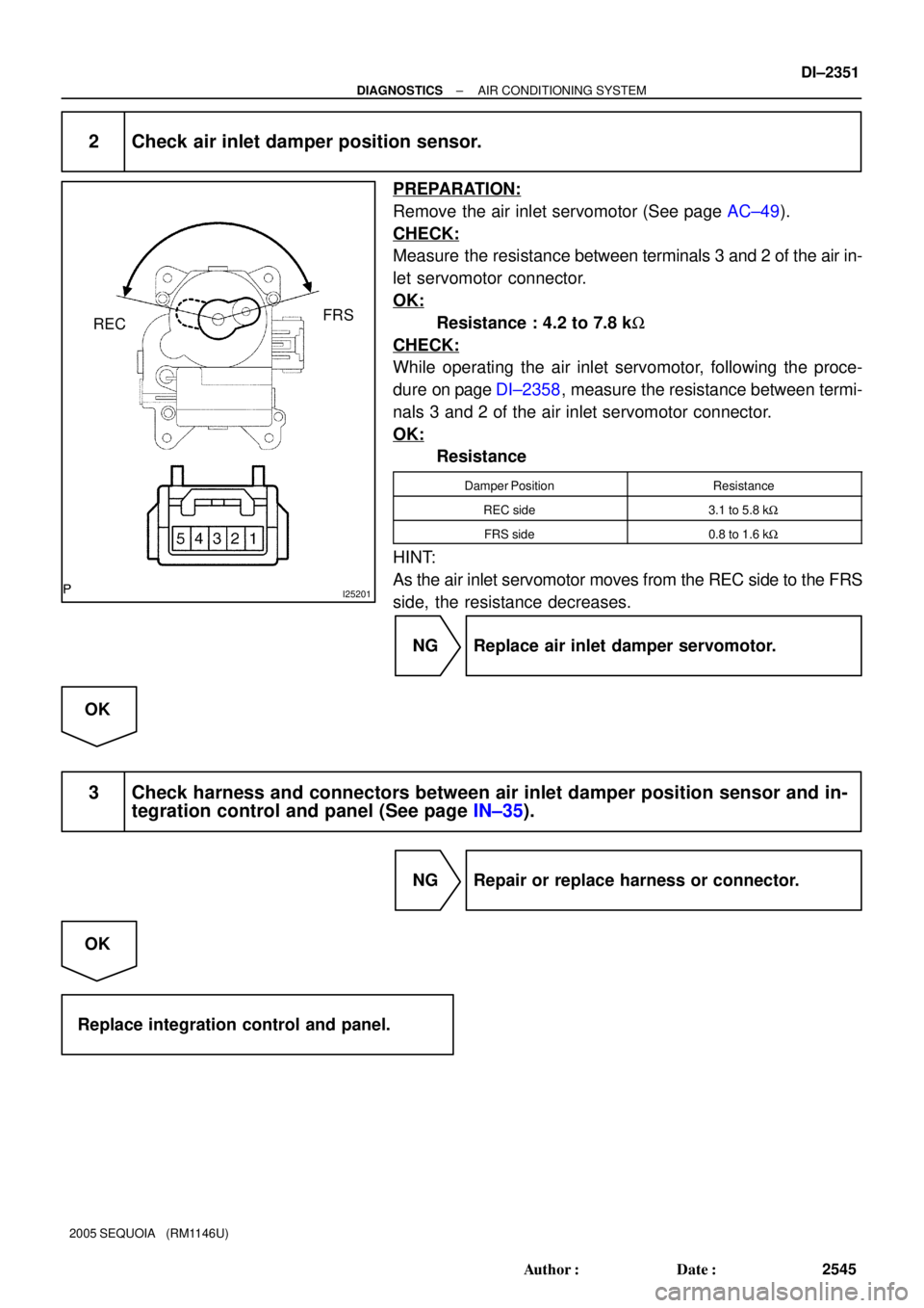
2 Check air inlet damper position sensor.
PREPARATION:
Remove the air inlet servomotor (See page AC±49).
CHECK:
Measure the resistance between terminals 3 and 2 of the air in-
let servomotor connector.
OK:
Resistance : 4.2 to 7.8 kW
CHECK:
While operating the air inlet servomotor, following the proce-
dure on page DI±2358, measure the resistance between termi-
nals 3 and 2 of the air inlet servomotor connector.
OK:
Resistance
Damper PositionResistance
REC side3.1 to 5.8 kW
FRS side0.8 to 1.6 kW
HINT:
As the air inlet servomotor moves from the REC side to the FRS
side, the resistance decreases.
NG Replace air inlet damper servomotor.
OK
3 Check harness and connectors between air inlet damper position sensor and in-
tegration control and panel (See page IN±35).
NG Repair or replace harness or connector.
OK
Replace integration control and panel.
Page 2554 of 4323

1
TP terminal voltage0 100 %
(Cool)
(Hot)
Damper opening angle
I28838
A34 A/C Water Valve (Rear)
3 2
1
W W
5L±Y1
10
18RrS5
RrSG
RrTP Integration Control
and Panel
I21
L±R L±Y
O IJ3 BH1
L±R 7")
4 (V)
1
TP terminal voltage0 100 %
(Cool)
(Hot)
Damper opening angle
I28838
A34 A/C Water Valve (Rear)
3 2
1
W W
5L±Y1
10
18RrS5
RrSG
RrTP Integration Control
and Panel
I21
L±R L±Y
O IJ3 BH1
L±R 7
L±Y
1
W
A L±R
IG
J/C
J438
6
(Shielded)
6 BH1
BH116 w/ Rear A/C:
(Shielded)
O
A VZ
GND
PTI21
I21 IJ3
IJ3
IJ3 DI±2352
± DIAGNOSTICSAIR CONDITIONING SYSTEM
2546 Author�: Date�:
2005 SEQUOIA (RM1146U)
DTC 37 Water Valve Damper Position Sensor Circuit
CIRCUIT DESCRIPTION
This sensor detects the position of the air mix damper and
sends the appropriate signals to the integration control and
panel.
The position sensor is built into the water valve damper control
servomotor assembly.
DTC No.Detection ItemTrouble Area
37Short to ground or short to power source circuit in water valve
�Water valve damper position sensor
�Harness or connector between water valve damper position
37Short to ground or short to ower source circuit in water valve
damper position sensor circuit.
�Harness or connector between water valve dam er osition
sensor and integration control and panel
�Integration control and panel
WIRING DIAGRAM
DI3FH±14

 Low pressure side High pressure side
OFF
(10 kW or higher)OFF
(10 kW or higher) (2.0 kgfVcm
2, 28 psi) (32.0 kgfVcm2, 455 psi) 196 KPa 3,140 KPa DI±2342
± DIAGNOSTICSAIR CO")