Page 1151 of 4323
± DIAGNOSTICSABS WITH EBD & BA & TRAC & VSC SYSTEM
DI±949
1143 Author�: Date�:
2005 SEQUOIA (RM1146U)
3 Check for open and short circuit in harness and connector between steering
angle sensor and translate ECU (See page IN±35).
NG Repair or replace harness or connector.
OK
4 Check for open and short circuit in harness and connector between skid control
ECU and translate ECU (CAN1 circuit).
NG Repair or replace harness or connector
(CAN1 circuit).
OK
5 Is DTC still output?
Check DTC on page DI±911.
NO No problem.
YES
Page 1155 of 4323
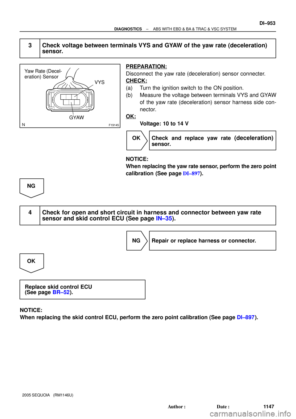
F19145
Yaw Rate (Decel-
eration) Sensor
VYS
GYAW
± DIAGNOSTICSABS WITH EBD & BA & TRAC & VSC SYSTEM
DI±953
1147 Author�: Date�:
2005 SEQUOIA (RM1146U)
3 Check voltage between terminals VYS and GYAW of the yaw rate (deceleration)
sensor.
PREPARATION:
Disconnect the yaw rate (deceleration) sensor connecter.
CHECK:
(a) Turn the ignition switch to the ON position.
(b) Measure the voltage between terminals VYS and GYAW
of the yaw rate (deceleration) sensor harness side con-
nector.
OK:
Voltage: 10 to 14 V
OK Check and replace yaw rate
(deceleration)
sensor.
NOTICE:
When replacing the yaw rate sensor, perform the zero point
calibration (See page DI±897).
NG
4 Check for open and short circuit in harness and connector between yaw rate
sensor and skid control ECU (See page IN±35).
NG Repair or replace harness or connector.
OK
Replace skid control ECU
(See page BR±52).
NOTICE:
When replacing the skid control ECU, perform the zero point calibration (See page DI±897).
Page 1158 of 4323
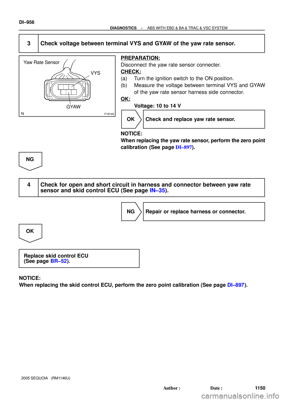
F19145
Yaw Rate Sensor
VYS
GYAW
DI±956
± DIAGNOSTICSABS WITH EBD & BA & TRAC & VSC SYSTEM
1150 Author�: Date�:
2005 SEQUOIA (RM1146U)
3 Check voltage between terminal VYS and GYAW of the yaw rate sensor.
PREPARATION:
Disconnect the yaw rate sensor connecter.
CHECK:
(a) Turn the ignition switch to the ON position.
(b) Measure the voltage between terminal VYS and GYAW
of the yaw rate sensor harness side connector.
OK:
Voltage: 10 to 14 V
OK Check and replace yaw rate sensor.
NOTICE:
When replacing the yaw rate sensor, perform the zero point
calibration (See page DI±897).
NG
4 Check for open and short circuit in harness and connector between yaw rate
sensor and skid control ECU (See page IN±35).
NG Repair or replace harness or connector.
OK
Replace skid control ECU
(See page BR±52).
NOTICE:
When replacing the skid control ECU, perform the zero point calibration (See page DI±897).
Page 1164 of 4323
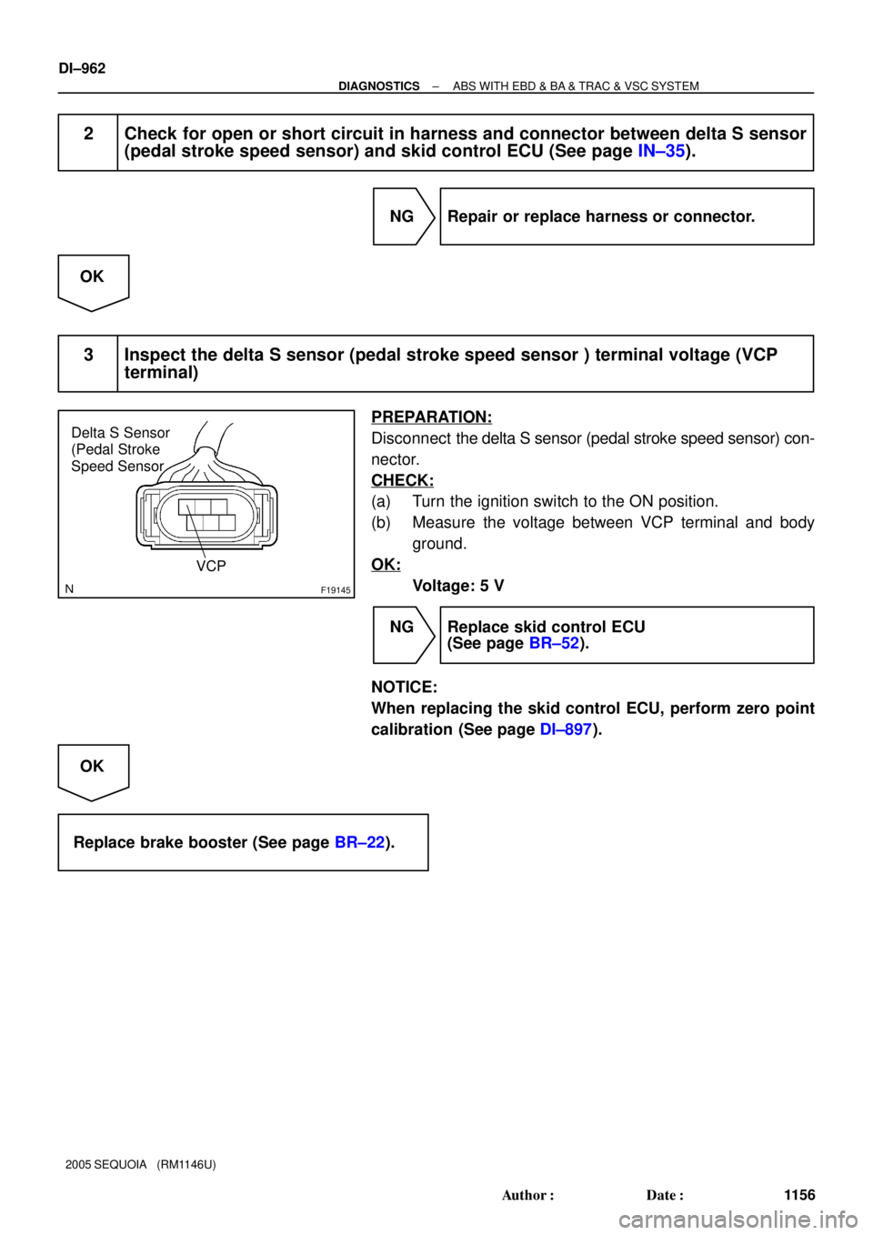
F19145
Delta S Sensor
(Pedal Stroke
Speed Sensor
VCP
DI±962
± DIAGNOSTICSABS WITH EBD & BA & TRAC & VSC SYSTEM
1156 Author�: Date�:
2005 SEQUOIA (RM1146U)
2 Check for open or short circuit in harness and connector between delta S sensor
(pedal stroke speed sensor) and skid control ECU (See page IN±35).
NG Repair or replace harness or connector.
OK
3 Inspect the delta S sensor (pedal stroke speed sensor ) terminal voltage (VCP
terminal)
PREPARATION:
Disconnect the delta S sensor (pedal stroke speed sensor) con-
nector.
CHECK:
(a) Turn the ignition switch to the ON position.
(b) Measure the voltage between VCP terminal and body
ground.
OK:
Voltage: 5 V
NG Replace skid control ECU
(See page BR±52).
NOTICE:
When replacing the skid control ECU, perform zero point
calibration (See page DI±897).
OK
Replace brake booster (See page BR±22).
Page 1178 of 4323
DI±976
± DIAGNOSTICSABS WITH EBD & BA & TRAC & VSC SYSTEM
1170 Author�: Date�:
2005 SEQUOIA (RM1146U)
4 Check harness and connector between speed sensor and skid control ECU
(See page IN±35).
NG Repair or replace harness or connector.
OK
Replace skid control ECU
(See page BR±52).
NOTICE:
When replacing the skid control ECU, perform the zero point calibration (See page DI±897).
Page 1186 of 4323

INSPECTION PROCEDURE
1 Is pedal lowered or spongy?
YES Bleed air from the system (See page BR�")
DI±984
± DIAGNOSTICSABS WITH EBD & BA & TRAC & VSC SYSTEM
1178 Author�: Date�:
2005 SEQUOIA (RM1146U)
INSPECTION PROCEDURE
1 Is pedal lowered or spongy?
YES Bleed air from the system (See page BR±4).
NO
2 Check output value of the master cylinder pressure sensor No. 1 and No. 2.
PREPARATION:
(a) Connect the hand±held tester to the DLC3.
(b) Turn the ignition switch to the ON position, and push the hand±held tester main switch ON.
(c) Select DATA LIST mode on the hand±held tester.
CHECK:
Check that the brake fluid pressure value of the master cylinder pressure sensor displayed on the hand±held
tester changes when depressing the brake pedal.
ItemMeasurement Item /
Range (Display)Normal ConditionDiagnostic Note
MAS CYL PRS 1
Master cylinder pressure
sensor 1 reading / min.: 0
V, max.: 5 VWhen brake pedal is re-
leased : 0.3 to 0.9 VReading increases when
brake pedal is depressed
MAS CYL PRS 2
Master cylinder pressure
sensor 1 reading / min.: 0
V, max.: 5 VWhen brake pedal is re-
leased : 0.3 to 0.9 VReading increases when
brake pedal is depressed
OK:
Brake fluid pressure value changes.
OK Go to step 4.
NG
3 Check for open and short circuit in harness and connector between master cyl-
inder pressure sensor and skid control ECU (See page IN±35).
NG Repair or replace harness or connector.
OK
Page 1190 of 4323
F19146
Master Cylinder
Pressure Sensor
No. 1Master Cylinder
Pressure Sensor
No. 2
VCM E1VCM2
E2
M3 M2
DI±988
± DIAGNOSTICSABS WITH EBD & BA & TRAC & VSC SYSTEM
1182 Author�: Date�:
2005 SEQUOIA (RM1146U)
INSPECTION PROCEDURE
1 Check battery positive voltage.
OK:
Voltage: 10 to 14 V
NG Check and repair the charging system
(See page CH±1).
OK
2 Check master cylinder pressure sensor No. 1 and No. 2.
PREPARATION:
Disconnect the master cylinder pressure sensor connectors
No. 1 and No. 2.
CHECK:
(1) Turn the ignition switch to the ON position.
(2) Measure the voltage between terminal VCM and
E1, VCM2 and E2 of the harness side connector.
OK:
Voltage: 4.5 to 5.5 V
NG Go to step 4.
OK
Page 1191 of 4323
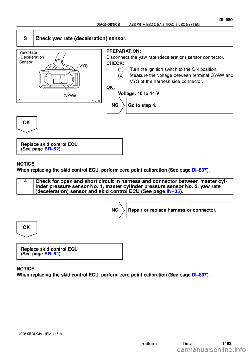
F19145
Yaw Rate
(Deceleration)
Sensor
VYS
GYAW
± DIAGNOSTICSABS WITH EBD & BA & TRAC & VSC SYSTEM
DI±989
1183 Author�: Date�:
2005 SEQUOIA (RM1146U)
3 Check yaw rate (deceleration) sensor.
PREPARATION:
Disconnect the yaw rate (deceleration) sensor connector.
CHECK:
(1) Turn the ignition switch to the ON position.
(2) Measure the voltage between terminal GYAW and
VYS of the harness side connector.
OK:
Voltage: 10 to 14 V
NG Go to step 4.
OK
Replace skid control ECU
(See page BR±52).
NOTICE:
When replacing the skid control ECU, perform zero point calibration (See page DI±897).
4 Check for open and short circuit in harness and connector between master cyl-
inder pressure sensor No. 1, master cylinder pressure sensor No. 2, yaw rate
(deceleration) sensor and skid control ECU (See page IN±35).
NG Repair or replace harness or connector.
OK
Replace skid control ECU
(See page BR±52).
NOTICE:
When replacing the skid control ECU, perform zero point calibration (See page DI±897).