Page 472 of 4323
B17417
E4
PPMP
A23446
L5
DI±270
± DIAGNOSTICSENGINE
464 Author�: Date�:
2005 SEQUOIA (RM1146U)
3 Measure resistance between terminal PPMP of ECM and body ground.
PREPARATION:
(a) Disconnect the L5 canister connector.
(b) Disconnect the E4 ECM connector.
CHECK:
Check the resistance between PPMP terminal of the ECM con-
nector and the body ground.
Result:
Test ResultsSuspected Trouble AreasProceed To
10 kW or more�Short in pressure sensor circuitA
10 W or less�Short in wire harness/connector (ECM ± pressure sensor)B
A Go to step 5.
B Go to step 6.
Page 473 of 4323

A23508
Wire Harness Side:
Canister Connector
Front View
L5
A23446
L5
± DIAGNOSTICSENGINE
DI±271
465 Author�: Date�:
2005 SEQUOIA (RM1146U)
4 Measure voltage and resistance of pump module connector.
PREPARATION:
(a) Disconnect the L5 canister connector.
(b) Turn the ignition switch to ON.
CHECK:
Measure the voltage and resistance of the L5 connector.
OK:
Standard:
Tester ConnectionsSpecified Conditions
L5±4 ± Body groundBetween 4.5 V and 5.5 V
L5±3 ± Body groundBetween 4.5 V and 5.5 V
L5±2 ± Body ground100 W or less
RESULT:
Test ResultsSuspected Trouble AreasProceed To
Voltage and resistance within standard ranges�Open in pressure sensor circuitA
Voltage and resistance outside standard ranges�Open in wire harness/connector (ECM ± pressure sensor)B
B Go to step 6.
A
5 Replace charcoal canister assembly.
NEXT Go to step 8.
6 Repair or replace wire harness and connectors.
HINT:
If the exhaust tail pipe has been removed, go to the next step before reinstalling it.
NEXT Go to step 8.
Page 484 of 4323
BR3795OK NGClearance
B17411
SPD(+) E5
A23540
Wire Harness Side:
Front View
Combination Meter Connector C5
DI±282
± DIAGNOSTICSENGINE
476 Author�: Date�:
2005 SEQUOIA (RM1146U)
4 Check sensor installation (Vehicle speed sensor).
CHECK:
Check the vehicle speed sensor installation.
OK:
The vehicle speed sensor is installed properly.
NG Tighten sensor installation bolt.
OK
5 Check for open and short in harness and connector between combination meter
and ECM.
PREPARATION:
(a) Disconnect the C5 combination meter connector.
(b) Disconnect the E5 ECM connector.
CHECK:
Check for resistance between the wire harness side connec-
tors.
OK:
Standard (Check for open):
Symbols (Terminal No.)Specified condition
SPD (E5±8) ± C5±25Below 1 W
Standard (Check for short):
Symbols (Terminal No.)Specified condition
SPD (E5±8) or C5±25 ± Body ground10 kW or higher
NG Repair or replace harness or connector.
OK
Check combination meter circuit (See page
DI±1632
Page 508 of 4323

B17445
Wire Harness Side:
Camshaft Position Sensor
A23559
2 V / DIV
GND
Crank Angle
120°120° 180°
180°
60°60°
200 ms /DIV
B17414
E6ECM Connector
G2+
G2±
DI±306
± DIAGNOSTICSENGINE
500 Author�: Date�:
2005 SEQUOIA (RM1146U)
INSPECTION PROCEDURE
HINT:
Read freeze frame data using hand±held tester. Because freeze frame records the engine conditions when
the malfunction is detected. When troubleshooting, it is useful for determining whether the vehicle was run-
ning or stopped, the engine was warmed up or not, the air±fuel ratio was lean or rich, etc. at the time of the
malfunction.
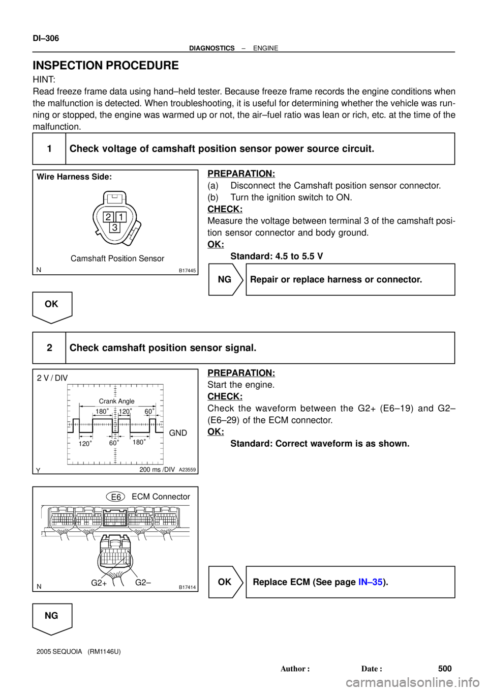
1 Check voltage of camshaft position sensor power source circuit.
PREPARATION:
(a) Disconnect the Camshaft position sensor connector.
(b) Turn the ignition switch to ON.
CHECK:
Measure the voltage between terminal 3 of the camshaft posi-
tion sensor connector and body ground.
OK:
Standard: 4.5 to 5.5 V
NG Repair or replace harness or connector.
OK
2 Check camshaft position sensor signal.
PREPARATION:
Start the engine.
CHECK:
Check the waveform between the G2+ (E6±19) and G2±
(E6±29) of the ECM connector.
OK:
Standard: Correct waveform is as shown.
OK Replace ECM (See page IN±35).
NG
Page 509 of 4323

B17414
E6ECM Connector
G2+
G2±
B17445
Wire Harness Side:
Camshaft Position Sensor C1
BR3795OK NGClearance
± DIAGNOSTICSENGINE
DI±307
501 Author�: Date�:
2005 SEQUOIA (RM1146U)
3 Check for open and short in harness and connector between ECM and camshaft
position sensor.
PREPARATION:
(a) Disconnect the Camshaft position sensor connector.
(b) Disconnect the E6 ECM connector.
CHECK:
Measure the resistance between wire harness side connectors.
OK:
Standard:
Tester ConnectionSpecified Condition
Camshaft position sensor (C1±2) ±
G2+ (E6±19)Below 1 W
Camshaft position sensor (C1±1) ±
G2± (E6±29)Below 1 W
Camshaft position sensor (C1±2) or
G2+ (E6±19) ± Body ground10 kW or higher
Camshaft position sensor (C1±1) or
G2± (E6±29) ± Body ground10 kW or higher
NG Repair or replace harness or connector.
OK
4 Inspect sensor installation and signal plate tooth of LH camshaft timing pulley.
CHECK:
Check the camshaft position sensor installation.
OK:
The camshaft position sensor is installed properly.
NG Tighten sensor installation bolt.
OK
Page 559 of 4323

A21022
T14
M+ M±
Wire Harness Side:
Throttle Control Motor and Sensor
B17412M+
M±
E8ECM Connector
± DIAGNOSTICSENGINE
DI±357
551 Author�: Date�:
2005 SEQUOIA (RM1146U)
2 Check for open and short in harness and connector between throttle control mo-
tor and ECM.
PREPARATION:
(a) Disconnect the T14 throttle control motor and sensor con-
nector.
(b) Disconnect the E8 ECM connector.
CHECK:
Measure the resistance between the wire harness side connec-
tors.
OK:
Standard:
Tester ConnectionSpecified Condition
M+ (T14±2) ± M+ (E8±3)Below 1 W
M± (T14±1) ± M± (E8±2)Below 1 W
M+ (T14±2) or M+ (E8±3) ±
Body ground10 kW or higher
M± (T14±1) or M± (E8±2) ±
Body ground10 kW or higher
NG Repair or replace harness or connector.
OK
3 Visually check throttle valve.
CHECK:
Check the area between the throttle valve and the housing for foreign objects.
Also, check if the valve can open and close smoothly.
OK:
The throttle valve is not contaminated by foreign objects and can move smoothly.
NG Remove foreign object and clean throttle body.
OK
Replace ECM (See page SF±80).
Page 563 of 4323

A21034
T14
Component Side:
M+M± Throttle Control Motor and Sensor
A21022
T14
M+ M±
Wire Harness Side:
Throttle Control Motor and Sensor
B17412M+
M±
E8ECM Connector
± DIAGNOSTICSENGINE
DI±361
555 Author�: Date�:
2005 SEQUOIA (RM1146U)
3 Check throttle control motor.
PREPARATION:
Disconnect the throttle control motor and sensor connector.
CHECK:
Measure the resistance between terminals of the throttle con-
trol motor.
OK:
Standard:
Tester ConnectionSpecified Condition
M+ (T14±2) ± M± (T14±1)0.3 to100 W (20°C (68°F))
NG Replace throttle body (See page SF±39).
OK
4 Check for open and short in harness and connector between ECM and throttle
control motor.
PREPARATION:
(a) Disconnect the T14 throttle control motor and sensor con-
nector.
(b) Disconnect the E8 ECM connector.
CHECK:
Measure the resistance between the wire harness side connec-
tors.
OK:
Standard:
Tester ConnectionSpecified Condition
M+ (T14±2) ± M+ (E8±3)Below 1 W
M± (T14±1) ± M± (E8±2)Below 1 W
M+ (T14±2) or M+ (E8±3) ±
Body ground10 kW or higher
M± (T14±1) or M± (E8±2) ±
Body ground10 kW or higher
NG Repair or replace harness or connector.
OK
Check for intermittent problems
(See page DI±11).
Page 579 of 4323

A21022
Wire Harness Side:
A37
Accelerator Pedal Position Sensor
VCP2
EPA2
VPA2
VCPAEPAVPA
B17417
E4VPA2
VCPAVPA
EPA2
EPAVCP2
± DIAGNOSTICSENGINE
DI±377
571 Author�: Date�:
2005 SEQUOIA (RM1146U)
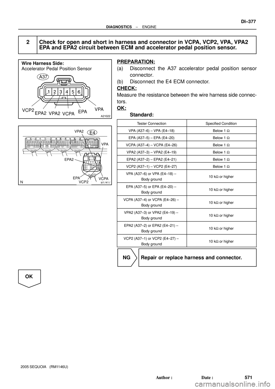
2 Check for open and short in harness and connector in VCPA, VCP2, VPA, VPA2
EPA and EPA2 circuit between ECM and accelerator pedal position sensor.
PREPARATION:
(a) Disconnect the A37 accelerator pedal position sensor
connector.
(b) Disconnect the E4 ECM connector.
CHECK:
Measure the resistance between the wire harness side connec-
tors.
OK:
Standard:
Tester ConnectionSpecified Condition
VPA (A37±6) ± VPA (E4±18)Below 1 W
EPA (A37±5) ± EPA (E4±20)Below 1 W
VCPA (A37±4) ± VCPA (E4±26)Below 1 W
VPA2 (A37±3) ± VPA2 (E4±19)Below 1 W
EPA2 (A37±2) ± EPA2 (E4±21)Below 1 W
VCP2 (A37±1) ± VCP2 (E4±27)Below 1 W
VPA (A37±6) or VPA (E4±18) ±
Body ground10 kW or higher
EPA (A37±5) or EPA (E4±20) ±
Body ground10 kW or higher
VCPA (A37±4) or VCPA (E4±26) ±
Body ground10 kW or higher
VPA2 (A37±3) or VPA2 (E4±19) ±
Body ground10 kW or higher
EPA2 (A37±2) or EPA2 (E4±21) ±
Body ground10 kW or higher
VCP2 (A37±1) or VCP2 (E4±27) ±
Body ground10 kW or higher
NG Repair or replace harness and connector.
OK