Page 311 of 4323

A19549
THA
E2ECM
2
1
Mass Air
Flow Meter Mass Air
Flow Meter
45
M1
THA E2
M1
B17441THA
E2
THA
E2ECM Mass Air Flow Meter
M1
E8
± DIAGNOSTICSENGINE
DI±117
311 Author�: Date�:
2005 SEQUOIA (RM1146U)
2 Check for open in harness or ECM.
PREPARATION:
(a) Disconnect the M1 mass air flow meter connector.
(b) Connect terminals 4 and 5 of the mass air flow meter wire
harness side connector.
(c) Turn the ignition switch ON.
(d) When using hand±held tester, enter the following menu:
DIAGNOSIS / ENHANCED OBD II / DATA LIST / ALL / IN-
TAKE AIR.
CHECK:
Read the temperature value on the hand±held tester.
OK:
Standard: Temperature value: 1405C (2845F) or more
OK Confirm good connection at sensor. If OK, re-
place mass air flow meter.
NG
3 Check for open in harness or ECM.
PREPARATION:
(a) Connect terminals THA and E2 of the E8 ECM connector.
HINT:
Before checking, do a visual and contact pressure check for the
ECM connector.
(b) Turn the ignition switch ON.
(c) When using hand±held tester, enter the following menu:
DIAGNOSIS / ENHANCED OBD II / DATA LIST / ALL / IN-
TAKE AIR.
CHECK:
Read the temperature value on the hand±held tester.
OK:
Standard: Temperature value: 1405C (2845F) or more
OK Repair or replace harness or connector.
NG
Confirm good connection at ECM. If OK, re-
place ECM (See page SF±80).
Page 317 of 4323

A19552
Engine Coolant
Temp. Sensor
2
1THW
E2ECM
E2
B17441
Engine Coolant
Temp. Sensor
ECM
E2 THW
E2
THW
E2
E8ECM Connector
± DIAGNOSTICSENGINE
DI±123
317 Author�: Date�:
2005 SEQUOIA (RM1146U)
2 Check for open in harness or ECM.
PREPARATION:
(a) Disconnect the E2 engine coolant temperature (ECT)
sensor connector.
(b) Connect terminals 1 and 2 of the engine coolant tempera-
ture sensor wire harness side connector.
(c) Turn the ignition switch ON.
(d) When using hand±held tester, enter the following menu:
DIAGNOSIS / ENHANCED OBD II / DATA LIST / ALL /
COOLANT TEMP.
CHECK:
Read the temperature value on the hand±held tester.
OK:
Standard: Temperature value: 1405C (2845F) or more
OK Confirm good connection at sensor. If OK, re-
place engine coolant temperature sensor.
NG
3 Check for open in harness or ECM.
PREPARATION:
(a) Disconnect the E2 engine coolant temperature sensor
connector.
(b) Connect terminals THW and E2 of the E8 ECM connector.
HINT:
Before checking, do a visual and contact pressure checks for
the ECM connector.
(c) Turn the ignition switch ON.
(d) When using hand±held tester, enter the following menu:
DIAGNOSIS / ENHANCED OBD II / DATA LIST / ALL /
COOLANT TEMP.
CHECK:
Read the temperature value on the OBD II scan tool or the
hand±held tester.
OK:
Standard: Temperature value: 1405C (2845F) or more
OK Repair or replace harness or connector.
NG
Page 318 of 4323

A19550
Engine Coolant
Temp. Sensor
ECM
2
1
E2 THW E2
B17442
ECM Engine Coolant
Temp. Sensor
E2 THW E2
ECM Connector E8
DI±124
± DIAGNOSTICSENGINE
318 Author�: Date�:
2005 SEQUOIA (RM1146U)
Confirm good connection at ECM. If OK, re-
place ECM (See page SF±80).
4 Check for short in harness and ECM.
PREPARATION:
(a) Disconnect the E2 engine coolant temperature sensor
connector.
(b) Turn the ignition switch ON.
(c) When using hand±held tester, enter the following menu:
DIAGNOSIS / ENHANCED OBD II / DATA LIST / ALL /
COOLANT TEMP.
CHECK:
Read the temperature value on the hand±held tester.
OK:
Standard: Temperature value: ±405C (±405F)
OK Replace engine coolant temperature sensor.
NG
5 Check for short in harness or ECM.
PREPARATION:
(a) Disconnect the E8 ECM connector.
(b) Turn the ignition switch ON.
(c) When using hand±held tester, enter the following menu:
DIAGNOSIS / ENHANCED OBD II / DATA LIST / ALL /
COOLANT TEMP.
CHECK:
Read the temperature value on the hand±held tester.
OK:
Standard: Temperature value: ±405C (±405F)
OK Repair or replace harness or connector.
NG
Replace ECM (See page SF±80).
Page 328 of 4323
A21022
Throttle Control Motor and Sensor
VC VTA2VTA1
E2 Wire Harness Side
T14
Front View
B17412VC
E2
E8ECM Connector
VTA2
VTA1
DI±134
± DIAGNOSTICSENGINE
328 Author�: Date�:
2005 SEQUOIA (RM1146U)
2 Check for open and short in harness and connector between ECM and throttle
position sensor.
PREPARATION:
(a) Disconnect the T14 throttle control motor and sensor con-
nector.
(b) Disconnect the E8 ECM connector.
CHECK:
Check the resistance between the wire harness side connec-
tors.
OK:
Standard:
Tester ConnectionSpecified Condition
VC (T14±5) ± VC (E8±18)Below 1 W
VTA1 (T14±6) ± VTA1 (E8±21)Below 1 W
VTA2 (T14±4) ± VTA2 (E8±31)Below 1 W
E2 (T14±3) ± E2 (E8±28)Below 1 W
VC (T14±5) or VC (E8±18) ±
Body ground10 kW or higher
VTA1 (T14±6) or VTA1 (E8±21) ±
Body ground10 kW or higher
VTA2 (T14±4) or VTA2 (E8±31) ±
Body ground10 kW or higher
NG Repair or replace harness or connector.
OK
Page 352 of 4323

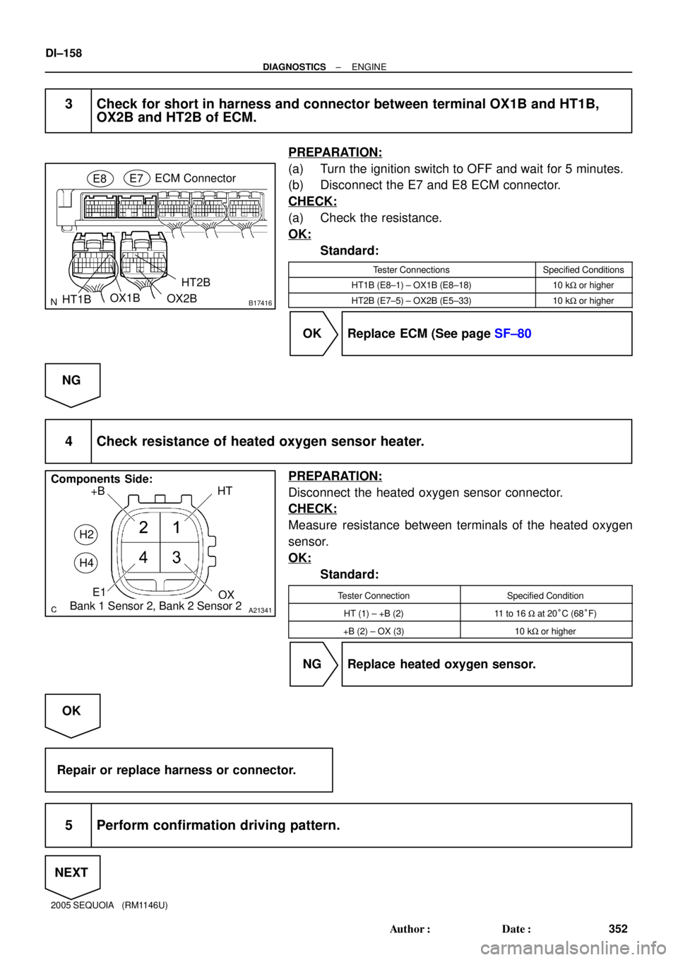
B17416HT1BECM Connector
E7OX1B E8
HT2B
OX2B
A21341
+B
OX E1HT
H2
H4
Components Side:
Bank 1 Sensor 2, Bank 2 Sensor 2
DI±158
± DIAGNOSTICSENGINE
352 Author�: Date�:
2005 SEQUOIA (RM1146U)
3 Check for short in harness and connector between terminal OX1B and HT1B,
OX2B and HT2B of ECM.
PREPARATION:
(a) Turn the ignition switch to OFF and wait for 5 minutes.
(b) Disconnect the E7 and E8 ECM connector.
CHECK:
(a) Check the resistance.
OK:
Standard:
Tester ConnectionsSpecified Conditions
HT1B (E8±1) ± OX1B (E8±18)10 kW or higher
HT2B (E7±5) ± OX2B (E5±33)10 kW or higher
OK Replace ECM (See page SF±80
NG
4 Check resistance of heated oxygen sensor heater.
PREPARATION:
Disconnect the heated oxygen sensor connector.
CHECK:
Measure resistance between terminals of the heated oxygen
sensor.
OK:
Standard:
Tester ConnectionSpecified Condition
HT (1) ± +B (2)11 to 16 W at 20°C (68°F)
+B (2) ± OX (3)10 kW or higher
NG Replace heated oxygen sensor.
OK
Repair or replace harness or connector.
5 Perform confirmation driving pattern.
NEXT
Page 358 of 4323

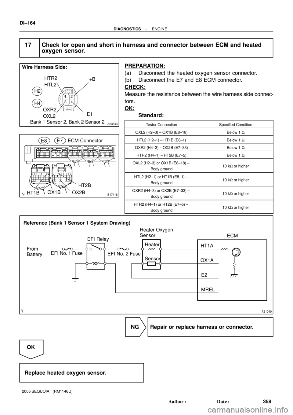
A23543
+B
OXR2
OXL2E1 HTR2
HTL2
H2
H4
Wire Harness Side:
Bank 1 Sensor 2, Bank 2 Sensor 2
B17416HT1BECM Connector E7OX1B E8
HT2B
OX2B
A21040
Reference (Bank 1 Sensor 1 System Drawing)
From
BatteryEFI No. 1 FuseEFI Relay
EFI No. 2 FuseHeater Oxygen
Sensor
Heater
SensorHT1A
OX1A
E2
MRELECM
DI±164
± DIAGNOSTICSENGINE
358 Author�: Date�:
2005 SEQUOIA (RM1146U)
17 Check for open and short in harness and connector between ECM and heated
oxygen sensor.
PREPARATION:
(a) Disconnect the heated oxygen sensor connector.
(b) Disconnect the E7 and E8 ECM connector.
CHECK:
Measure the resistance between the wire harness side connec-
tors.
OK:
Standard:
Tester ConnectionSpecified Condition
OXL2 (H2±3) ± OX1B (E8±18)Below 1 W
HTL2 (H2±1) ± HT1B (E8±1)Below 1 W
OXR2 (H4±3) ± OX2B (E7±33)Below 1 W
HTR2 (H4±1) ± HT2B (E7±5)Below 1 W
OXL2 (H2±3) or OX1B (E8±18) ±
Body ground10 kW or higher
HTL2 (H2±1) or HT1B (E8±1) ±
Body ground10 kW or higher
OXR2 (H4±3) or OX2B (E7±33) ±
Body ground10 kW or higher
HTR2 (H4±1) or HT2B (E7±5) ±
Body ground10 kW or higher
NG Repair or replace harness or connector.
OK
Replace heated oxygen sensor.
Page 369 of 4323

A19288
A/F Relay
A23659
Wire Harness Side:
HT
A38
Sensor 1A/F Sensor Connector
AF+
Front ViewAF±
+B A39
B17415
E7ECM Connector
HA1A
A1A+
A1A±
A2A+
A2A±HA2A
± DIAGNOSTICSENGINE
DI±175
369 Author�: Date�:
2005 SEQUOIA (RM1146U)
12 Check A/F relay.
PREPARATION:
Remove the A/F relay from the engine room J/B.
CHECK:
Inspect the A/F relay.
OK:
Standard:
Terminal No.ConditionSpecified Condition
3 ± 5Always10 KW or higher
3 ± 5Apply B+ between
terminals 1 and 2Below 1 W
NG Replace A/F relay.
OK
13 Check for open and short in harness and connector between ECM and A/F sen-
sor.
PREPARATION:
(a) Disconnect the A38 or A39 A/F sensor connector.
(b) Turn the ignition switch to ON.
CHECK:
(a) Measure the voltage between the +B terminal of the A/F
sensor connector and body ground.
OK:
Standard:
Tester ConnectionsSpecified Conditions
+B (2) ± Body ground9 to 14 V
PREPARATION:
(a) Turn the ignition switch to OFF.
(b) Disconnect the E7 ECM connector.
CHECK:
(a) Check the resistance.
OK:
Standard (Check for open):
Tester ConnectionsSpecified Conditions
HT (A38±1) ± HA1A (E7±2)
HT (A39±1) ± HA2A (E7±1)Below 1 W
AF+ (A38±3) ± A1A+ (E7±22)
AF+ (A39±3) ± A2A+ (E7±23)Below 1 W
AF± (A38±4) ± A1A± (E7±30)
AF± (A39±4) ± A2A± (E7±31)Below 1 W
Page 370 of 4323
A23512
Reference (Bank 1 Sensor 1 System Drawing):
A/F Sensor A/F Relay
Heater
Sensor
A1A+ HA1A
Duty
Control ECM
From
Battery
A/F Heater
Fuse
A1A±
To EFI Relay
DI±176
± DIAGNOSTICSENGINE
370 Author�: Date�:
2005 SEQUOIA (RM1146U)
Standard (Check for short):
Tester ConnectionsSpecified Conditions
HT (A38±1) or HA1A (E7±2) ± Body ground
HT (A39±1) or HA2A (E7±1) ± Body ground10 kW or higher
AF+ (A38±3) or A1A+ (E7±22) ± Body ground
AF+ (A39±3) or A2A+ (E7±23) ± Body ground10 kW or higher
AF± (A38±4) or A1A± (E7±30) ± Body ground
AF± (A39±4) or A2A± (E7±31) ± Body ground10 kW or higher
NG Replace or replace harness or connector.
OK
14 Replace air fuel ratio sensor.
NEXT