Page 801 of 4323
:
21 V2
D14166
ECM:
SP2+ SP2±E8E7E6E5E4
± DIAGNOSTICSAUTOMATIC TRANSMISSION
DI±599
793 Author�: Date�:
2005 SEQUOIA (RM1146U)
2 Inspect speed sensor SP2.")
D14165
Sensor Side:
(Connector Front View):
21 V2
D14166
ECM:
SP2+ SP2±E8E7E6E5E4
± DIAGNOSTICSAUTOMATIC TRANSMISSION
DI±599
793 Author�: Date�:
2005 SEQUOIA (RM1146U)
2 Inspect speed sensor SP2.
PREPARATION:
Disconnect the speed sensor connector from the transmission.
CHECK:
Measure the resistance according to the value(s) in the table
below.
OK:
Tester ConnectionSpecified Condition
20 �C (68 �F)
1 ± 2560 to 680 W
NG Replace speed sensor SP2 (See page AT±5).
OK
3 Check harness and connector (ECM ± speed sensor SP2).
PREPARATION:
(a) Connect the speed sensor connector.
(b) Disconnect the ECM connector.
CHECK:
Measure the resistance according to the value(s) in the table
below.
OK:
Tester ConnectionSpecified Condition
20�C (68�F)
E7 ± 34 (SP2+) ± E7 ± 26 (SP2±)560 to 680 W
CHECK:
Measure the resistance according to the value(s) in the table
below.
OK:
Tester ConnectionSpecified Condition
E7 ± 34 (SP2+) ± Body ground10 kW or higher
E7 ± 26 (SP2±) ± Body ground=
NG Repair or replace the harness or connector
(See page IN±35).
OK
Replace the ECM (See page SF±80).
Page 935 of 4323

F19456
Wire Harness Connector
Front View:
H15
SHB
SHG
F16805
S25
Suspension Control ECU
Wire Harness View:
SGL
SBL
F19456
Height Control Sensor Sub±assy
Connector Front View:
SHG H15
SHB
± DIAGNOSTICSAIR SUSPENSION SYSTEM
DI±733
927 Author�: Date�:
2005 SEQUOIA (RM1146U)
2 Check harness and connector (Height control sensor sub±assy power source).
PREPARATION:
(a) Disconnect the height control sensor sub±assy connec-
tor.
(b) Turn the ignition switch ON.
CHECK:
Measure the voltage between terminals 1 (SHB) and 3 (SHG)
of the height control sensor sub±assy wire harness side con-
nector.
OK:
Voltage: 4.5 to 5.5 V
OK Go to step 4.
NG
3 Check harness and connector (Height control sensor sub±assy ± Suspension
control ECU).
PREPARATION:
Disconnect the ECU connector.
CHECK:
(a) Check for an open or short circuit in the harness and the
connector between terminal 1 (SHB) of the height control
sensor sub±assy and S25±15 (SBL) of the suspension
control ECU.
(b) Check for an open or short circuit in the harness and the
connector between terminal 3 (SHG) of the height control
sensor sub±assy and S25±19 (SGL) of the suspension
control ECU.
OK:
There is no open or short circuit in the wire harness.
Page 936 of 4323
F16805
S25
Suspension Control ECU
Wire Harness View:
SHRL
F19456
Height Control Sensor Sub±assy
Connector Front View:
H15
SHRL
DI±734
± DIAGNOSTICSAIR SUSPENSION SYSTEM
928 Author�: Date�:
2005 SEQUOIA (RM1146U)
NG Repair or replace harness or connector.
OK
4 Check harness and connector (Height control sensor sub±assy ± Suspension
control ECU.
CHECK:
Check for an open or short circuit in the harness and the con-
nector between terminal 2 (SHRL) of the height control sensor
sub±assy and S25±17 (SHRL) of the suspension control ECU.
OK:
There is no open or short in the wire harness.
NG Repair or replace harness or connector.
OK
Page 1015 of 4323

DTC of SIGNAL CHECK (TEST DIAGNOSIS) function:
If a malfunction code is displayed during the test mode")
± DIAGNOSTICSTIRE PRESSURE WARNING SYSTEM
DI±813
1007 Author�: Date�:
2005 SEQUOIA (RM1146U)
DTC of SIGNAL CHECK (TEST DIAGNOSIS) function:
If a malfunction code is displayed during the test mode DTC check, check the circuit listed for that code. For
details of each code, refer to the ºSee Pageº under respective ºDTC No.º in the chart.
DTC No.
(See Page)Detection ItemTrouble Area
C2181/81
(DI±834)Transmitter ID1 not received
�Tire pressure monitor receiver assy
�Each tire pressure monitor valve sub±assy
�Tire pressure monitor ECU
�Wire harness
C2182/82
(DI±834)Transmitter ID2 not received
�Tire pressure monitor receiver assy
�Each tire pressure monitor valve sub±assy
�Tire pressure monitor ECU
�Wire harness
C2183/83
(DI±834)Transmitter ID3 not received
�Tire pressure monitor receiver assy
�Each tire pressure monitor valve sub±assy
�Tire pressure monitor ECU
�Wire harness
C2184/84
(DI±834)Transmitter ID4 not received
�Tire pressure monitor receiver assy
�Each tire pressure monitor valve sub±assy
�Tire pressure monitor ECU
�Wire harness
C2185/85
(DI±834)Transmitter ID5 not received
�Tire pressure monitor receiver assy
�Each tire pressure monitor valve sub±assy
�Tire pressure monitor ECU
�Wire harness
C2191/91
(DI±870)Vehicle speed signal error
�Vehicle speed sensor
�Combination meter assy
�Tire pressure monitor ECU
�Wire harness
Page 1028 of 4323
C2165/65
(DI±847)
Abnormal temperature inside ID1 tire
�Tire pressure monitor valve sub±assy
�Tire pre")
DI±826
± DIAGNOSTICSTIRE PRESSURE WARNING SYSTEM
1020 Author�: Date�:
2005 SEQUOIA (RM1146U)C2165/65
(DI±847)
Abnormal temperature inside ID1 tire
�Tire pressure monitor valve sub±assy
�Tire pressure monitor ECU
�Tire pressure monitor receiver assy
C2166/66
(DI±847)Abnormal temperature inside ID2 tire
�Tire pressure monitor valve sub±assy
�Tire pressure monitor ECU
�Tire pressure monitor receiver assy
C2167/67
(DI±847)Abnormal temperature inside ID3 tire
�Tire pressure monitor valve sub±assy
�Tire pressure monitor ECU
�Tire pressure monitor receiver assy
C2168/68
(DI±847)Abnormal temperature inside ID4 tire
�Tire pressure monitor valve sub±assy
�Tire pressure monitor ECU
�Tire pressure monitor receiver assy
C2169/69
(DI±847)Abnormal temperature inside ID5 tire
�Tire pressure monitor valve sub±assy
�Tire pressure monitor ECU
�Tire pressure monitor receiver assy
C2171/71
(DI±852)Transmitter ID not registeredTire pressure monitor ECU
C2176/76
(DI±854)Receiver error
�Tire pressure monitor receiver assy
�Tire pressure monitor ECU
�Wire harness
C2177/77
(DI±860)Initialization incomplete
�Tire pressure monitor valve sub±assy
�Tire pressure monitor ECU
�Tire pressure monitor receiver assy
�Wire harness
C2191/91
(DI±870)Vehicle speed signal error
�Vehicle speed sensor
�Tire pressure monitor ECU
�Combination meter
�Wire harness
Page 1072 of 4323
F19792
Combination Meter
Tire Pressure Monitor ECU
To BatterySPD G±O3
T17 C520
IEInstrument Panel J/BG±O
J8
J/C
AIF 10
1
1H11
T17GND
IG W±B W±B
T17 J17
J/C
BB
2 DI±870
± DIAGNOSTICSTIRE PRESSURE WARNING SYSTEM
1064 Author�: Date�:
2005 SEQUOIA (RM1146U)
DTC C2191/91 Vehicle Speed Signal Error
CIRCUIT DESCRIPTION
The tire pressure monitor ECU receives a speed signal from the combination meter. This DTC is stored upon
entering test mode but erased when a vehicle speed signal of 12 mph (20 km/h) is detected for 3 seconds
or more. The DTC is output only in test mode.
DTC No.DTC Detecting ConditionTrouble Area
C2191/91Speed sensor circuit malfunction.
�Vehicle speed sensor
�Combination meter assy
�Tire pressure monitor ECU
�Wire harness
WIRING DIAGRAM
DIDKE±01
Page 1110 of 4323
 DI±908
± DIAGNOSTICSABS WITH EBD & BA & TRAC & VSC SYSTEM
1102 Author�: Date�:
2005 SEQUOIA (RM1146U)Symbols (Terminal No.) Terminal Description
TS")
F19198
Skid Control ECU
(harness side connector) DI±908
± DIAGNOSTICSABS WITH EBD & BA & TRAC & VSC SYSTEM
1102 Author�: Date�:
2005 SEQUOIA (RM1146U)Symbols (Terminal No.) Terminal Description
TS (40)Sensor check input
+BO (41)Steering angle sensor line
RL+ (42)RL wheel speed signal line
RL± (43)RL wheel speed signal line
VSCW (44)VSC OFF indicator output
FR± (45)FR wheel speed signal line
FR+ (46)FR wheel speed signal line
+BS (47)Solenoid relay power supply
2. Terminal Inspection
Disconnect the connector and measure the voltage on the wire harness side.
HINT:
Voltage can not be measured with the connector connected to the skid control ECU as the connector is water
resistance.
Symbols (Terminal No.)Wiring ColorTerminal DescriptionConditionSpecified Condition
+BM (16) ± GND1, 2 (1, 32)B±R ± W±BMotor relay power supplyIG switch ON10 to 14 V
GYAW (24) ± GND1, 2 (1, 32)G ± W±BYaw rate sensor groundAlwaysBelow 1 W
E3 (8) ± GND1, 2 (1, 32)L ± W±BM/C pressure sensor 3
groundAlwaysBelow 1 W
E2 (27) ± GND1, 2 (1, 32)W ± W±BM/C pressure sensor 2
groundAlwaysBelow 1 W
E1 (29) ± GND1, 2 (1, 32)W ± W±BM/C pressure sensor 1
groundAlwaysBelow 1 W
STP (39) ± GND1, 2 (1, 32)G±Y ± W±BStop light switch signal in-
putBrake pedal depressed8 to 14 V
STP (39) ± GND1, 2 (1, 32)G±Y ± W±BStop light switch signal in-
putBrake pedal releasedBelow 1.5 V
+BS (47) ± GND1, 2 (1, 32)B±R ± W±BSolenoid relay power sup-
plyIG switch ON10 to 14 V
Page 1131 of 4323
BR3795OKNG
± DIAGNOSTICSABS WITH EBD & BA & TRAC & VSC SYSTEM
DI±929
1123 Author�: Date�:
2005 SEQUOIA (RM1146U)
3 Check for open and short circuit in harness and connector between each speed
sensor and skid control ECU (See page IN±35).
NG Repair or replace harness or connector.
OK
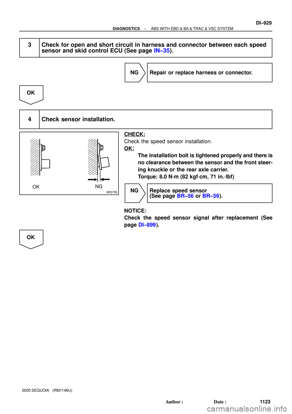
4 Check sensor installation.
CHECK:
Check the speed sensor installation.
OK:
The installation bolt is tightened properly and there is
no clearance between the sensor and the front steer-
ing knuckle or the rear axle carrier.
Torque: 8.0 N´m (82 kgf´cm, 71 in.´lbf)
NG Replace speed sensor
(See page BR±56 or BR±59).
NOTICE:
Check the speed sensor signal after replacement (See
page DI±899).
OK