Page 402 of 4323
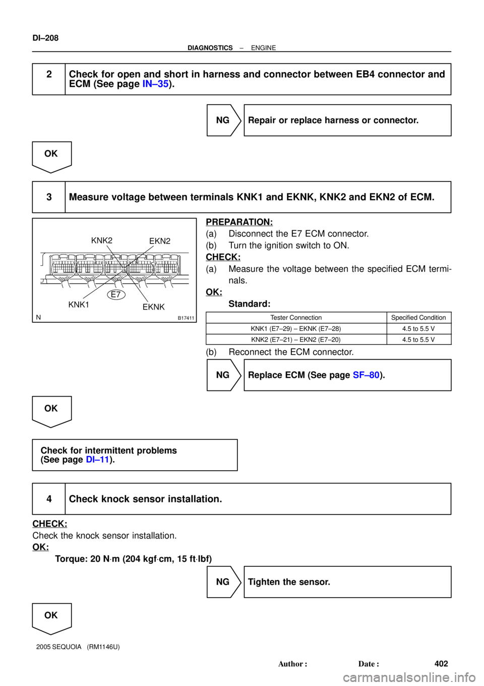
B17411
KNK1
KNK2EKN2
EKNK E7
DI±208
± DIAGNOSTICSENGINE
402 Author�: Date�:
2005 SEQUOIA (RM1146U)
2 Check for open and short in harness and connector between EB4 connector and
ECM (See page IN±35).
NG Repair or replace harness or connector.
OK
3 Measure voltage between terminals KNK1 and EKNK, KNK2 and EKN2 of ECM.
PREPARATION:
(a) Disconnect the E7 ECM connector.
(b) Turn the ignition switch to ON.
CHECK:
(a) Measure the voltage between the specified ECM termi-
nals.
OK:
Standard:
Tester ConnectionSpecified Condition
KNK1 (E7±29) ± EKNK (E7±28)4.5 to 5.5 V
KNK2 (E7±21) ± EKN2 (E7±20)4.5 to 5.5 V
(b) Reconnect the ECM connector.
NG Replace ECM (See page SF±80).
OK
Check for intermittent problems
(See page DI±11).
4 Check knock sensor installation.
CHECK:
Check the knock sensor installation.
OK:
Torque: 20 NVm (204 kgfVcm, 15 ftVlbf)
NG Tighten the sensor.
OK
Page 403 of 4323
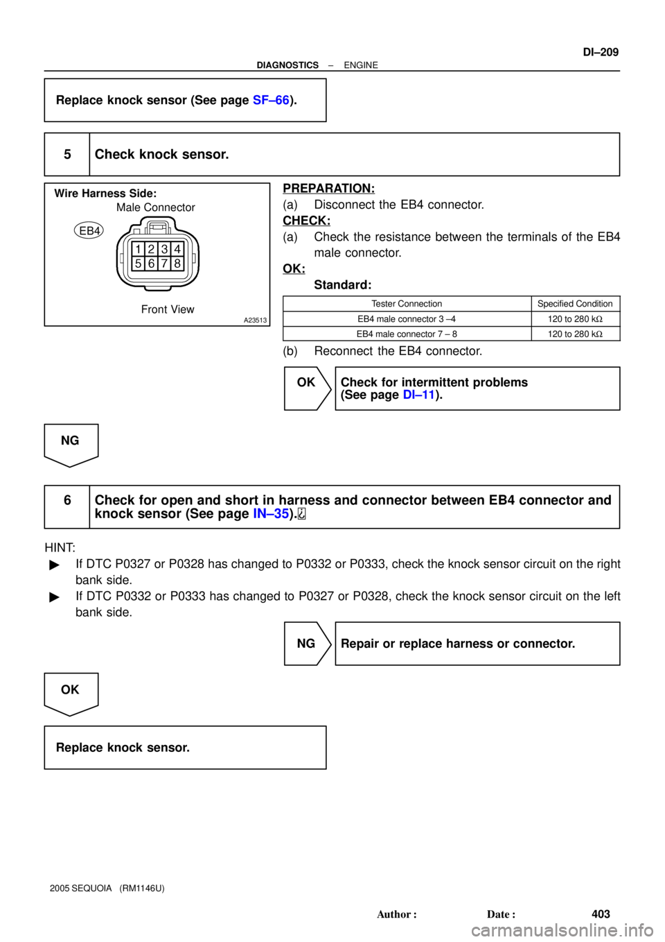
A23513
Male Connector
EB4
Wire Harness Side:
Front View
± DIAGNOSTICSENGINE
DI±209
403 Author�: Date�:
2005 SEQUOIA (RM1146U)
Replace knock sensor (See page SF±66).
5 Check knock sensor.
PREPARATION:
(a) Disconnect the EB4 connector.
CHECK:
(a) Check the resistance between the terminals of the EB4
male connector.
OK:
Standard:
Tester ConnectionSpecified Condition
EB4 male connector 3 ±4120 to 280 kW
EB4 male connector 7 ± 8120 to 280 kW
(b) Reconnect the EB4 connector.
OK Check for intermittent problems
(See page DI±11).
NG
6 Check for open and short in harness and connector between EB4 connector and
knock sensor (See page IN±35).
HINT:
�If DTC P0327 or P0328 has changed to P0332 or P0333, check the knock sensor circuit on the right
bank side.
�If DTC P0332 or P0333 has changed to P0327 or P0328, check the knock sensor circuit on the left
bank side.
NG Repair or replace harness or connector.
OK
Replace knock sensor.
Page 408 of 4323

2 Check for open a")
A21027
Wire Harness Side
Crankshaft Position Sensor C2
B17414
E6ECM Connector
NE± NE+
BR3795OK NGClearance
DI±214
± DIAGNOSTICSENGINE
408 Author�: Date�:
2005 SEQUOIA (RM1146U)
2 Check for open and short in harness and connector between ECM and
crankshaft position sensor.
PREPARATION:
(a) Disconnect the C2 crankshaft position sensor connector.
(b) Disconnect the E6 ECM connector.
CHECK:
Measure the resistance between the wire harness side connec-
tors.
OK:
Standard:
Tester ConnectionSpecified Condition
Crankshaft position sensor (C2±1) ±
NE+ (E6±21)Below 1 W
Crankshaft position sensor (C2±2) ±
NE± (E6±20)Below 1 W
Crankshaft position sensor (C2±1) or
NE+ (E6±21) ± Body ground10 kW or higher
Crankshaft position sensor (C2±2) or
NE± (E6±20) ± Body ground10 kW or higher
NG Repair or replace harness or connector.
OK
3 Check sensor installation (crankshaft position sensor).
CHECK:
Check the crankshaft position sensor installation.
OK:
The crankshaft position sensor is installed properly.
NG Tighten sensor installation bolt.
OK
Page 412 of 4323
DI±218
± DIAGNOSTICSENGINE
412 Author�: Date�:
2005 SEQUOIA (RM1146U)
TYPICAL MALFUNCTION THRESHOLDS
Detection CriteriaThreshold
P0340, P0345 Case 1:
VVT sensor signalNo signal
P0340, P0345 Case 2:
VVT sensor signalNo signal
P0341, P0346:
VVT sensor count12 or more / 720�CA (= Engine 2 revolutions)
COMPONENT OPERATING RANGE
ParameterStandard Value
VVT sensor signal input during every 720�CA3
WIRING DIAGRAM
Refer to DTC P0335 on page DI±210.
INSPECTION PROCEDURE
HINT:
Read freeze frame data using the hand-held tester. Freeze frame data records the engine conditions when
a malfunction is detected. When troubleshooting, freeze frame data can help determine if the vehicle was
running or stopped, if the engine was warmed up or not, if the air±fuel ratio was lean or rich, as well as other
data from the time when a malfunction occurred.
1 Check resistance of camshaft position sensor (See page SF±76).
NG Repair or replace harness or connector.
OK
Page 413 of 4323

2 Check for open")
B17414
E6
ECM Connector
VV2+
VV1±
VV1+VV2±
A21029
Wire Harness Side
VVT Sensor V16
V17
BR3795OK NGClearance
± DIAGNOSTICSENGINE
DI±219
413 Author�: Date�:
2005 SEQUOIA (RM1146U)
2 Check for open and short in harness and connector between ECM and VVT sen-
sor.
PREPARATION:
(a) Disconnect the VVT sensor connector.
(b) Disconnect the E6 ECM connector.
CHECK:
Measure the resistance between the wire harness side connec-
tors.
OK:
Standard:
Tester ConnectionSpecified Condition
VVT sensor (V16±1) ± VV1+ (E6±25)Below 1 W
VVT sensor (V16±2) ± VV1± (E6±24)Below 1 W
VVT sensor (V17±1) ± VV2+ (E6±18)Below 1 W
VVT sensor (V17±2) ± VV2± (E6±28)Below 1 W
VVT sensor (V16 ±1) or
VV1+ (E6±25) ± Body ground10 kW or higher
VVT sensor (V16±2) or
VV1± (E6±24) ± Body ground10 kW or higher
VVT sensor (V17 ±1) or
VV2+ (E6±18) ± Body ground10 kW or higher
VVT sensor (V17±2) or
VV2± (E6±28) ± Body ground10 kW or higher
NG Repair or replace harness or connector.
OK
3 Check sensor installation (VVT position sensor).
CHECK:
Check the VVT position sensor installation.
OK:
The VVT sensor is installed properly.
NG Tighten sensor installation bolt.
OK
Page 466 of 4323

DTC P0450 Evaporative Emission Control System Pres-
sure Sensor/Switch
DTC P0451 Evaporative Emission Control System Pres-
sur")
DI±264
± DIAGNOSTICSENGINE
458 Author�: Date�:
2005 SEQUOIA (RM1146U)
DTC P0450 Evaporative Emission Control System Pres-
sure Sensor/Switch
DTC P0451 Evaporative Emission Control System Pres-
sure Sensor/Switch Range/Performance
DTC P0452 Evaporative Emission Control System Pres-
sure Sensor/Switch Low Input
DTC P0453 Evaporative Emission Control System Pres-
sure Sensor/Switch High Input
DTC SUMMARY
DTCMonitoring ItemsMalfunction Detection ConditionsTrouble AreasDetection Tim-
ingsDetection
Logic
P0450Pressure sensor voltage ab-
normal fluctuationSensor output voltage rapidly fluctuates
beyond upper and lower malfunction
thresholds for 0.5 seconds.�Pump module
�Connector/Wire harness
(Pump module ± ECM)
�ECM�EVAP monitor-
ing (ignition
OFF)
�Ignition ON
1 trip
P0451Pressure sensor noisingSensor output voltage fluctuates fre-
quently in certain time period.
�Pump module
�Connector/Wire harness
(Pump module ± ECM)
�ECM�EVAP monitor-
ing (ignition
OFF)
�Engine running
2 trip
P0451Pressure sensor stuckSensor output voltage does vary in cer-
tain time period.
�Pump module
�Connector/Wire harness
(Pump module ± ECM)
�ECM�EVAP monitor-
ing (ignition
OFF)
2 trip
P0452Pressure sensor voltage lowSensor output voltage is less than 0.45
V for 0.5 seconds.
�Pump module
�Connector/Wire harness
(Pump module ± ECM)
�ECM�Ignition ON
�EVAP monitor-
ing (ignition
OFF)
1 trip
P0453Pressure sensor voltage highSensor output voltage is more than 4.9
V for 0.5 seconds.
�Pump module
�Connector/Wire harness
(Pump module ± ECM)
�ECM�Ignition ON
�EVAP monitor-
ing (ignition
OFF)
1 trip
HINT:
The pressure sensor is built into the pump module.
CIRCUIT DESCRIPTION
The circuit description can be found in the EVAP (Evaporative Emission) Inspection Procedure (see page
DI±460).
DID89±01
Page 470 of 4323

INSPECTION PROCEDURE
NOTICE:
�When a vehicle is brought into the workshop, leave it as it is. Do not change the vehicle condi-")
DI±268
± DIAGNOSTICSENGINE
462 Author�: Date�:
2005 SEQUOIA (RM1146U)
INSPECTION PROCEDURE
NOTICE:
�When a vehicle is brought into the workshop, leave it as it is. Do not change the vehicle condi-
tion. For example, do not tighten the fuel tank cap.
�Do not disassemble the pump module.
�A hand±held tester is required to conduct the following diagnostic troubleshooting procedure.
1 Confirm DTC and EVAP pressure.
PREPARATION:
(a) Connect a hand±held tester to the DLC3.
(b) Turn the ignition switch to ON (do not start the engine).
(c) Turn the tester ON.
CHECK:
(a) Select the following menu items: DIAGNOSIS / ENHANCED OBD II / DTC INFO / CURRENT CODES.
(b) Read DTCs.
(c) Select the following menu items: DIAGNOSIS / ENHANCED OBD II / DATA LIST / ALL / VAPOR
PRESS.
(d) Read the EVAP (Evaporative Emission) pressure displayed on the tester.
RESULT:
Display (DTC Output)Test ResultsSuspected Trouble AreasProceed To
P0451'�Pressure sensorC
P0452Less than 45 kpa (430 mmHg)
�Wire harness/connector (ECM ± pressure
sensor)
�Pressure sensor
�Short in ECM circuit
A
P0453More than 120 kPa (900 mmHg)
�Wire harness/connector (ECM ± pressure
sensor)
�Pressure sensor
�Open in ECM circuit
B
B Go to step 4.
C Go to EVAP inspection procedure
(See page DI±460).
A
Page 471 of 4323
B17417
E4
PPMP
± DIAGNOSTICSENGINE
DI±269
463 Author�: Date�:
2005 SEQUOIA (RM1146U)
2 Measure resistance between terminal PPMP of ECM and body ground.
PREPARATION:
(a) Turn the ignition switch to OFF.
(b) Disconnect the E4 ECM connector.
CHECK:
Measure the resistance between PPMP terminal of the ECM
connector and the body ground.
RESULT:
Test ResultsSuspected Trouble AreasProceed To
10 W or less�Wire harness/connector (ECM ± pressure sensor)
�Short in pressure sensor circuitA
10 kW or more�Wire harness/connector (ECM ± pressure sensor)
�Short in ECM circuitB
B Go to step 7.
A