Page 584 of 4323

2")
A21022
Wire Harness Side:
A37
Accelerator Pedal Position Sensor
VCP2
EPA2
VPA2
VCPAEPAVPA
B17417
E4VPA2
VCPAVPA
EPA2
EPAVCP2
DI±382
± DIAGNOSTICSENGINE
576 Author�: Date�:
2005 SEQUOIA (RM1146U)
2 Check for open and short in harness and connector between accelerator pedal
position sensor and ECM.
PREPARATION:
(a) Disconnect the A37 accelerator pedal position sensor
connector.
(b) Disconnect the E4 ECM connector.
CHECK:
Measure the resistance between the wire harness side connec-
tors.
OK:
Standard (Check for open):
Tester ConnectionSpecified Condition
VPA (A37±6) ± VPA (E4±18)Below 1 W
EPA (A37±5) ± EPA (E4±20)Below 1 W
VCPA (A37±4) ± VCPA (E4±26)Below 1 W
VPA2 (A37±3) ± VPA2 (E4±19)Below 1 W
EPA2 (A37±2) ± EPA2 (E4±21)Below 1 W
VCP2 (A37±1) ± VCP2 (E4±27)Below 1 W
Standard (Check for short):
Tester ConnectionSpecified Condition
VPA (A37±6) or VPA (E4±18) ±
Body ground10 kW or higher
EPA (A37±5) or EPA (E4±20) ±
Body ground10 kW or higher
VCPA (A37±4) or VCPA (E4±26) ±
Body ground10 kW or higher
VPA2 (A37±3) or VPA2 (E4±19) ±
Body ground10 kW or higher
EPA2 (A37±2) or EPA2 (E4±21) ±
Body ground10 kW or higher
VCP2 (A37±1) or VCP2 (E4±27) ±
Body ground10 kW or higher
NG Repair or replace harness or connector.
OK
Replace accelerator pedal pedal assembly.
Page 600 of 4323
:
A")
A23659
Wire Harness Side:
HT
A38
Sensor 1A/F Sensor Connector
AF+
Front ViewAF±
+B A39
B17415A55007
E7ECM Connector
HA1A
A1A+
A1A±
A2A+
A2A±HA2A
A23512
Reference (Bank 1 Sensor 1 System Drawing):
A/F Sensor A/F Relay
Heater
Sensor
A1A+ HA1A
Duty
Control ECM
From
Battery
A/F Heater
Fuse
A1A±
To EFI Relay DI±398
± DIAGNOSTICSENGINE
592 Author�: Date�:
2005 SEQUOIA (RM1146U)
12 Check for open and short in harness and connector between ECM and A/F sen-
sor.
PREPARATION:
(a) Disconnect the A38 or A39 A/F sensor connector.
(b) Turn the ignition switch to ON.
CHECK:
(a) Measure the voltage between the +B terminal of the A/F
sensor connector and body ground.
Standard:
Tester ConnectionsSpecified Conditions
+B (2) ± Body groundBetween 9 V and 14 V
PREPARATION:
(a) Turn the ignition switch to OFF.
(b) Disconnect the E7 ECM connector.
CHECK:
(a) Check the resistance.
Standard (Check for open):
Tester ConnectionsSpecified Conditions
HT (A38±1) ± HA1A (E7±2)
HT (A39±1) ± HA2A (E7±1)Below 1 W
AF+ (A38±3) ± A1A+ (E7±22)
AF+ (A39±3) ± A2A+ (E7±23)Below 1 W
AF± (A38±4) ± A1A± (E7±30)
AF± (A39±4) ± A2A± (E7±31)Below 1 W
Standard (Check for short):
Tester ConnectionsSpecified Conditions
HT (A38±1) or HA1A (E7±2) ± Body ground
HT (A39±1) or HA2A (E7±1) ± Body ground10 kW or higher
AF+ (A38±3) or A1A+ (E7±22) ± Body ground
AF+ (A39±3) or A2A+ (E7±23) ± Body ground10 kW or higher
AF± (A38±4) or A1A± (E7±30) ± Body ground
AF± (A39±4) or A2A± (E7±31) ± Body ground10 kW or higher
Page 610 of 4323
:
A")
A23659
Wire Harness Side:
HT
A38
Sensor 1A/F Sensor Connector
AF+
Front ViewAF±
+B A39
B17415A55007
E7ECM Connector
HA1A
A1A+
A1A±
A2A+
A2A±HA2A
A23512
Reference (Bank 1 Sensor 1 System Drawing):
A/F Sensor A/F Relay
Heater
Sensor
A1A+ HA1A
Duty
Control ECM
From
Battery
A/F Heater
Fuse
A1A±
To EFI Relay DI±408
± DIAGNOSTICSENGINE
602 Author�: Date�:
2005 SEQUOIA (RM1146U)
3 Check for open and short in harness and connector between ECM and A/F sen-
sor.
PREPARATION:
(a) Disconnect the A38 or A39 A/F sensor connector.
(b) Turn the ignition switch to ON.
CHECK:
(a) Measure the voltage between the +B terminal of the A/F
sensor connector and body ground.
OK:
Standard:
Tester ConnectionsSpecified Conditions
+B (2) ± Body groundBetween 9 V and 14 V
PREPARATION:
(a) Turn the ignition switch to OFF.
(b) Disconnect the E7 ECM connector.
CHECK:
(a) Check the resistance.
OK:
Standard (Check for open):
Tester ConnectionsSpecified Conditions
HT (A38±1) ± HA1A (E7±2)
HT (A39±1) ± HA2A (E7±1)Below 1 W
AF+ (A38±3) ± A1A+ (E7±22)
AF+ (A39±3) ± A2A+ (E7±23)Below 1 W
AF± (A38±4) ± A1A± (E7±30)
AF± (A39±4) ± A2A± (E7±31)Below 1 W
Standard (Check for short):
Tester ConnectionsSpecified Conditions
HT (A38±1) or HA1A (E7±2) ± Body ground
HT (A39±1) or HA2A (E7±1) ± Body ground10 kW or higher
AF+ (A38±3) or A1A+ (E7±22) ± Body ground
AF+ (A39±3) or A2A+ (E7±23) ± Body ground10 kW or higher
AF± (A38±4) or A1A± (E7±30) ± Body ground
AF± (A39±4) or A2A± (E7±31) ± Body ground10 kW or higher
Page 626 of 4323
A23557
ECM A42
Air Pressure Sensor
VC
AIP
E2
E8 E8 E8
2832 23
VC
AIP
E2EB4
EB4
EB4G±B G±B
B±Y
B±Y
G±W
G±W6 5 15 V
B17412
E8
E2AIP VC
B17439
Wire Harness Side:
Pressure Sensor Connector
A42
E2
AIP VC
DI±424
± DIAGNOSTICSENGINE
618 Author�: Date�:
2005 SEQUOIA (RM1146U)
WIRING DIAGRAM
INSPECTION PROCEDURE
1 Check for open and short in harness and connector between pressure sensor
and ECM (See page IN±35).
PREPARATION:
(a) Remove the intake manifold (see page EM±36).
(b) Disconnect the A42 pressure sensor connector.
(c) Disconnect the E8 ECM connector.
CHECK:
Measure the resistance between the wire harness side connec-
tors.
OK:
Standard:
Tester ConnectionSpecified Condition
VC (A42±1) ± VC (E8±23)
AIP (A42±2) ± AIP (E8±32)
E2 (A42±3) ± AIP (E8±28)
Below 1 W
VC (A42±1) or VC (E8±23) ±
Body ground
AIP (A42±2) or AIP (E8±32) ±
Body ground
10 kW or higher
NG Repair or replace harness and connector.
OK
Page 659 of 4323
:
A")
A23659
Wire Harness Side:
HT
A38
Sensor 1A/F Sensor Connector
AF+
Front ViewAF±
+B A39
B17415A55007
E7ECM Connector
HA1A
A1A+
A1A±
A2A+
A2A±HA2A
A23512
Reference (Bank 1 Sensor 1 System Drawing):
A/F Sensor A/F Relay
Heater
Sensor
A1A+ HA1A
Duty
Control ECM
From
Battery
A/F Heater
Fuse
A1A±
To EFI Relay
± DIAGNOSTICSENGINE
DI±457
651 Author�: Date�:
2005 SEQUOIA (RM1146U)
3 Check for open and short in harness and connector between ECM and A/F sen-
sor.
PREPARATION:
(a) Disconnect the A38 or A39 A/F sensor connector.
(b) Turn the ignition switch to ON.
CHECK:
(a) Measure the voltage between the +B terminal of the A/F
sensor connector and body ground.
OK:
Standard:
Tester ConnectionsSpecified Conditions
+B (2) ± Body groundBetween 9 V and 14 V
PREPARATION:
(a) Turn the ignition switch to OFF.
(b) Disconnect the E7 ECM connector.
CHECK:
(a) Check the resistance.
OK:
Standard (Check for open):
Tester ConnectionsSpecified Conditions
HT (A38±1) ± HA1A (E7±2)
HT (A39±1) ± HA2A (E7±1)Below 1 W
AF+ (A38±3) ± A1A+ (E7±22)
AF+ (A39±3) ± A2A+ (E7±23)Below 1 W
AF± (A38±4) ± A1A± (E7±30)
AF± (A39±4) ± A2A± (E7±31)Below 1 W
Standard (Check for short):
Tester ConnectionsSpecified Conditions
HT (A38±1) or HA1A (E7±2) ± Body ground
HT (A39±1) or HA2A (E7±1) ± Body ground10 kW or higher
AF+ (A38±3) or A1A+ (E7±22) ± Body ground
AF+ (A39±3) or A2A+ (E7±23) ± Body ground10 kW or higher
AF± (A38±4) or A1A± (E7±30) ± Body ground
AF± (A39±4) or A2A± (E7±31) ± Body ground10 kW or higher
Page 660 of 4323
DI±458
± DIAGNOSTICSENGINE
652 Author�: Date�:
2005 SEQUOIA (RM1146U)
NG Replace or replace harness or connector.
OK
4 Perform confirmation driving pattern.
NEXT
5 Check whether DTC output recurs (DTC P2A00 or P2A03)
CHECK:
(a) On the hand±held tester, select the following menu items: DIAGNOSIS / ENHANCED OBD II / DTC
INFO / PENDING CODES.
(b) Read DTCs.
RESULT:
Display (DTC Output)Proceed To
P2A00 or P2A03A
No outputB
B Check for intermittent problems
(See page DI±11).
A
6 Replace air fuel ratio sensor.
NEXT
7 Perform confirmation driving pattern.
NEXT
Page 778 of 4323

CIRCUIT INSPECTION
DTC P0705 Transmission Range Sensor Circuit Mal-
function (PRNDL Input)
CIRCUIT D")
DIDJ5±01
DI±576
± DIAGNOSTICSAUTOMATIC TRANSMISSION
770 Author�: Date�:
2005 SEQUOIA (RM1146U)
CIRCUIT INSPECTION
DTC P0705 Transmission Range Sensor Circuit Mal-
function (PRNDL Input)
CIRCUIT DESCRIPTION
The park/neutral position switch detects the shift lever position and sends signals to the ECM.
DTC No.DTC Detection ConditionTrouble Area
P0705
(2±trip detection logic)
�All switches are OFF simultaneously for NSW, R, N, D, 3 and
2 positions.
�2 or more switches are ON simultaneously for NSW, R, D, 3
and 2 positions.
�Open or short in park/neutral position switch circuit
�Park/neutral position switch
�ECM
MONITOR DESCRIPTION
These DTCs indicate a problem with the park/neutral position switch and the wire harness in the park/neutral
position switch circuit.
The park/neutral position switch detects the shift lever position and sends a signal to the ECM.
For security, the park/neutral position switch detects the shift lever position so that engine can be started
only when the shift lever is in the P or N position.
The park/neutral position switch sends a signal to the ECM according to the shift position (NSW, R, D, 3 or
2).
The ECM determines that there is a problem with the switch or related parts if it receives more than 1 position
signal simultaneously. The ECM will turn on the MIL and store the DTC.
MONITOR STRATEGY
Related DTCsP0705Park/neutral position switch/Verify switch input
Required sensors/ComponentsPark/neutral position switch
Frequency of operationContinuous
DtiCondition (A)2 sec.DurationCondition (B)60 sec.
MIL operation2 driving cycle
Sequence of operationNone
TYPICAL ENABLING CONDITIONS
ItSpecificationItemMinimumMaximum
The monitor will run whenever this DTC is
not present.See page DI±545
Ignition switchON
Battery voltage10.5 V or more
Page 797 of 4323
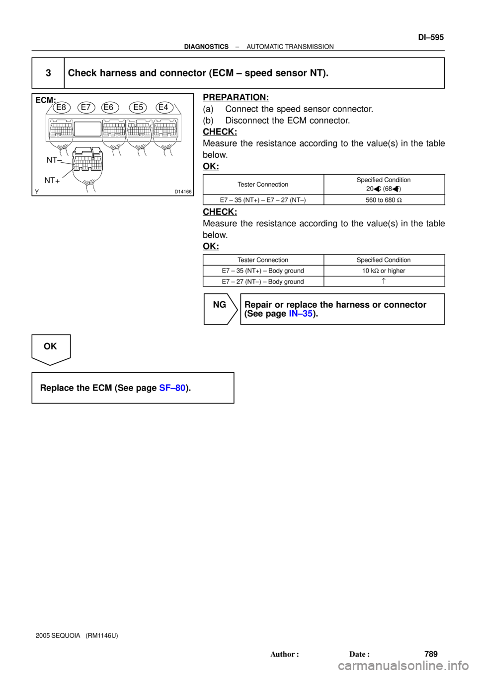
D14166
ECM:
NT+NT±E8E7E6E5E4
± DIAGNOSTICSAUTOMATIC TRANSMISSION
DI±595
789 Author�: Date�:
2005 SEQUOIA (RM1146U)
3 Check harness and connector (ECM ± speed sensor NT).
PREPARATION:
(a) Connect the speed sensor connector.
(b) Disconnect the ECM connector.
CHECK:
Measure the resistance according to the value(s) in the table
below.
OK:
Tester ConnectionSpecified Condition
20�C (68�F)
E7 ± 35 (NT+) ± E7 ± 27 (NT±)560 to 680 W
CHECK:
Measure the resistance according to the value(s) in the table
below.
OK:
Tester ConnectionSpecified Condition
E7 ± 35 (NT+) ± Body ground10 kW or higher
E7 ± 27 (NT±) ± Body ground=
NG Repair or replace the harness or connector
(See page IN±35).
OK
Replace the ECM (See page SF±80).