Page 894 of 4323
D14180
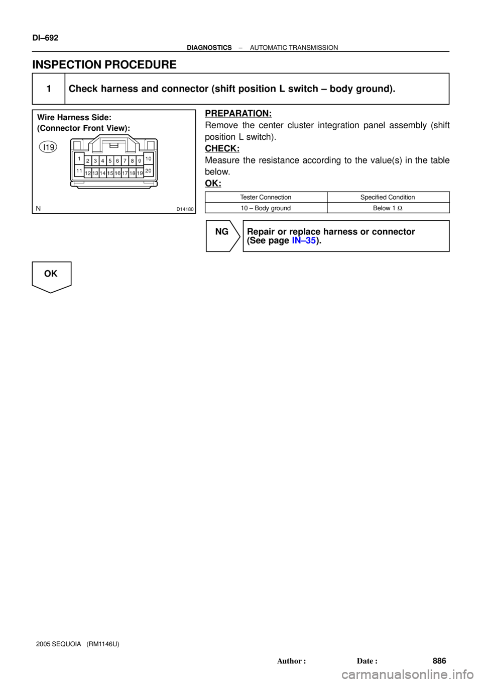
Wire Harness Side:
(Connector Front View):
I19
DI±692
± DIAGNOSTICSAUTOMATIC TRANSMISSION
886 Author�: Date�:
2005 SEQUOIA (RM1146U)
INSPECTION PROCEDURE
1 Check harness and connector (shift position L switch ± body ground).
PREPARATION:
Remove the center cluster integration panel assembly (shift
position L switch).
CHECK:
Measure the resistance according to the value(s) in the table
below.
OK:
Tester ConnectionSpecified Condition
10 ± Body groundBelow 1 W
NG Repair or replace harness or connector
(See page IN±35).
OK
Page 895 of 4323
D14236
I19I22GND2LO
± DIAGNOSTICSAUTOMATIC TRANSMISSION
DI±693
887 Author�: Date�:
2005 SEQUOIA (RM1146U)
2 Inspect center cluster integration panel (shift position L switch).
CHECK:
Measure the resistance according to the value(s) in the table
below.
OK:
Switch ConditionTester ConnectionSpecified Condition
Shift position L switch
pressed and heldI22 ± 1 (2LO) ±
I19 ± 10 (GND)Below 1 W
Shift position L switch
released=10 kW or higher
NG Replace center cluster integration panel
(shift position L switch).
OK
Page 896 of 4323
D14184
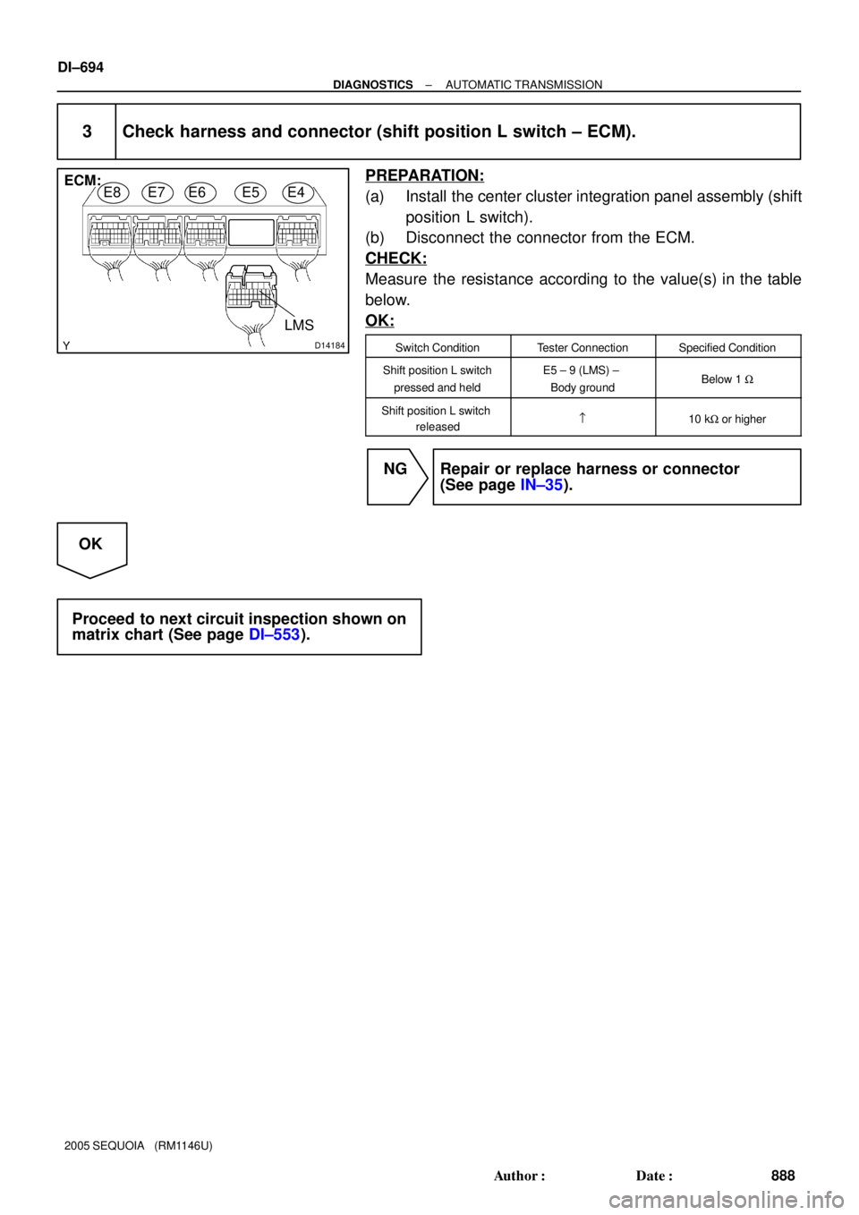
E8E7E6E5E4ECM:
LMS
DI±694
± DIAGNOSTICSAUTOMATIC TRANSMISSION
888 Author�: Date�:
2005 SEQUOIA (RM1146U)
3 Check harness and connector (shift position L switch ± ECM).
PREPARATION:
(a) Install the center cluster integration panel assembly (shift
position L switch).
(b) Disconnect the connector from the ECM.
CHECK:
Measure the resistance according to the value(s) in the table
below.
OK:
Switch ConditionTester ConnectionSpecified Condition
Shift position L switch
pressed and heldE5 ± 9 (LMS) ±
Body groundBelow 1 W
Shift position L switch
released=10 kW or higher
NG Repair or replace harness or connector
(See page IN±35).
OK
Proceed to next circuit inspection shown on
matrix chart (See page DI±553).
Page 3449 of 4323
I24334
Turn Signal Flasher Relay
Connector Front View:
I28728
10
19
± BODY ELECTRICALTURN SIGNAL AND HAZARD WARNING SYSTEM
BE±37
3441 Author�: Date�:
2005 SEQUOIA (RM1146U)
3. Connector connected:
INSPECT TURN SIGNAL FLASHER RELAY OPERA-
TION
Connect the wire harness side connector to the turn signal
flasher and inspect the connector from the back side, as shown.
Tester connectionConditionSpecified condition
2 ± GroundTurn signal switch RIGHTBattery positive voltage e 0 V
3 ± GroundTurn signal switch LEFTBattery positive voltage e 0 V
If operation is not as specified, replace the relay.
4. INSPECT HAZARD WARNING SWITCH CONTINUITY
(a) Remove the center cluster finish panel.
(b) Disconnect the connector from the integrated center clus-
ter.
(c) Check that continuity exists between terminals 19 and 10
with the switch ON.
(d) Check that no continuity exists between terminals 19 and
10 with the switch OFF.
If continuity is not as specified, replace the switch.
Page 3470 of 4323

11. INSPECT WASHER LEVEL SWITCH CONTINUI")
N07797
OFF
ON
BE0044
Warning Light
Ignition
Switch
Battery
I28507
4
10
BE±58
± BODY ELECTRICALCOMBINATION METER
3462 Author�: Date�:
2005 SEQUOIA (RM1146U)
11. INSPECT WASHER LEVEL SWITCH CONTINUITY
(a) Check that there is no continuity between terminals with
the switch OFF (float up).
(b) Check that there is continuity between terminals with the
switch ON (float down).
If operation is not as specified, replace the jar & pump assem-
bly.
12. INSPECT BUCKLE SWITCH CONTINUITY
(See page DI±1126)
13. INSPECT OPEN DOOR WARNING LIGHT OPERATION
(a) Disconnect the connector from the door courtesy switch
and ground terminal on the wire harness side connector.
(b) Check that the warning light comes on.
If the warning light does not come on, test the bulb.
14. INSPECT PASSENGER SEAT BELT WARNING LIGHT
(a) Remove the center cluster finish panel.
(b) Disconnect the connectors from the center cluster in-
tegration.
(c) Connect the positive (+) lead from the battery to terminal
4 and the negative (±) lead to terminal 10, and check that
the warning light comes on.
If the warning light does not come on, inspect the bulb or wire
harness (See page DI±1126).
Page 3646 of 4323

BO4S5±01
H24375
Instrument Panel ReinforcementFront Passenger Airbag Assembly
Lower No. 2
Finish Panel
No. 2 Brace
Center Heater to
Register Duct
No. 1 Brace
No. 2 Heater to
Register DuctNo. 4 Heater to
Register DuctAssist Grip Plug
Instrument Panel
Radio Tuner
Assembly Assist Grip
Front Pillar Garnish
Combination Meter Switch Base
Lower Finish PanelGlove Compartment
Door
Side Panel
Cowl Side
Trim Board
Cluster
Finish
Panel
Console Box
BezelUpper
Console Panel w/ Seat heater:
Seat Heater Switch
Steering
Wheel Pad Front Console Box
Lower
Steering
Column Cover
Front Door
Scuff Plate
N´m (kgf´cm, ft´lbf): Specified torque
CC
G
G
C
G
G
G
GC
CC
C
DDD
DD
A
A
A
A
AA
AA
F
FF
DD
D
DB
BB
B
5.0 (51, 44 in.´lbf)
20 (204, 15)
A
A
Headphone
Terminal
8.8 (90, 78 in.´lbf)
Lower No. 2
CoverLower No. 3
Cover
AAAA
Headphone
TerminalRear Console
Box w/ Rear seat entertainment :
w/ Rear heater A/C:
Rear Heater Control
Panel
w/ Rear seat
entertainment :
Disc Player
Coverw/ Rear heater A/C:
Disc Player
w/o
Rear heater
A/C:
Rear Heater
Control PanelHeater
Control
Panel
w/ Rear seat audio or rear
seat entertainment:
8.8 (90, 78 in.´lbf)
Steering Wheel
Upper Steering Column Cover
Front Door
Scuff Plate
Side Panel
Cowl Side Trim Board
5.0 (51, 44 in.´lbf)
Integration
Control Panel
Combination Switch
50 (510, 37)
Front Pillar Garnish
Lower Instrument Cover
Shifting Hole
Cover
Door Control
Receiver
Assist Grip Plug
H
B
± BODYINSTRUMENT PANEL
BO±85
3638 Author�: Date�:
2005 SEQUOIA (RM1146U)
INSTRUMENT PANEL
COMPONENTS
Page 3651 of 4323

10. REMOVE LOWER FINISH PANEL
(a) Remove the 2 screws")
H11174: 4 Clips
H11372
3 Clips
H11177
2 Clips
H16769
5 Clips
H24384
BO±90
± BODYINSTRUMENT PANEL
3643 Author�: Date�:
2005 SEQUOIA (RM1146U)
10. REMOVE LOWER FINISH PANEL
(a) Remove the 2 screws and hood lock release lever.
(b) Remove the 4 bolts and lower finish panel.
(c) Disconnect the connector.
11. REMOVE SWITCH BASE
(a) Using a screwdriver, lift up the switch base and remove it.
HINT:
Tape the screwdriver tip before use.
(b) Disconnect the connectors.
12. REMOVE NO. 2 HEATER TO REGISTER DUCT
13. REMOVE STEERING COLUMN (See page SR±14)
14. REMOVE CLUSTER FINISH PANEL
Remove the 2 screws and cluster finish panel.
15. REMOVE COMBINATION METER
(a) Remove the 4 screws.
(b) Remove the combination meter and disconnect the 4
connectors.
16. REMOVE INTEGRATION CONTROL PANEL
(a) Remove the 2 screws as shown in the illustration.
(b) Using a screwdriver, remove the integration panel, then
disconnect the connectors.
HINT:
Tape the screwdriver tip before use.
17. REMOVE RADIO TUNER ASSEMBLY
(a) Disconnect the connector.
(b) Remove the 4 bolts and radio tuner assembly.
18. REMOVE AIR CONDITIONER CONTROL ASSEMBLY
(See page AC±103)
Page 3837 of 4323
AC3I1±03
I21397
Center Cluster
Integration Panel
Heater
Control
Housing
A/C Amplifier
Seat Belt Indicator Circuit
BulbBulb
Bulb
Knob
Knob
Knob
Integration Panel
Knob
AC±102± AIR CONDITIONINGAIR CONDITIONER CONTROL ASSEMBLY (Center
Cluster Integration)
3829 Author�: Date�:
2005 SEQUOIA (RM1146U)
AIR CONDITIONER CONTROL ASSEMBLY (Center Cluster
Integration)
COMPONENTS