Page 2606 of 4323

A23310
String
A04339
A23311
Slightly Turn
A23312
SST
± ENGINE MECHANICALTIMING BELT
EM±19
2598 Author�: Date�:
2005 SEQUOIA (RM1146U)
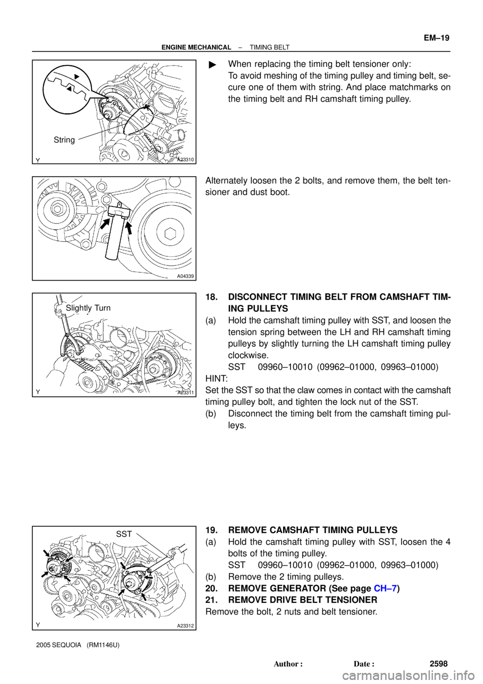
�When replacing the timing belt tensioner only:
To avoid meshing of the timing pulley and timing belt, se-
cure one of them with string. And place matchmarks on
the timing belt and RH camshaft timing pulley.
Alternately loosen the 2 bolts, and remove them, the belt ten-
sioner and dust boot.
18. DISCONNECT TIMING BELT FROM CAMSHAFT TIM-
ING PULLEYS
(a) Hold the camshaft timing pulley with SST, and loosen the
tension spring between the LH and RH camshaft timing
pulleys by slightly turning the LH camshaft timing pulley
clockwise.
SST 09960±10010 (09962±01000, 09963±01000)
HINT:
Set the SST so that the claw comes in contact with the camshaft
timing pulley bolt, and tighten the lock nut of the SST.
(b) Disconnect the timing belt from the camshaft timing pul-
leys.
19. REMOVE CAMSHAFT TIMING PULLEYS
(a) Hold the camshaft timing pulley with SST, loosen the 4
bolts of the timing pulley.
SST 09960±10010 (09962±01000, 09963±01000)
(b) Remove the 2 timing pulleys.
20. REMOVE GENERATOR (See page CH±7)
21. REMOVE DRIVE BELT TENSIONER
Remove the bolt, 2 nuts and belt tensioner.
Page 2629 of 4323

A02859
A02850
SST
Service Bolt
Turn
A02861
A23341
Do Not Remove
A23342
10 mm
Hexagon
Wrench
EM±42
± ENGINE MECHANICALCYLINDER HEAD
2621 Author�: Date�:
2005 SEQUOIA (RM1146U)
25. DISASSEMBLE EXHAUST CAMSHAFTS
(a) Mount the hexagon head portion of the camshaft in a vise.
NOTICE:
Be careful not to damage the camshaft.
(b) Using SST, turn the sub±gear clockwise, and remove the
service bolt.
SST 09960±10010 (09962±01000, 09963±00500)
(c) Using snap ring pliers, remove the snap ring.
(d) Remove the wave washer.
(e) Remove the camshaft sub±gear.
(f) Remove the camshaft gear spring.
NOTICE:
Be careful not to damage the camshaft.
26. REMOVE CAMSHAFT TIMING TUBE FROM INTAKE
CAMSHAFT
(a) Mount the hexagon head portion of the intake camshaft
in a vise.
NOTICE:
�Be careful not to damage the camshaft.
�The 4 bolts shown in the illustration determine back-
lash of the gear in the timing tube, so do not remove
them. If any of the 4 bolts are removed, install a new
timing tube assembly.
(b) Remove the screw plug and seal washer.
(c) Using a 10 mm hexagon wrench, and remove the bolt.
(d) Pull out the timing tube and drive gear assembly from the
camshaft.
Page 3259 of 4323

F13260
F17896
BMatchmarks
A
F19948
Mark
SR±24
± STEERINGTILT STEERING COLUMN
3251 Author�: Date�:
2005 SEQUOIA (RM1146U)
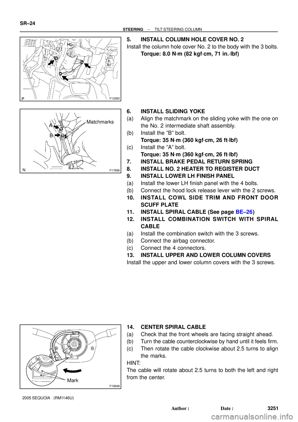
5. INSTALL COLUMN HOLE COVER NO. 2
Install the column hole cover No. 2 to the body with the 3 bolts.
Torque: 8.0 N´m (82 kgf´cm, 71 in.´lbf)
6. INSTALL SLIDING YOKE
(a) Align the matchmark on the sliding yoke with the one on
the No. 2 intermediate shaft assembly.
(b) Install the ºBº bolt.
Torque: 35 N´m (360 kgf´cm, 26 ft´lbf)
(c) Install the ºAº bolt.
Torque: 35 N´m (360 kgf´cm, 26 ft´lbf)
7. INSTALL BRAKE PEDAL RETURN SPRING
8. INSTALL NO. 2 HEATER TO REGISTER DUCT
9. INSTALL LOWER LH FINISH PANEL
(a) Install the lower LH finish panel with the 4 bolts.
(b) Connect the hood lock release lever with the 2 screws.
10. INSTALL COWL SIDE TRIM AND FRONT DOOR
SCUFF PLATE
11. INSTALL SPIRAL CABLE (See page BE±26)
12. INSTALL COMBINATION SWITCH WITH SPIRAL
CABLE
(a) Install the combination switch with the 3 screws.
(b) Connect the airbag connector.
(c) Connect the 4 connectors.
13. INSTALL UPPER AND LOWER COLUMN COVERS
Install the upper and lower column covers with the 3 screws.
14. CENTER SPIRAL CABLE
(a) Check that the front wheels are facing straight ahead.
(b) Turn the cable counterclockwise by hand until it feels firm.
(c) Then rotate the cable clockwise about 2.5 turns to align
the marks.
HINT:
The cable will rotate about 2.5 turns to both the left and right
from the center.