Page 1032 of 2267
Diagnostic ProcedureNCEC0211
1 RETIGHTEN GROUND SCREWS
Loosen and retighten engine ground screws.
SEF202X
©GO TO 2.
2 CHECK INPUT SIGNAL CIRCUIT-1
1. Turn ignition switch ªOFFº.
2. Disconnect ECM harness connector and knock sensor harness connector.
SEF210X3. Check harness continuity between knock sensor signal terminal 2 and ECM terminal 81.
Refer to wiring diagram.
Continuity should exist.
4. Also check harness for short to ground and short to power.
OK or NG
OK©GO TO 4.
NG©GO TO 3.
3 DETECT MALFUNCTIONING PART
Check the harness for open or short between knock sensor and ECM.
©Repair open circuit or short to ground or short to power in harness or connectors.
4 CHECK KNOCK SENSOR
Knock sensor
Refer to ªComponent Inspectionº, EC-SR-233.
OK or NG
OK©GO TO 5.
NG©Replace knock sensor.
Intake manifold collector
Engine ground
Knock sensor Knock sensor harness connector
Drive shaft View from under the vehicle
DTC P0325 KNOCK SENSOR (KS)SR20DE
Diagnostic Procedure
EC-232
Page 1036 of 2267
Wiring DiagramNCEC0581
YEC839
: Detectable line for DTC
: Non-detectable line for DTC
: Hyper CVT models
ECMTCM
(TRANSMISSION
CONTROL
MODULE) CRANKSHAFT
POSITION
SENSOR (OBD)
DTC P0335 CRANKSHAFT POSITION SENSOR (CKPS) (OBD)SR20DE
Wiring Diagram
EC-236
Page 1037 of 2267

Diagnostic ProcedureNCEC0582
1 RETIGHTEN GROUND SCREWS
1. Turn ignition switch ªOFFº.
2. Loosen and retighten engine ground screws.
©GO TO 2.
2 CHECK INPUT SIGNAL CIRCUIT
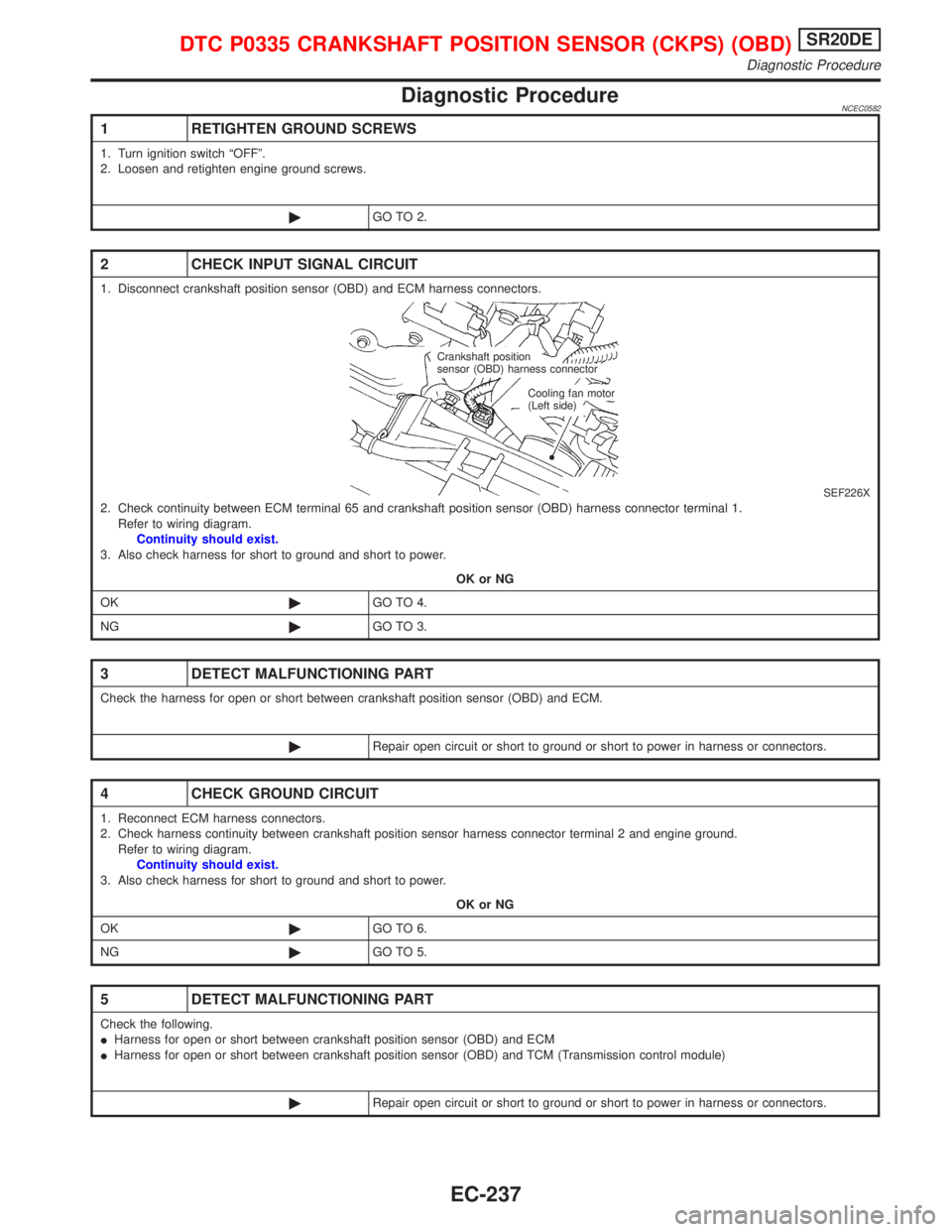
1. Disconnect crankshaft position sensor (OBD) and ECM harness connectors.
SEF226X2. Check continuity between ECM terminal 65 and crankshaft position sensor (OBD) harness connector terminal 1.
Refer to wiring diagram.
Continuity should exist.
3. Also check harness for short to ground and short to power.
OK or NG
OK©GO TO 4.
NG©GO TO 3.
3 DETECT MALFUNCTIONING PART
Check the harness for open or short between crankshaft position sensor (OBD) and ECM.
©Repair open circuit or short to ground or short to power in harness or connectors.
4 CHECK GROUND CIRCUIT
1. Reconnect ECM harness connectors.
2. Check harness continuity between crankshaft position sensor harness connector terminal 2 and engine ground.
Refer to wiring diagram.
Continuity should exist.
3. Also check harness for short to ground and short to power.
OK or NG
OK©GO TO 6.
NG©GO TO 5.
5 DETECT MALFUNCTIONING PART
Check the following.
IHarness for open or short between crankshaft position sensor (OBD) and ECM
IHarness for open or short between crankshaft position sensor (OBD) and TCM (Transmission control module)
©Repair open circuit or short to ground or short to power in harness or connectors.
Crankshaft position
sensor (OBD) harness connector
Cooling fan motor
(Left side)
DTC P0335 CRANKSHAFT POSITION SENSOR (CKPS) (OBD)SR20DE
Diagnostic Procedure
EC-237
Page 1042 of 2267
Wiring DiagramNCEC0224
YEC090A
DTC P0340 CAMSHAFT POSITION SENSOR (CMPS)SR20DE
Wiring Diagram
EC-242
Page 1044 of 2267

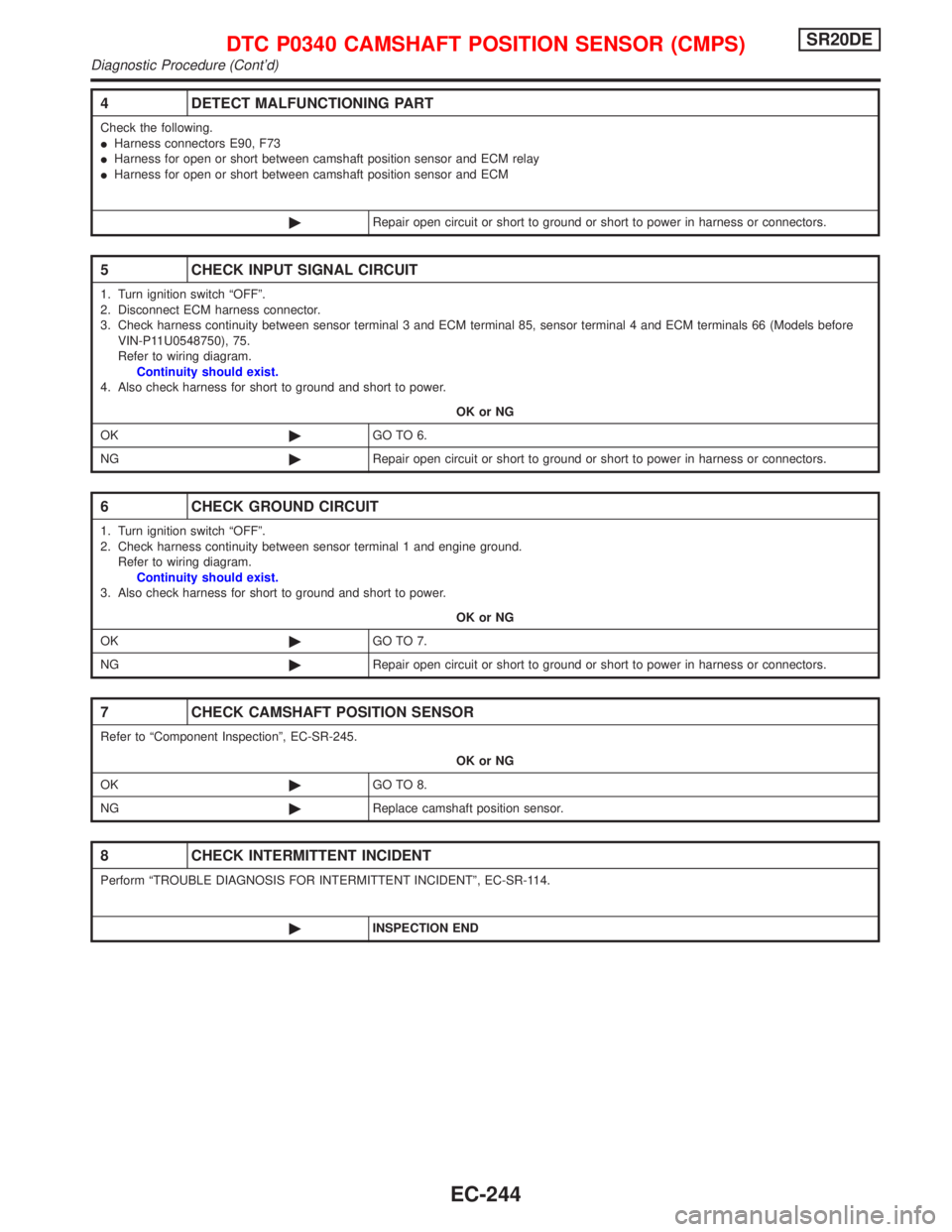
4 DETECT MALFUNCTIONING PART
Check the following.
IHarness connectors E90, F73
IHarness for open or short between camshaft position sensor and ECM relay
IHarness for open or short between camshaft position sensor and ECM
©Repair open circuit or short to ground or short to power in harness or connectors.
5 CHECK INPUT SIGNAL CIRCUIT
1. Turn ignition switch ªOFFº.
2. Disconnect ECM harness connector.
3. Check harness continuity between sensor terminal 3 and ECM terminal 85, sensor terminal 4 and ECM terminals 66 (Models before
VIN-P11U0548750), 75.
Refer to wiring diagram.
Continuity should exist.
4. Also check harness for short to ground and short to power.
OK or NG
OK©GO TO 6.
NG©Repair open circuit or short to ground or short to power in harness or connectors.
6 CHECK GROUND CIRCUIT
1. Turn ignition switch ªOFFº.
2. Check harness continuity between sensor terminal 1 and engine ground.
Refer to wiring diagram.
Continuity should exist.
3. Also check harness for short to ground and short to power.
OK or NG
OK©GO TO 7.
NG©Repair open circuit or short to ground or short to power in harness or connectors.
7 CHECK CAMSHAFT POSITION SENSOR
Refer to ªComponent Inspectionº, EC-SR-245.
OK or NG
OK©GO TO 8.
NG©Replace camshaft position sensor.
8 CHECK INTERMITTENT INCIDENT
Perform ªTROUBLE DIAGNOSIS FOR INTERMITTENT INCIDENTº, EC-SR-114.
©INSPECTION END
DTC P0340 CAMSHAFT POSITION SENSOR (CMPS)SR20DE
Diagnostic Procedure (Cont'd)
EC-244
Page 1048 of 2267
2 CHECK EXHAUST AIR LEAK
1. Start engine and run it at idle.
2. Listen for an exhaust air leak before the three way catalyst.
SEF099P
OK or NG
OK©GO TO 3.
NG©Repair or replace.
3 CHECK INTAKE AIR LEAK
Listen for an intake air leak after the mass air flow sensor.
OK or NG
OK©GO TO 4.
NG©Repair or replace.
4 CHECK IGNITION TIMING
Check for ignition timing.
Refer to TROUBLE DIAGNOSIS Ð ªBASIC INSPECTIONº, EC-SR-84.
OK or NG
OK©GO TO 5.
NG©Adjust ignition timing.
5 CHECK INJECTORS
1. Refer to Wiring Diagram for Injectors, EC-SR-304.
2. Stop engine and then turn ignition switch ªONº.
3. Check voltage between ECM terminals 101, 103, 105 and 107 and ground with CONSULT-II or tester.
SEF075XBattery voltage should exist.
OK or NG
OK©GO TO 6.
NG©Perform ªDiagnostic Procedureº INJECTOR, EC-SR-304.
DTC P0420 THREE WAY CATALYST FUNCTIONSR20DE
Diagnostic Procedure (Cont'd)
EC-248
Page 1052 of 2267
Wiring DiagramNCEC0253
YEC843
IGNITION SWITCH
ON or START
Refer to EL-POWER.: Detectable line for DTC
: Non-detectable line for DTC
: Hyper CVT models
: M/T models FUSE
BLOCK
(J/B)
EVAP
CANISTER
PURGE
CONTROL
SOLENOID
VA LV E
.ECM
REFER TO THE FOLLOWING
FUSE BLOCK -
Junction Box (J/B)
DTC P0443 EVAP CANISTER PURGE VOLUME CONTROL
SOLENOID VALVE (CIRCUIT)SR20DE
Wiring Diagram
EC-252
Page 1053 of 2267

Diagnostic ProcedureNCEC0254
1 CHECK POWER SUPPLY
1. Turn ignition switch ªOFFº.
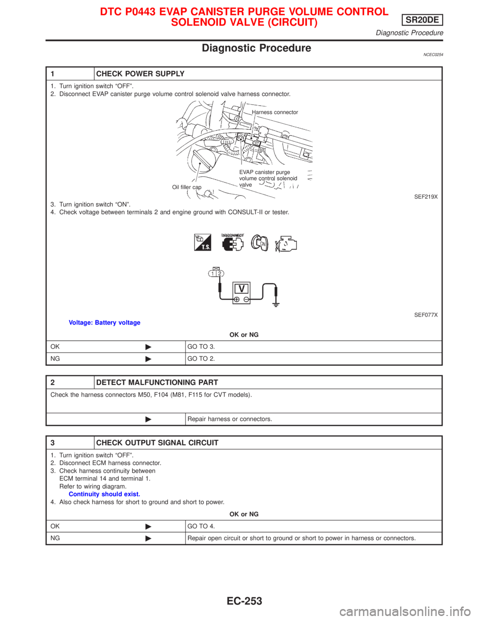
2. Disconnect EVAP canister purge volume control solenoid valve harness connector.
SEF219X3. Turn ignition switch ªONº.
4. Check voltage between terminals 2 and engine ground with CONSULT-II or tester.
SEF077XVoltage: Battery voltage
OK or NG
OK©GO TO 3.
NG©GO TO 2.
2 DETECT MALFUNCTIONING PART
Check the harness connectors M50, F104 (M81, F115 for CVT models).
©Repair harness or connectors.
3 CHECK OUTPUT SIGNAL CIRCUIT
1. Turn ignition switch ªOFFº.
2. Disconnect ECM harness connector.
3. Check harness continuity between
ECM terminal 14 and terminal 1.
Refer to wiring diagram.
Continuity should exist.
4. Also check harness for short to ground and short to power.
OK or NG
OK©GO TO 4.
NG©Repair open circuit or short to ground or short to power in harness or connectors.
Harness connector
EVAP canister purge
volume control solenoid
valve
Oil filler cap
DISCONNECT
DTC P0443 EVAP CANISTER PURGE VOLUME CONTROL
SOLENOID VALVE (CIRCUIT)SR20DE
Diagnostic Procedure
EC-253