1999 NISSAN PRIMERA engine
[x] Cancel search: enginePage 3 of 2267
AUTOMATIC TRANSAXLE
SECTION
AT(H×CVT)
CONTENTS
TROUBLE DIAGNOSIS - INDEX....................................3
Alphabetical & P No. Index for DTC ...........................3
PRECAUTIONS...............................................................5
Precautions for Supplemental Restraint System
(SRS)²AIR BAG²and²SEAT BELT
PRE-TENSIONER²......................................................5
Precautions for On Board Diagnostic (OBD)
System of CVT and Engine .........................................5
Precautions ..................................................................5
Service Notice or Precautions .....................................6
Wiring Diagrams and Trouble Diagnosis .....................7
PREPARATION...............................................................8
Special Service Tools ..................................................8
OVERALL SYSTEM........................................................9
CVT Electrical Parts Location......................................9
Circuit Diagram ..........................................................10
Cross-sectional View - RE0F06A .............................. 11
Control System ..........................................................12
ON BOARD DIAGNOSTIC SYSTEM
DESCRIPTION...............................................................15
Introduction ................................................................15
OBD Function for CVT System .................................15
OBD Diagnostic Trouble Code (DTC) .......................15
Malfunction Indicator (MI) ..........................................18
CONSULT-II ...............................................................18
TROUBLE DIAGNOSIS - INTRODUCTION..................29
Introduction ................................................................29
Work Flow ..................................................................32
TROUBLE DIAGNOSIS - BASIC INSPECTION...........34
CVT Fluid Check .......................................................34
Stall Test ....................................................................34
Line Pressure Test .....................................................35
Road Test...................................................................36
TROUBLE DIAGNOSIS - GENERAL
DESCRIPTION...............................................................41
TCM Terminals and Reference Value........................41TROUBLE DIAGNOSIS FOR POWER SUPPLY..........45
Wiring Diagram - CVT - MAIN...................................45
DTC P0705 PARK/NEUTRAL POSITION (PNP)
SWITCH.........................................................................48
Description .................................................................48
Wiring Diagram - AT - PNP/SW.................................50
Diagnostic Procedure ................................................51
Component Inspection ...............................................53
DTC P0710 CVT FLUID TEMPERATURE SENSOR
CIRCUIT.........................................................................54
Description .................................................................54
Wiring Diagram - AT - FTS ........................................56
Diagnostic Procedure ................................................57
DTC P0715 PRIMARY SPEED SENSOR.....................59
Description .................................................................59
Wiring Diagram - AT - VSSA/T ..................................60
Diagnostic Procedure ................................................61
Component Inspection ...............................................61
DTC P0720 VEHICLE SPEED SENSOR CVT
(SECONDARY SPEED SENSOR)................................62
Description .................................................................62
Wiring Diagram - AT - VSSA/T ..................................64
Diagnostic Procedure ................................................65
Component Inspection ...............................................65
DTC P0725 ENGINE SPEED SIGNAL.........................66
Description .................................................................66
Wiring Diagram - AT - ENGSS ..................................67
Diagnostic Procedure ................................................68
DTC P0740 TORQUE CONVERTER CLUTCH
SOLENOID VALVE........................................................69
Description .................................................................69
Wiring Diagram - AT - TCV........................................71
Diagnostic Procedure ................................................72
Component Inspection ...............................................73
DTC P0745 LINE PRESSURE SOLENOID VALVE.....74
Description .................................................................74
AT
Page 7 of 2267
Precautions for Supplemental Restraint System
(SRS) ªAIR BAGº and ªSEAT BELT
PRE-TENSIONERº
NCAT0002The Supplemental Restraint System ªAIR BAGº and ªSEAT BELT PRE-TENSIONERº, used along with a seat
belt, help to reduce the risk or severity of injury to the driver and front passenger in a frontal collision. The
Supplemental Restraint System consists of air bag modules (located in the center of the steering wheel and
on the instrument panel on the passenger side), seat belt pre-tensioners, a diagnosis sensor unit, warning
lamp, wiring harness and spiral cable.
In addition to the supplemental air bag modules for a frontal collision, the supplemental side air bag used along
with the seat belt helps to reduce the risk or severity of injury to the driver and front passenger in a side col-
lision. The supplemental side air bag consists of air bag modules (located in the outer side of front seats),
satellite sensor, diagnosis sensor unit (one of components of supplemental air bags for a frontal collision),
wiring harness, warning lamp (one of components of supplemental air bags for a frontal collision). Information
necessary to service the system safely is included in theRS sectionof this Service Manual.
WARNING:
ITo avoid rendering the SRS inoperative, which could increase the risk of personal injury or death
in the event of a collision which would result in air bag inflation, all maintenance must be performed
by an authorized NISSAN dealer.
IImproper maintenance, including incorrect removal and installation of the SRS, can lead to per-
sonal injury caused by unintentional activation of the system.
IDo not use electrical test equipment on any circuit related to the SRS unless instructed to in this
Service Manual. SRS wiring harnesses (except ªSEAT BELT PRE-TENSIONERº connector) can be
identified with yellow harness connector (and with yellow harness protector or yellow insulation
tape before the harness connectors).
Precautions for On Board Diagnostic (OBD)
System of CVT and Engine
NCAT0198The ECM has an on board diagnostic system. It will light up the malfunction indicator (MI) to warn the driver
of a malfunction causing emission deterioration.
CAUTION:
IBe sure to turn the ignition switch ªOFFº and disconnect the negative battery terminal before any
repair or inspection work. The open/short circuit of related switches, sensors, solenoid valves, etc.
will cause the MI to light up.
IBe sure to connect and lock the connectors securely after work. A loose (unlocked) connector will
cause the MI to light up due to an open circuit. (Be sure the connector is free from water, grease,
dirt, bent terminals, etc.)
IBe sure to route and secure the harnesses properly after work. Interference of the harness with a
bracket, etc. may cause the MI to light up due to a short circuit.
IBe sure to connect rubber tubes properly after work. A misconnected or disconnected rubber tube
may cause the MI to light up due to a malfunction of the EGR system or fuel injection system, etc.
IBe sure to erase the unnecessary malfunction information (repairs completed) from the TCM and
ECM before returning the vehicle to the customer.
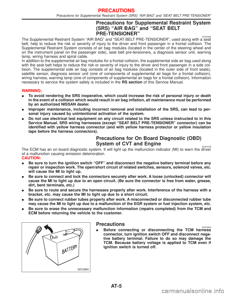
PrecautionsNCAT0003IBefore connecting or disconnecting the TCM harness
connector, turn ignition switch OFF and disconnect nega-
tive battery terminal. Failure to do so may damage the
TCM. Because battery voltage is applied to TCM even if
ignition switch is turned off.
SEF289H
PRECAUTIONS
Precautions for Supplemental Restraint System (SRS) ªAIR BAGº and ªSEAT BELT PRE-TENSIONERº
AT-5
Page 14 of 2267
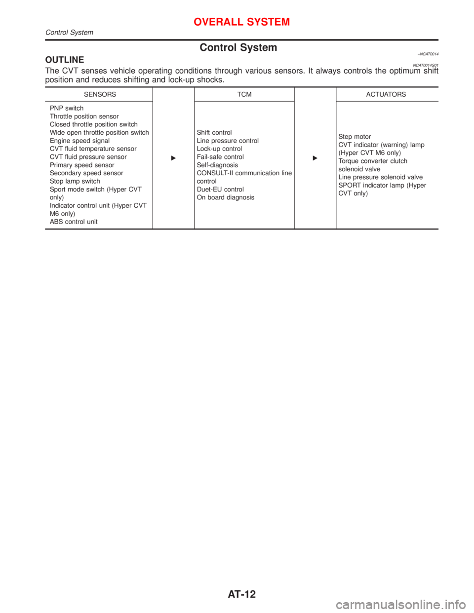
Control System=NCAT0014OUTLINENCAT0014S01The CVT senses vehicle operating conditions through various sensors. It always controls the optimum shift
position and reduces shifting and lock-up shocks.
SENSORS
ETCM
EACTUATORS
PNP switch
Throttle position sensor
Closed throttle position switch
Wide open throttle position switch
Engine speed signal
CVT fluid temperature sensor
CVT fluid pressure sensor
Primary speed sensor
Secondary speed sensor
Stop lamp switch
Sport mode switch (Hyper CVT
only)
Indicator control unit (Hyper CVT
M6 only)
ABS control unitShift control
Line pressure control
Lock-up control
Fail-safe control
Self-diagnosis
CONSULT-II communication line
control
Duet-EU control
On board diagnosisStep motor
CVT indicator (warning) lamp
(Hyper CVT M6 only)
Torque converter clutch
solenoid valve
Line pressure solenoid valve
SPORT indicator lamp (Hyper
CVT only)
OVERALL SYSTEM
Control System
AT-12
Page 15 of 2267
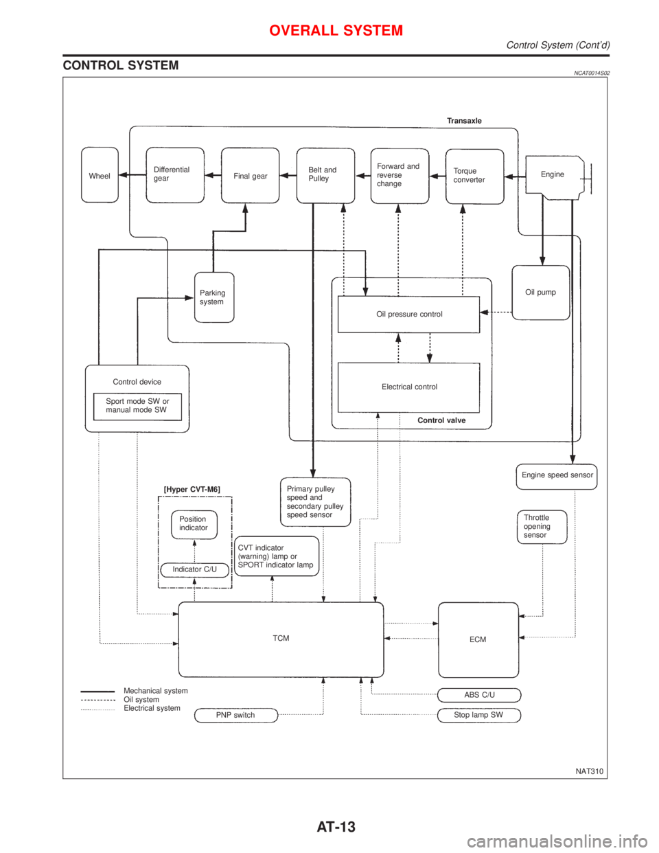
CONTROL SYSTEMNCAT0014S02
NAT310 WheelDifferential
gearFinal gearBelt and
PulleyForward and
reverse
changeTorque
converterEngine Transaxle
Oil pump
Oil pressure control Parking
system
Control device
Sport mode SW or
manual mode SWElectrical control
Control valve
Primary pulley
speed and
secondary pulley
speed sensor
CVT indicator
(warning) lamp or
SPORT indicator lamp [Hyper CVT-M6]
Position
indicator
Indicator C/U
TCM
Mechanical system
Oil system
Electrical system
Stop lamp SWABS C/UECMThrottle
opening
sensor Engine speed sensor
PNP switch
OVERALL SYSTEM
Control System (Cont'd)
AT-13
Page 16 of 2267
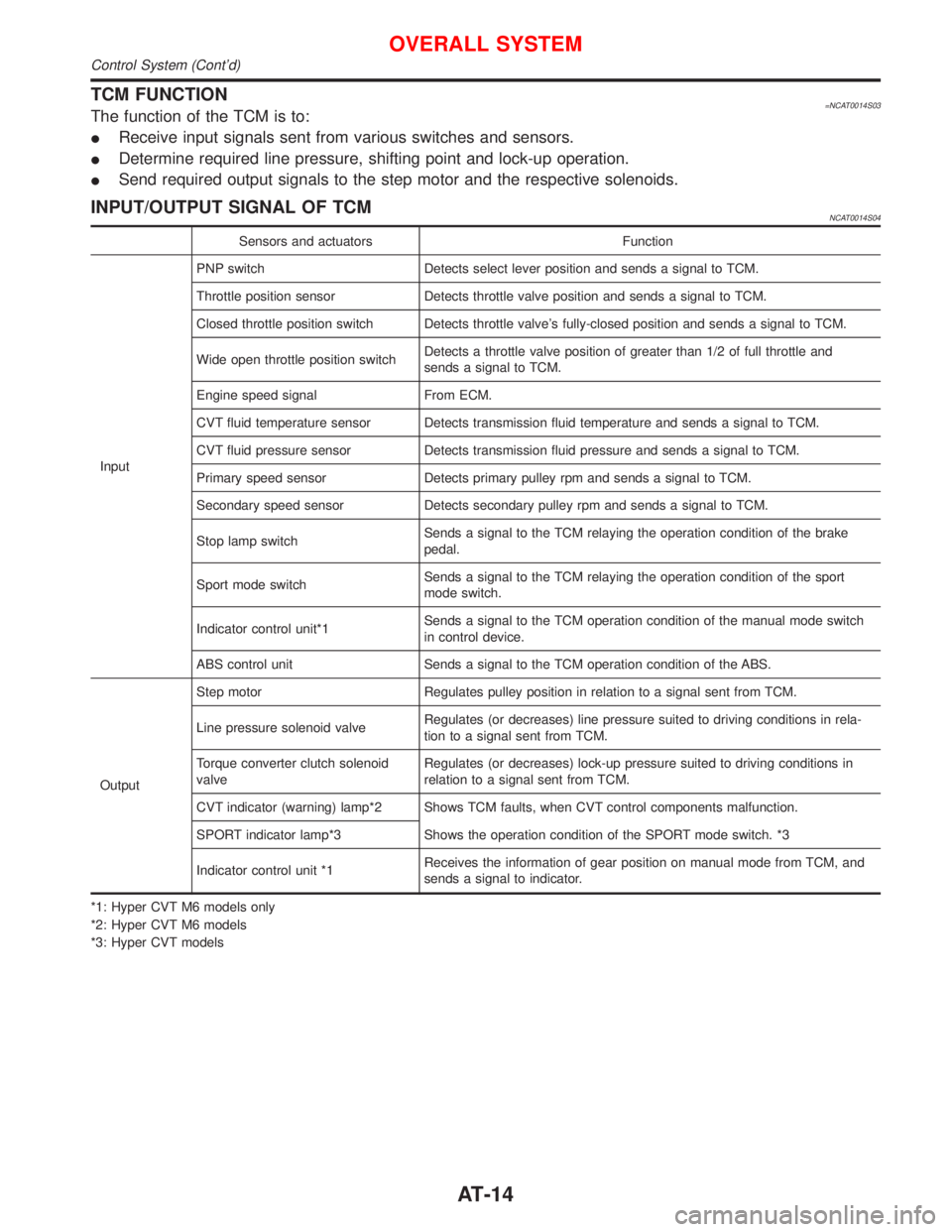
TCM FUNCTION=NCAT0014S03The function of the TCM is to:
IReceive input signals sent from various switches and sensors.
IDetermine required line pressure, shifting point and lock-up operation.
ISend required output signals to the step motor and the respective solenoids.
INPUT/OUTPUT SIGNAL OF TCMNCAT0014S04
Sensors and actuators Function
InputPNP switch Detects select lever position and sends a signal to TCM.
Throttle position sensor Detects throttle valve position and sends a signal to TCM.
Closed throttle position switch Detects throttle valve's fully-closed position and sends a signal to TCM.
Wide open throttle position switchDetects a throttle valve position of greater than 1/2 of full throttle and
sends a signal to TCM.
Engine speed signal From ECM.
CVT fluid temperature sensor Detects transmission fluid temperature and sends a signal to TCM.
CVT fluid pressure sensor Detects transmission fluid pressure and sends a signal to TCM.
Primary speed sensor Detects primary pulley rpm and sends a signal to TCM.
Secondary speed sensor Detects secondary pulley rpm and sends a signal to TCM.
Stop lamp switchSends a signal to the TCM relaying the operation condition of the brake
pedal.
Sport mode switchSends a signal to the TCM relaying the operation condition of the sport
mode switch.
Indicator control unit*1Sends a signal to the TCM operation condition of the manual mode switch
in control device.
ABS control unit Sends a signal to the TCM operation condition of the ABS.
OutputStep motor Regulates pulley position in relation to a signal sent from TCM.
Line pressure solenoid valveRegulates (or decreases) line pressure suited to driving conditions in rela-
tion to a signal sent from TCM.
Torque converter clutch solenoid
valveRegulates (or decreases) lock-up pressure suited to driving conditions in
relation to a signal sent from TCM.
CVT indicator (warning) lamp*2 Shows TCM faults, when CVT control components malfunction.
SPORT indicator lamp*3 Shows the operation condition of the SPORT mode switch. *3
Indicator control unit *1Receives the information of gear position on manual mode from TCM, and
sends a signal to indicator.
*1: Hyper CVT M6 models only
*2: Hyper CVT M6 models
*3: Hyper CVT models
OVERALL SYSTEM
Control System (Cont'd)
AT-14
Page 17 of 2267
IntroductionNCAT0017The CVT system has two self-diagnostic systems.
The first is the emission-related on board diagnostic system (OBD) performed by the TCM in combination with
the ECM. The malfunction is indicated by the MI (malfunction indicator) and is stored as a DTC in the ECM
memory but not the TCM memory.
The second is the TCM original self-diagnosis indicated by the CVT indicator (warning) lamp or SPORT indi-
cator lamp. The malfunction is stored in the TCM memory. The detected items are overlapped with OBD self-
diagnostic items. For detail, refer to AT-26.
OBD Function for CVT SystemNCAT0018The ECM provides emission-related on board diagnostic (OBD) functions for the CVT system. One function
is to receive a signal from the TCM used with OBD-related parts of the CVT system. The signal is sent to the
ECM when a malfunction occurs in the corresponding OBD-related part. The other function is to indicate a
diagnostic result by means of the MI (malfunction indicator) on the instrument panel. Sensors, switches and
solenoid valves are used as sensing elements.
The MI automatically illuminates in Two Trip Detection Logic when a malfunction is sensed in relation to CVT
system parts.
OBD Diagnostic Trouble Code (DTC)NCAT0020HOW TO READ DTC AND 1ST TRIP DTCNCAT0020S01DTC and 1st trip DTC can be read by the following methods.
1.(
No Tools)The number of blinks of the malfunction indicator in the Diagnostic Test Mode II (Self-Di-
agnostic Results) Examples: 0705, 0710, 0715, 0720, etc. For details, refer to EC section [ªMalfunction
Indicator (MI)º, ªON BOARD DIAGNOSTIC SYSTEM DESCRIPTIONº].
These DTCs are controlled by NISSAN.
2.(
with CONSULT-II orGST)CONSULT-II or GST (Generic Scan Tool) Examples: P0705, P0710,
P0720, P0725, etc.
These DTCs are prescribed by ISO15031-6.
(CONSULT-II also displays the malfunctioning component or system.)
I1st trip DTC No. is the same as DTC No.
IOutput of the diagnostic trouble code indicates that the indicated circuit has a malfunction.
However, in case of the Mode II and GST they do not indicate whether the malfunction is still
occurring or occurred in the past and returned to normal.
CONSULT-II can identify them as shown below. Therefore, using CONSULT-II (if available) is rec-
ommended.
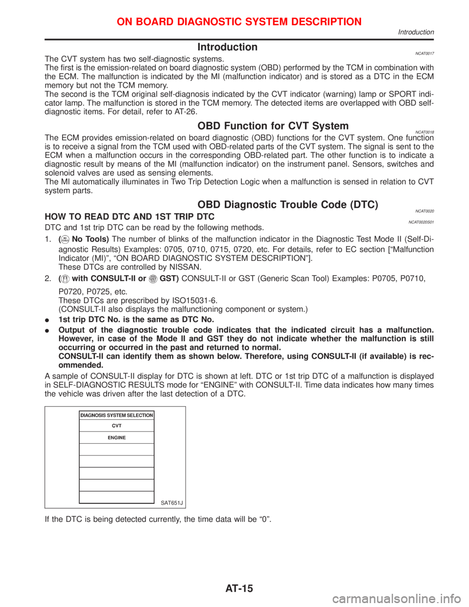
A sample of CONSULT-II display for DTC is shown at left. DTC or 1st trip DTC of a malfunction is displayed
in SELF-DIAGNOSTIC RESULTS mode for ªENGINEº with CONSULT-II. Time data indicates how many times
the vehicle was driven after the last detection of a DTC.
If the DTC is being detected currently, the time data will be ª0º.
SAT651J
ON BOARD DIAGNOSTIC SYSTEM DESCRIPTION
Introduction
AT-15
Page 18 of 2267
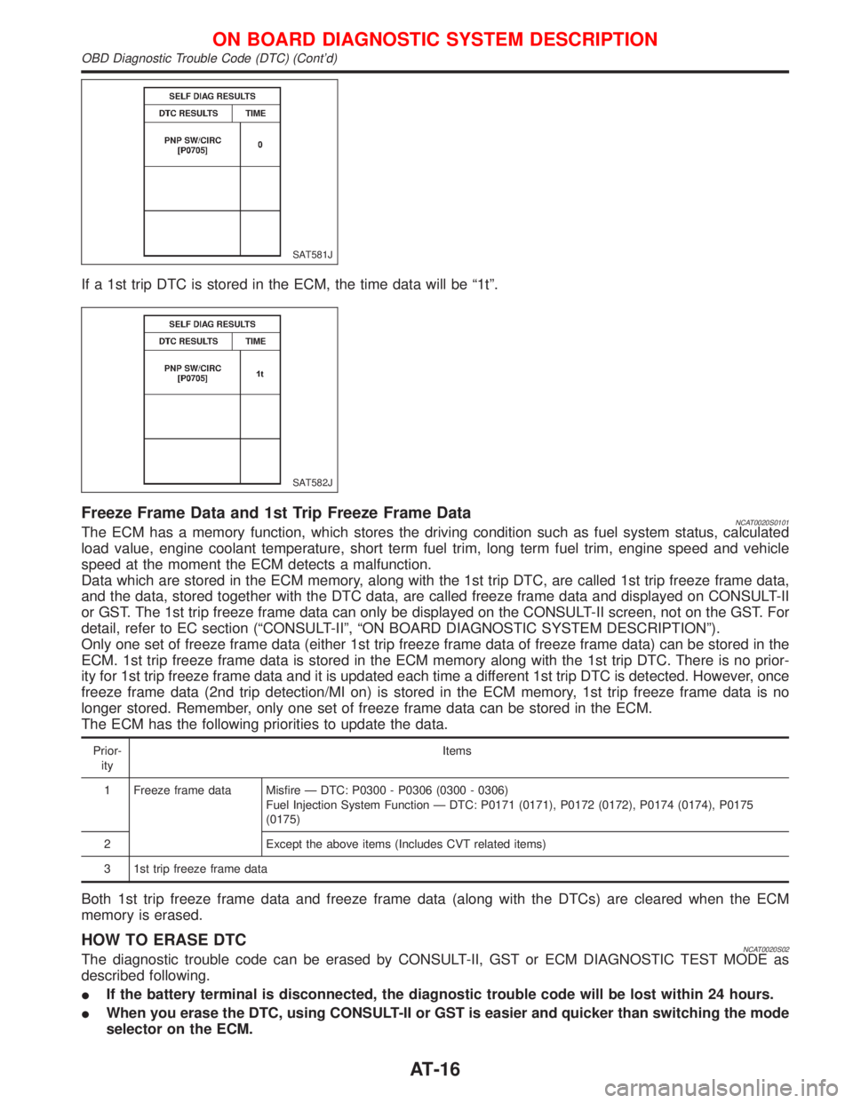
If a 1st trip DTC is stored in the ECM, the time data will be ª1tº.
Freeze Frame Data and 1st Trip Freeze Frame DataNCAT0020S0101The ECM has a memory function, which stores the driving condition such as fuel system status, calculated
load value, engine coolant temperature, short term fuel trim, long term fuel trim, engine speed and vehicle
speed at the moment the ECM detects a malfunction.
Data which are stored in the ECM memory, along with the 1st trip DTC, are called 1st trip freeze frame data,
and the data, stored together with the DTC data, are called freeze frame data and displayed on CONSULT-II
or GST. The 1st trip freeze frame data can only be displayed on the CONSULT-II screen, not on the GST. For
detail, refer to EC section (ªCONSULT-IIº, ªON BOARD DIAGNOSTIC SYSTEM DESCRIPTIONº).
Only one set of freeze frame data (either 1st trip freeze frame data of freeze frame data) can be stored in the
ECM. 1st trip freeze frame data is stored in the ECM memory along with the 1st trip DTC. There is no prior-
ity for 1st trip freeze frame data and it is updated each time a different 1st trip DTC is detected. However, once
freeze frame data (2nd trip detection/MI on) is stored in the ECM memory, 1st trip freeze frame data is no
longer stored. Remember, only one set of freeze frame data can be stored in the ECM.
The ECM has the following priorities to update the data.
Prior-
ityItems
1 Freeze frame data Misfire Ð DTC: P0300 - P0306 (0300 - 0306)
Fuel Injection System Function Ð DTC: P0171 (0171), P0172 (0172), P0174 (0174), P0175
(0175)
2 Except the above items (Includes CVT related items)
3 1st trip freeze frame data
Both 1st trip freeze frame data and freeze frame data (along with the DTCs) are cleared when the ECM
memory is erased.
HOW TO ERASE DTCNCAT0020S02The diagnostic trouble code can be erased by CONSULT-II, GST or ECM DIAGNOSTIC TEST MODE as
described following.
IIf the battery terminal is disconnected, the diagnostic trouble code will be lost within 24 hours.
IWhen you erase the DTC, using CONSULT-II or GST is easier and quicker than switching the mode
selector on the ECM.
SAT581J
SAT582J
ON BOARD DIAGNOSTIC SYSTEM DESCRIPTION
OBD Diagnostic Trouble Code (DTC) (Cont'd)
AT-16
Page 19 of 2267
The following emission-related diagnostic information is cleared from the ECM memory when erasing DTC
related to OBD. For details, refer to EC section (ªEmission-related Diagnostic Informationº, ªON BOARD
DIAGNOSTIC SYSTEM DESCRIPTIONº).
IDiagnostic trouble codes (DTC)
I1st trip diagnostic trouble codes (1st trip DTC)
IFreeze frame data
I1st trip freeze frame data
ISystem readiness test (SRT) codes
ITest values
IDistance traveled while MI is activated
IOthers
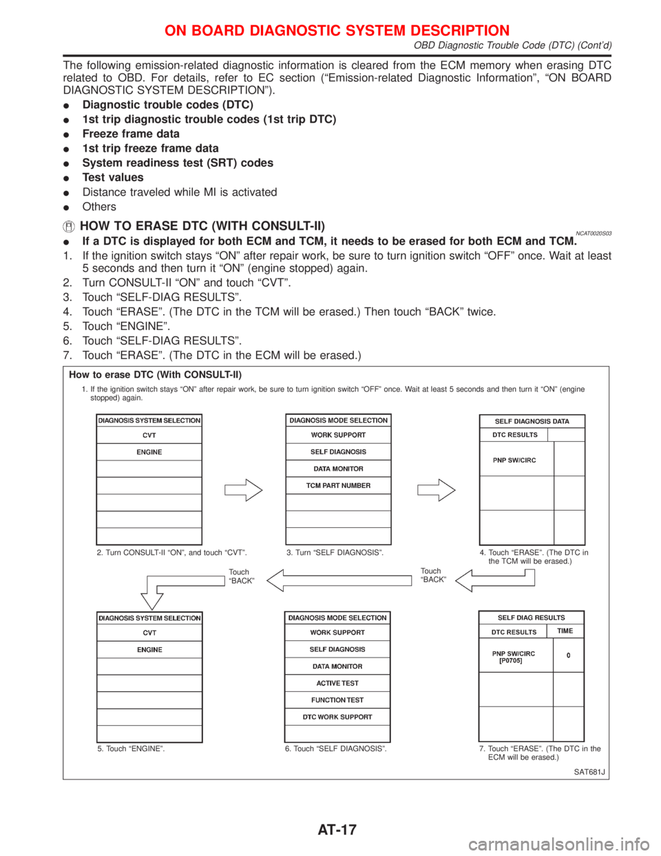
HOW TO ERASE DTC (WITH CONSULT-II)NCAT0020S03IIf a DTC is displayed for both ECM and TCM, it needs to be erased for both ECM and TCM.
1. If the ignition switch stays ªONº after repair work, be sure to turn ignition switch ªOFFº once. Wait at least
5 seconds and then turn it ªONº (engine stopped) again.
2. Turn CONSULT-II ªONº and touch ªCVTº.
3. Touch ªSELF-DIAG RESULTSº.
4. Touch ªERASEº. (The DTC in the TCM will be erased.) Then touch ªBACKº twice.
5. Touch ªENGINEº.
6. Touch ªSELF-DIAG RESULTSº.
7. Touch ªERASEº. (The DTC in the ECM will be erased.)
SAT681J
How to erase DTC (With CONSULT-II)
1. If the ignition switch stays ªONº after repair work, be sure to turn ignition switch ªOFFº once. Wait at least 5 seconds and then turn it ªONº (engine
stopped) again.
2. Turn CONSULT-II ªONº, and touch ªCVTº. 3. Turn ªSELF DIAGNOSISº. 4. Touch ªERASEº. (The DTC in
the TCM will be erased.)
Touch
ªBACKºTouch
ªBACKº
5. Touch ªENGINEº. 6. Touch ªSELF DIAGNOSISº. 7. Touch ªERASEº. (The DTC in the
ECM will be erased.)
.
.
ON BOARD DIAGNOSTIC SYSTEM DESCRIPTION
OBD Diagnostic Trouble Code (DTC) (Cont'd)
AT-17