Page 925 of 2267

6 CHECK POWER SUPPLY-II
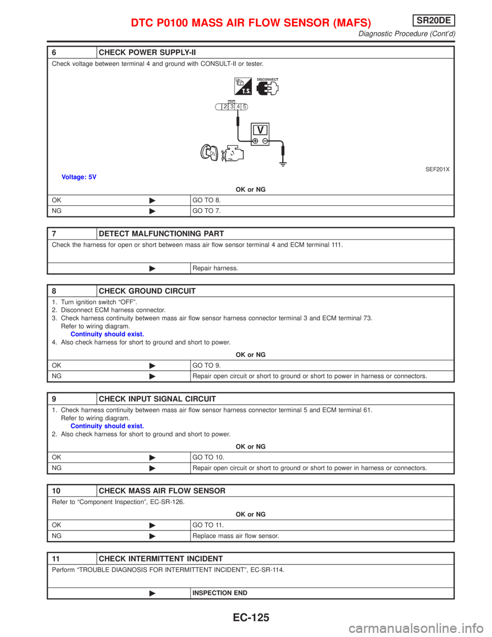
Check voltage between terminal 4 and ground with CONSULT-II or tester.
SEF201XVoltage: 5V
OK or NG
OK©GO TO 8.
NG©GO TO 7.
7 DETECT MALFUNCTIONING PART
Check the harness for open or short between mass air flow sensor terminal 4 and ECM terminal 111.
©Repair harness.
8 CHECK GROUND CIRCUIT
1. Turn ignition switch ªOFFº.
2. Disconnect ECM harness connector.
3. Check harness continuity between mass air flow sensor harness connector terminal 3 and ECM terminal 73.
Refer to wiring diagram.
Continuity should exist.
4. Also check harness for short to ground and short to power.
OK or NG
OK©GO TO 9.
NG©Repair open circuit or short to ground or short to power in harness or connectors.
9 CHECK INPUT SIGNAL CIRCUIT
1. Check harness continuity between mass air flow sensor harness connector terminal 5 and ECM terminal 61.
Refer to wiring diagram.
Continuity should exist.
2. Also check harness for short to ground and short to power.
OK or NG
OK©GO TO 10.
NG©Repair open circuit or short to ground or short to power in harness or connectors.
10 CHECK MASS AIR FLOW SENSOR
Refer to ªComponent Inspectionº, EC-SR-126.
OK or NG
OK©GO TO 11.
NG©Replace mass air flow sensor.
11 CHECK INTERMITTENT INCIDENT
Perform ªTROUBLE DIAGNOSIS FOR INTERMITTENT INCIDENTº, EC-SR-114.
©INSPECTION END
DTC P0100 MASS AIR FLOW SENSOR (MAFS)SR20DE
Diagnostic Procedure (Cont'd)
EC-125
Page 928 of 2267
Wiring DiagramNCEC0069
YEC830
INTAKE AIR
TEMPERATURE
SENSOR: Detectable line for DTC
: Non-detectable line for DTC
: Hyper CVT models
ECM
DTC P0110 INTAKE AIR TEMPERATURE SENSORSR20DE
Wiring Diagram
EC-128
Page 930 of 2267
3 CHECK GROUND CIRCUIT
1. Turn ignition switch ªOFFº.
2. Check harness continuity between intake air temperature sensor (mass air flow sensor) harness connector terminal 3 and ECM termi-
nal 73.
Refer to wiring diagram.
Continuity should exist.
3. Also check harness for short to ground and short to power.
OK or NG
OK©GO TO 5.
NG©GO TO 4.
4 DETECT MALFUNCTIONING PART
Check the following.
IHarness for open or short between ECM and intake air temperature sensor
©Repair open circuit or short to ground or short to power in harness or connectors.
5 CHECK INTAKE AIR TEMPERATURE SENSOR
Refer to ªComponent Inspectionº, EC-SR-131.
OK or NG
OK©GO TO 6.
NG©Replace mass air flow sensor.
6 CHECK INTERMITTENT INCIDENT
Perform ªTROUBLE DIAGNOSIS FOR INTERMITTENT INCIDENTº, EC-SR-114.
©INSPECTION END
DTC P0110 INTAKE AIR TEMPERATURE SENSORSR20DE
Diagnostic Procedure (Cont'd)
EC-130
Page 934 of 2267
Wiring DiagramNCEC0076
YEC082A
DTC P0115 ENGINE COOLANT TEMPERATURE SENSOR
(ECTS) (CIRCUIT)SR20DE
Wiring Diagram
EC-134
Page 935 of 2267
Diagnostic ProcedureNCEC0077
1 CHECK POWER SUPPLY
1. Turn ignition switch ªOFFº.
2. Disconnect engine coolant temperature sensor harness connector.
SEF205X3. Turn ignition switch ªONº.
4. Check voltage between terminal 2 and ground with CONSULT-II or tester.
SEF997WVoltage: Approximately 5V
OK or NG
OK©GO TO 3.
NG©GO TO 2.
2 DETECT MALFUNCTIONING PART
Check the harness for open or short between ECM and engine coolant temperature sensor.
©Repair harness or connectors.
3 CHECK GROUND CIRCUIT
1. Turn ignition switch ªOFFº.
2. Check harness continuity between engine coolant temperature sensor harness connector terminal 1 and engine ground.
Refer to wiring diagram.
Continuity should exist.
3. Also check harness for short to ground and short to power.
OK or NG
OK©GO TO 5.
NG©GO TO 4.
Front exhaust tube
FrontCoolant temperature
sensor harness
connector
DTC P0115 ENGINE COOLANT TEMPERATURE SENSOR
(ECTS) (CIRCUIT)SR20DE
Diagnostic Procedure
EC-135
Page 940 of 2267
Wiring DiagramNCEC0084
YEC083A
DTC P0120 THROTTLE POSITION SENSORSR20DE
Wiring Diagram
EC-140
Page 941 of 2267
Diagnostic ProcedureNCEC0085
1 RETIGHTEN GROUND SCREWS
1. Turn ignition switch ªOFFº.
2. Loosen and retighten engine ground screws.
SEF202X
©GO TO 2.
2 CHECK POWER SUPPLY
1. Disconnect throttle position sensor harness connector.
SEF197X2. Turn ignition switch ªONº.
3. Check voltage between terminal 3 and ground with CONSULT-II or tester.
SEF209WVoltage: Approximately 5V
OK or NG
OK©GO TO 3.
NG©Repair harness or connectors.
3 CHECK GROUND CIRCUIT
1. Turn ignition switch ªOFFº.
2. Check harness continuity between throttle position sensor harness connector terminal 1 and engine ground.
Refer to wiring diagram.
Continuity should exist.
3. Also check harness for short to ground and short to power.
OK or NG
OK©GO TO 5.
NG©GO TO 4.
Intake manifold
collector
Engine
ground
Throttle position
sensor harness
connector Throttle body
Closed throttle position switch
harness connector (CVT
models)
DTC P0120 THROTTLE POSITION SENSORSR20DE
Diagnostic Procedure
EC-141
Page 942 of 2267

Component InspectionNCEC0086THROTTLE POSITION SENSORNCEC0086S01With CONSULT-II
1) Start engine and warm it up to normal operating temperature.
2) Stop engine (ignition switch OFF).
3) Turn ignition switch ON.
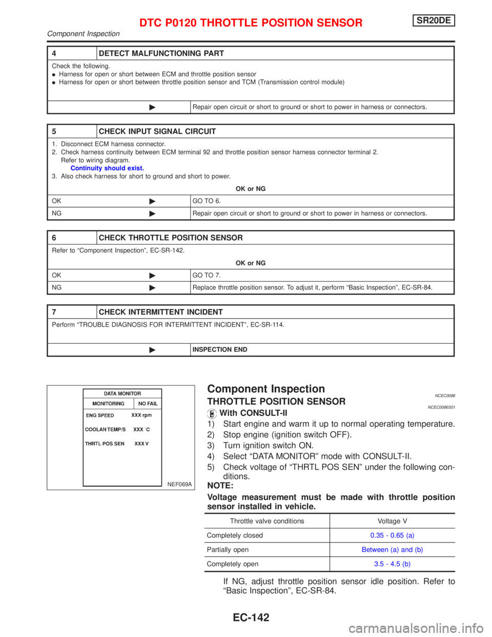
4) Select ªDATA MONITORº mode with CONSULT-II.
5) Check voltage of ªTHRTL POS SENº under the following con-
ditions.
NOTE:
Voltage measurement must be made with throttle position
sensor installed in vehicle.
Throttle valve conditions Voltage V
Completely closed0.35 - 0.65 (a)
Partially openBetween (a) and (b)
Completely open3.5 - 4.5 (b)
If NG, adjust throttle position sensor idle position. Refer to
ªBasic Inspectionº, EC-SR-84.
4 DETECT MALFUNCTIONING PART
Check the following.
IHarness for open or short between ECM and throttle position sensor
IHarness for open or short between throttle position sensor and TCM (Transmission control module)
©Repair open circuit or short to ground or short to power in harness or connectors.
5 CHECK INPUT SIGNAL CIRCUIT
1. Disconnect ECM harness connector.
2. Check harness continuity between ECM terminal 92 and throttle position sensor harness connector terminal 2.
Refer to wiring diagram.
Continuity should exist.
3. Also check harness for short to ground and short to power.
OK or NG
OK©GO TO 6.
NG©Repair open circuit or short to ground or short to power in harness or connectors.
6 CHECK THROTTLE POSITION SENSOR
Refer to ªComponent Inspectionº, EC-SR-142.
OK or NG
OK©GO TO 7.
NG©Replace throttle position sensor. To adjust it, perform ªBasic Inspectionº, EC-SR-84.
7 CHECK INTERMITTENT INCIDENT
Perform ªTROUBLE DIAGNOSIS FOR INTERMITTENT INCIDENTº, EC-SR-114.
©INSPECTION END
NEF069A
DTC P0120 THROTTLE POSITION SENSORSR20DE
Component Inspection
EC-142