DIAGNOSTIC PROCEDURE 2
(Security indicator check)
CHECK INDICATOR LAMP OUTPUT
SIGNAL.
1) Remove time control unit from fuse
block.
Note: Fuse block (J/B) is very
fragile. TCU should be removed
carefully to avoid breaking the
locking bars.
2) Check voltage between control unit
terminal
�18and ground.
Battery voltage should exist.
Refer to wiring diagram EL-316.
NG
�OK
Security indicator lamp is
OK.
Security
indicator on
dashboardSecurity indica-
tor built-in com-
bination meter��A
CHECK INDICATOR LAMP.
OK
�NG
Replace indicator lamp.
CHECK POWER SUPPLY CIRCUIT
FOR INDICATOR.
1) Disconnect security indicator con-
nector.
2) Check voltage between indicator
terminal
�2and ground.
Battery voltage should exist.
OK
�NG
Check the following:
�10A fuse [No.16 ,
located in the fuse
block (J/B)]
�Harness for open or
short between security
indicator lamp and
fuse
Check harness for open or short
between security indicator and control
unit.
�A
CHECK INDICATOR LAMP.
OK
�NG
Replace combination
meter.
CHECK POWER SUPPLY CIRCUIT
FOR INDICATOR.
1) Disconnect combination meter con-
nector.
2) Check voltage between indicator
terminal
�23and ground.
Battery voltage should exist.
OK
�NG
Check the following:
�10A fuse [No.16 ,
located in the fuse
block (J/B)]
�Harness for open or
short between combi-
nation meter and fuse
Check harness for open or short
between combination meter and con-
trol unit.
YEL461B Time control
unit connector
YEL462B Security indicator
connector
YEL037D
�
�
�
�
�
�
THEFT WARNING SYSTEM
Trouble Diagnoses (Cont’d)
EL-336
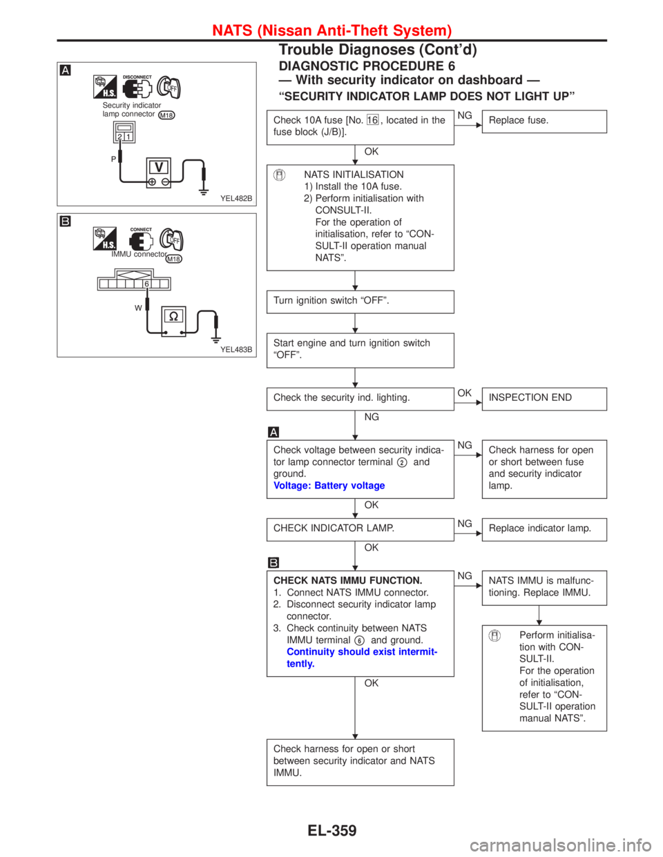
DIAGNOSTIC PROCEDURE 6
—With security indicator on dashboard—
“SECURITY INDICATOR LAMP DOES NOT LIGHT UP”
Check 10A fuse [No.16 , located in the
fuse block (J/B)].
OK
�NG
Replace fuse.
NATS INITIALISATION
1) Install the 10A fuse.
2) Perform initialisation with
CONSULT-II.
For the operation of
initialisation, refer to“CON-
SULT-II operation manual
NATS”.
Turn ignition switch“OFF”.
Start engine and turn ignition switch
“OFF”.
Check the security ind. lighting.
NG
�OK
INSPECTION END
Check voltage between security indica-
tor lamp connector terminal
�2and
ground.
Voltage: Battery voltage
OK
�NG
Check harness for open
or short between fuse
and security indicator
lamp.
CHECK INDICATOR LAMP.
OK
�NG
Replace indicator lamp.
CHECK NATS IMMU FUNCTION.
1. Connect NATS IMMU connector.
2. Disconnect security indicator lamp
connector.
3. Check continuity between NATS
IMMU terminal
�6and ground.
Continuity should exist intermit-
tently.
OK
�NG
NATS IMMU is malfunc-
tioning. Replace IMMU.
Perform initialisa-
tion with CON-
SULT-II.
For the operation
of initialisation,
refer to“CON-
SULT-II operation
manual NATS”.
Check harness for open or short
between security indicator and NATS
IMMU.
YEL482B
Security indicator
lamp connector
YEL483B
IMMU connector
�
�
�
�
�
�
�
�
�
NATS (Nissan Anti-Theft System)
Trouble Diagnoses (Cont’d)
EL-359

CHECK INDICATOR LAMP OUTPUT
SIGNAL.
1) Remove time control unit from fuse
block.
Note: Fuse block (J/B) is very
fragile. TCU should be removed
careful")