1999 NISSAN PRIMERA checking oil
[x] Cancel search: checking oilPage 36 of 2267
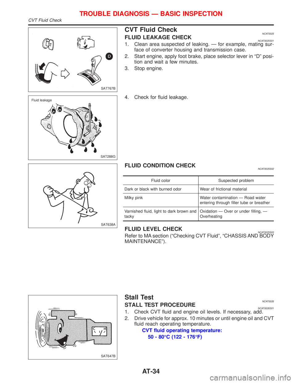
CVT Fluid CheckNCAT0025FLUID LEAKAGE CHECKNCAT0025S011. Clean area suspected of leaking. Ð for example, mating sur-
face of converter housing and transmission case.
2. Start engine, apply foot brake, place selector lever in ªDº posi-
tion and wait a few minutes.
3. Stop engine.
4. Check for fluid leakage.
FLUID CONDITION CHECKNCAT0025S02
Fluid color Suspected problem
Dark or black with burned odor Wear of frictional material
Milky pink Water contamination Ð Road water
entering through filler tube or breather
Varnished fluid, light to dark brown and
tackyOxidation Ð Over or under filling, Ð
Overheating
FLUID LEVEL CHECKNCAT0025S03Refer to MA section (ªChecking CVT Fluidº, ªCHASSIS AND BODY
MAINTENANCEº).
Stall TestNCAT0026STALL TEST PROCEDURENCAT0026S011. Check CVT fluid and engine oil levels. If necessary, add.
2. Drive vehicle for approx. 10 minutes or until engine oil and CVT
fluid reach operating temperature.
CVT fluid operating temperature:
50 - 80ÉC (122 - 176ÉF)
SAT767B
SAT288G Fluid leakage
SAT638A
SAT647B
TROUBLE DIAGNOSIS Ð BASIC INSPECTION
CVT Fluid Check
AT-34
Page 129 of 2267
Checking Brake Fluid Level
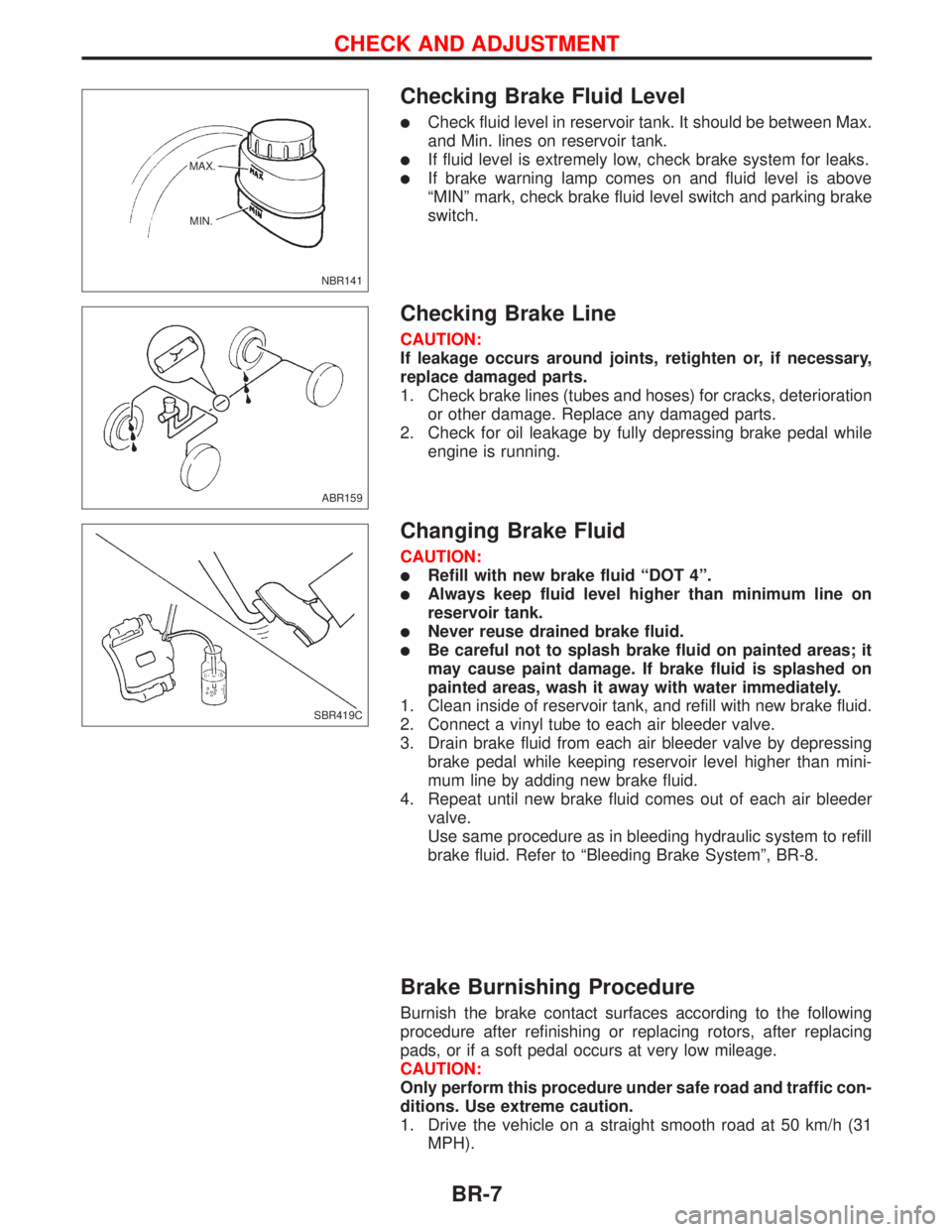
lCheck fluid level in reservoir tank. It should be between Max.
and Min. lines on reservoir tank.
lIf fluid level is extremely low, check brake system for leaks.
lIf brake warning lamp comes on and fluid level is above
ªMINº mark, check brake fluid level switch and parking brake
switch.
Checking Brake Line
CAUTION:
If leakage occurs around joints, retighten or, if necessary,
replace damaged parts.
1. Check brake lines (tubes and hoses) for cracks, deterioration
or other damage. Replace any damaged parts.
2. Check for oil leakage by fully depressing brake pedal while
engine is running.
Changing Brake Fluid
CAUTION:
lRefill with new brake fluid ªDOT 4º.
lAlways keep fluid level higher than minimum line on
reservoir tank.
lNever reuse drained brake fluid.
lBe careful not to splash brake fluid on painted areas; it
may cause paint damage. If brake fluid is splashed on
painted areas, wash it away with water immediately.
1. Clean inside of reservoir tank, and refill with new brake fluid.
2. Connect a vinyl tube to each air bleeder valve.
3. Drain brake fluid from each air bleeder valve by depressing
brake pedal while keeping reservoir level higher than mini-
mum line by adding new brake fluid.
4. Repeat until new brake fluid comes out of each air bleeder
valve.
Use same procedure as in bleeding hydraulic system to refill
brake fluid. Refer to ªBleeding Brake Systemº, BR-8.
Brake Burnishing Procedure
Burnish the brake contact surfaces according to the following
procedure after refinishing or replacing rotors, after replacing
pads, or if a soft pedal occurs at very low mileage.
CAUTION:
Only perform this procedure under safe road and traffic con-
ditions. Use extreme caution.
1. Drive the vehicle on a straight smooth road at 50 km/h (31
MPH).
NBR141 MAX.
MIN.
ABR159
SBR419C
CHECK AND ADJUSTMENT
BR-7
Page 418 of 2267
SYSTEM OPERATION CHECK
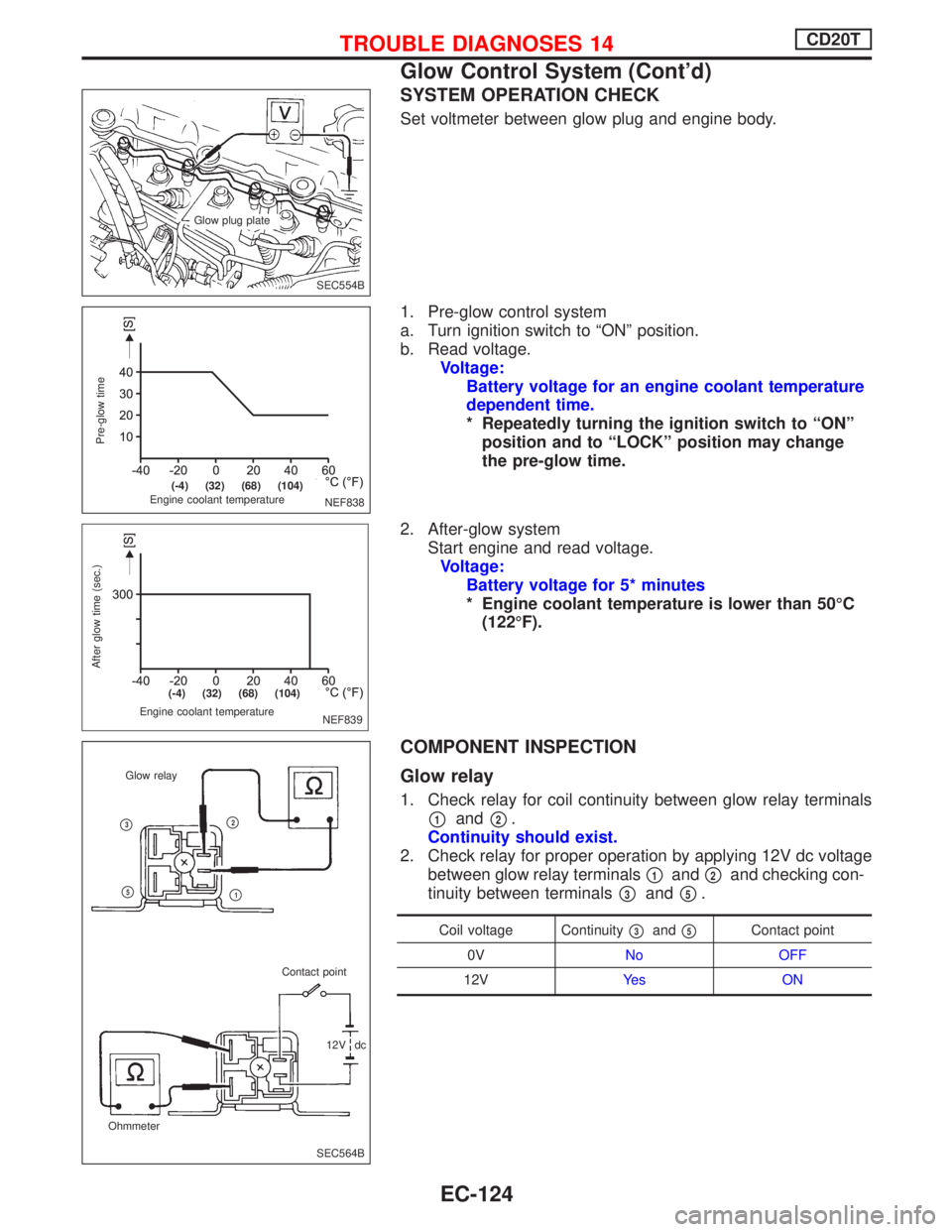
Set voltmeter between glow plug and engine body.
1. Pre-glow control system
a. Turn ignition switch to ªONº position.
b. Read voltage.
Voltage:
Battery voltage for an engine coolant temperature
dependent time.
* Repeatedly turning the ignition switch to ªONº
position and to ªLOCKº position may change
the pre-glow time.
2. After-glow system
Start engine and read voltage.
Voltage:
Battery voltage for 5* minutes
* Engine coolant temperature is lower than 50ÉC
(122ÉF).
COMPONENT INSPECTION
Glow relay
1. Check relay for coil continuity between glow relay terminals
p1andp2.
Continuity should exist.
2. Check relay for proper operation by applying 12V dc voltage
between glow relay terminals
p1andp2and checking con-
tinuity between terminals
p3andp5.
Coil voltage Continuityp3andp5Contact point
0VNo OFF
12VYe s O N
SEC554B Glow plug plate
NEF838
Pre-glow time
Engine coolant temperature
.(-4) (32) (68) (104)
NEF839 Engine coolant temperature
After glow time (sec.)
.(-4) (32) (68) (104)
SEC564B OhmmeterGlow relay
Contact point
12V dc
p2
p1
p3
p5
TROUBLE DIAGNOSES 14CD20T
Glow Control System (Cont'd)
EC-124
Page 834 of 2267
Idle Speed/Ignition Timing/Idle Mixture Ratio
Adjustment
NCEC0028PREPARATIONNCEC0028S01IMake sure that the following parts are in good order.
a)Battery
b)Ignition system
c)Engine oil and coolant levels
d)Fuses
e)ECM harness connector
f)Vacuum hoses
g)Air intake system
(Oil filler cap, oil level gauge, etc.)
h)Fuel pressure
i)Engine compression
j)Throttle valve
k)EVAP system
IOn models equipped with air conditioner, checks should
be carried out while the air conditioner is ªOFFº.
IWhen checking idle speed on models equipped with CVT,
ignition timing and mixture ratio, checks should be carried
out while shift lever is in ªPº or ªNº position.
IWhen measuring ªCOº percentage, insert probe more
than 40 cm (15.7 in) into tail pipe.
ITurn off headlamps, heater blower, rear window defogger.
IOn vehicles equipped with daytime running light systems,
set lighting switch to the 1st position to light only small
lamps.
IKeep front wheels pointed straight ahead.
IIf engine stops immediately after starting or idle condition
is unstable, perform the following to initialize IACV-AAC
valve:
a)Stop engine and wait 9 seconds.
b)Turn ignition ªONº and wait 1 second.
c)Turn ignition ªOFFº and wait 9 seconds.
IMake the check after the cooling fan has stopped.
BASIC SERVICE PROCEDURESR20DE
Idle Speed/Ignition Timing/Idle Mixture Ratio Adjustment
EC-34
Page 1110 of 2267
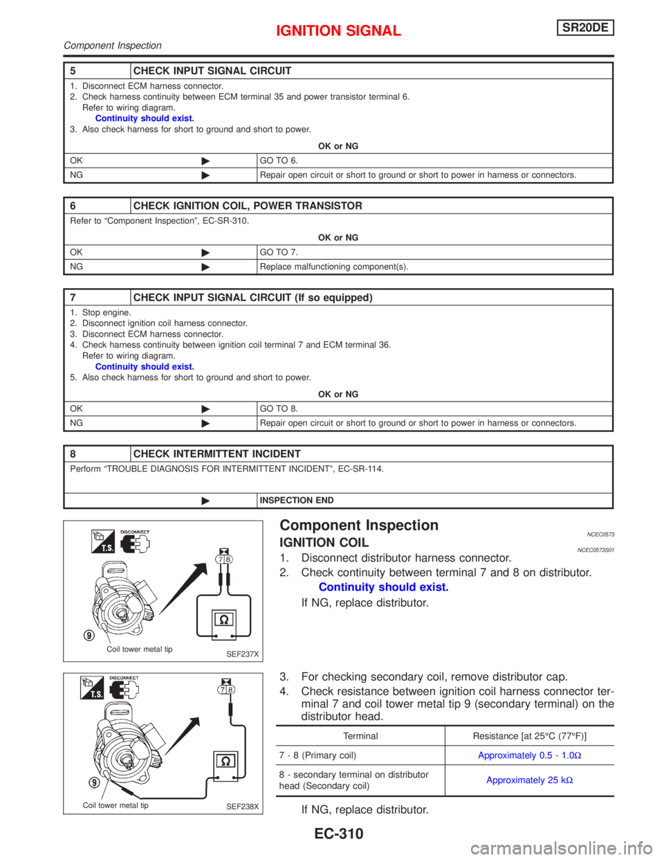
Component InspectionNCEC0573IGNITION COILNCEC0573S011. Disconnect distributor harness connector.
2. Check continuity between terminal 7 and 8 on distributor.
Continuity should exist.
If NG, replace distributor.
3. For checking secondary coil, remove distributor cap.
4. Check resistance between ignition coil harness connector ter-
minal 7 and coil tower metal tip 9 (secondary terminal) on the
distributor head.
Terminal Resistance [at 25ÉC (77ÉF)]
7 - 8 (Primary coil)Approximately 0.5 - 1.0W
8 - secondary terminal on distributor
head (Secondary coil)Approximately 25 kW
If NG, replace distributor.
5 CHECK INPUT SIGNAL CIRCUIT
1. Disconnect ECM harness connector.
2. Check harness continuity between ECM terminal 35 and power transistor terminal 6.
Refer to wiring diagram.
Continuity should exist.
3. Also check harness for short to ground and short to power.
OK or NG
OK©GO TO 6.
NG©Repair open circuit or short to ground or short to power in harness or connectors.
6 CHECK IGNITION COIL, POWER TRANSISTOR
Refer to ªComponent Inspectionº, EC-SR-310.
OK or NG
OK©GO TO 7.
NG©Replace malfunctioning component(s).
7 CHECK INPUT SIGNAL CIRCUIT (If so equipped)
1. Stop engine.
2. Disconnect ignition coil harness connector.
3. Disconnect ECM harness connector.
4. Check harness continuity between ignition coil terminal 7 and ECM terminal 36.
Refer to wiring diagram.
Continuity should exist.
5. Also check harness for short to ground and short to power.
OK or NG
OK©GO TO 8.
NG©Repair open circuit or short to ground or short to power in harness or connectors.
8 CHECK INTERMITTENT INCIDENT
Perform ªTROUBLE DIAGNOSIS FOR INTERMITTENT INCIDENTº, EC-SR-114.
©INSPECTION END
SEF237X Coil tower metal tip
SEF238X Coil tower metal tip
IGNITION SIGNALSR20DE
Component Inspection
EC-310
Page 1541 of 2267
ENGINE MECHANICAL
SECTION
EM
CONTENTS
PRECAUTIONS...............................................................5
Parts Requiring Angular Tightening .............................5
Liquid Gasket Application Procedure ..........................5
PREPARATION................................................................6
Special Service Tools ..................................................6
Commercial Service Tools .........................................10
QG
NOISE, VIBRATION AND HARSHNESS (NVH)
TROUBLESHOOTING................................................... 11
NVH Troubleshooting - Engine Noise ....................... 11
OUTER COMPONENT PARTS.....................................13
Removal and Installation ...........................................13
MEASUREMENT OF COMPRESSION PRESSURE....16
OIL PAN.........................................................................17
Components...............................................................17
Removal .....................................................................17
Installation ..................................................................18
TIMING CHAIN..............................................................19
Components...............................................................19
Removal .....................................................................20
Inspection...................................................................24
Installation ..................................................................24
OIL SEAL.......................................................................29
Replacement ..............................................................29
VALVE OIL SEAL.....................................................29
FRONT OIL SEAL....................................................29
REAR OIL SEAL......................................................30
CYLINDER HEAD..........................................................31
Components...............................................................31
Removal .....................................................................32
Disassembly...............................................................34
Inspection...................................................................34
CYLINDER HEAD DISTORTION...............................34
CAMSHAFT VISUAL CHECK....................................34
CAMSHAFT RUNOUT..............................................35
CAMSHAFT CAM HEIGHT.......................................35
CAMSHAFT JOURNAL CLEARANCE........................35
CAMSHAFT END PLAY............................................36
CAMSHAFT SPROCKET RUNOUT...........................36
VALVE GUIDE CLEARANCE....................................36
VALVE GUIDE REPLACEMENT................................37
VALVE SEATS.........................................................38
REPLACING VALVE SEAT FOR SERVICE PARTS.....38
VALVE DIMENSIONS...............................................39
VALVE SPRING.......................................................39
VALVE LIFTER AND VALVE SHIM.............................40
Valve Clearance.........................................................40
CHECKING.............................................................40
ADJUSTING............................................................41
Assembly ...................................................................43
Installation ..................................................................43
ENGINE REMOVAL.......................................................48
Removal and Installation ...........................................48
REMOVAL...............................................................49
INSTALLATION........................................................51
CYLINDER BLOCK.......................................................52
Components...............................................................52
Removal and Installation ...........................................53
Disassembly...............................................................53
PISTON AND CRANKSHAFT....................................53
Inspection...................................................................54
PISTON AND PISTON PIN CLEARANCE...................54
PISTON RING SIDE CLEARANCE............................54
PISTON RING END GAP..........................................54
CONNECTING ROD BEND AND TORSION...............55
CYLINDER BLOCK DISTORTION AND WEAR...........55
PISTON-TO-BORE CLEARANCE..............................56
CRANKSHAFT.........................................................57
BEARING CLEARANCE...........................................57
CONNECTING ROD BUSHING CLEARANCE
(Small end)
..............................................................59
REPLACEMENT OF CONNECTING ROD
BUSHING (Small end)
..............................................60
FLYWHEEL/DRIVE PLATE RUNOUT.........................60
EM
Page 1543 of 2267
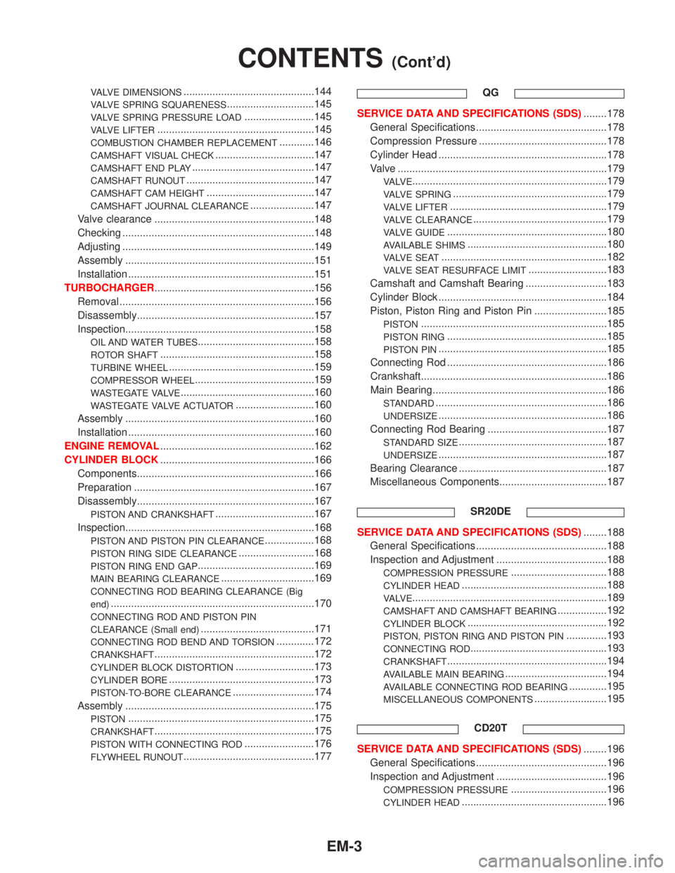
VALVE DIMENSIONS.............................................144
VALVE SPRING SQUARENESS..............................145
VALVE SPRING PRESSURE LOAD........................145
VALVE LIFTER......................................................145
COMBUSTION CHAMBER REPLACEMENT............146
CAMSHAFT VISUAL CHECK..................................147
CAMSHAFT END PLAY..........................................147
CAMSHAFT RUNOUT............................................147
CAMSHAFT CAM HEIGHT.....................................147
CAMSHAFT JOURNAL CLEARANCE......................147
Valve clearance .......................................................148
Checking ..................................................................148
Adjusting ..................................................................149
Assembly .................................................................151
Installation ................................................................151
TURBOCHARGER.......................................................156
Removal ...................................................................156
Disassembly.............................................................157
Inspection.................................................................158
OIL AND WATER TUBES........................................158
ROTOR SHAFT.....................................................158
TURBINE WHEEL..................................................159
COMPRESSOR WHEEL.........................................159
WASTEGATE VALVE..............................................160
WASTEGATE VALVE ACTUATOR...........................160
Assembly .................................................................160
Installation ................................................................160
ENGINE REMOVAL.....................................................162
CYLINDER BLOCK.....................................................166
Components.............................................................166
Preparation ..............................................................167
Disassembly.............................................................167
PISTON AND CRANKSHAFT..................................167
Inspection.................................................................168
PISTON AND PISTON PIN CLEARANCE.................168
PISTON RING SIDE CLEARANCE..........................168
PISTON RING END GAP........................................169
MAIN BEARING CLEARANCE................................169
CONNECTING ROD BEARING CLEARANCE (Big
end)
......................................................................170
CONNECTING ROD AND PISTON PIN
CLEARANCE (Small end)
.......................................171
CONNECTING ROD BEND AND TORSION.............172
CRANKSHAFT.......................................................172
CYLINDER BLOCK DISTORTION...........................173
CYLINDER BORE..................................................173
PISTON-TO-BORE CLEARANCE............................174
Assembly .................................................................175
PISTON................................................................175
CRANKSHAFT.......................................................175
PISTON WITH CONNECTING ROD........................176
FLYWHEEL RUNOUT.............................................177QG
SERVICE DATA AND SPECIFICATIONS (SDS)........178
General Specifications .............................................178
Compression Pressure ............................................178
Cylinder Head ..........................................................178
Valve ........................................................................179
VA LV E...................................................................179
VALVE SPRING.....................................................179
VALVE LIFTER......................................................179
VALVE CLEARANCE..............................................179
VALVE GUIDE.......................................................180
AVAILABLE SHIMS................................................180
VA LV E S E AT.........................................................182
VALVE SEAT RESURFACE LIMIT...........................183
Camshaft and Camshaft Bearing ............................183
Cylinder Block ..........................................................184
Piston, Piston Ring and Piston Pin .........................185
PISTON................................................................185
PISTON RING.......................................................185
PISTON PIN..........................................................185
Connecting Rod .......................................................186
Crankshaft................................................................186
Main Bearing............................................................186
STANDARD...........................................................186
UNDERSIZE..........................................................186
Connecting Rod Bearing .........................................187
STANDARD SIZE...................................................187
UNDERSIZE..........................................................187
Bearing Clearance ...................................................187
Miscellaneous Components.....................................187
SR20DE
SERVICE DATA AND SPECIFICATIONS (SDS)........188
General Specifications .............................................188
Inspection and Adjustment ......................................188
COMPRESSION PRESSURE.................................188
CYLINDER HEAD..................................................188
VA LV E...................................................................189
CAMSHAFT AND CAMSHAFT BEARING.................192
CYLINDER BLOCK................................................192
PISTON, PISTON RING AND PISTON PIN..............193
CONNECTING ROD...............................................193
CRANKSHAFT.......................................................194
AVAILABLE MAIN BEARING...................................194
AVAILABLE CONNECTING ROD BEARING.............195
MISCELLANEOUS COMPONENTS.........................195
CD20T
SERVICE DATA AND SPECIFICATIONS (SDS)........196
General Specifications .............................................196
Inspection and Adjustment ......................................196
COMPRESSION PRESSURE.................................196
CYLINDER HEAD..................................................196
CONTENTS(Cont'd)
EM-3
Page 1551 of 2267
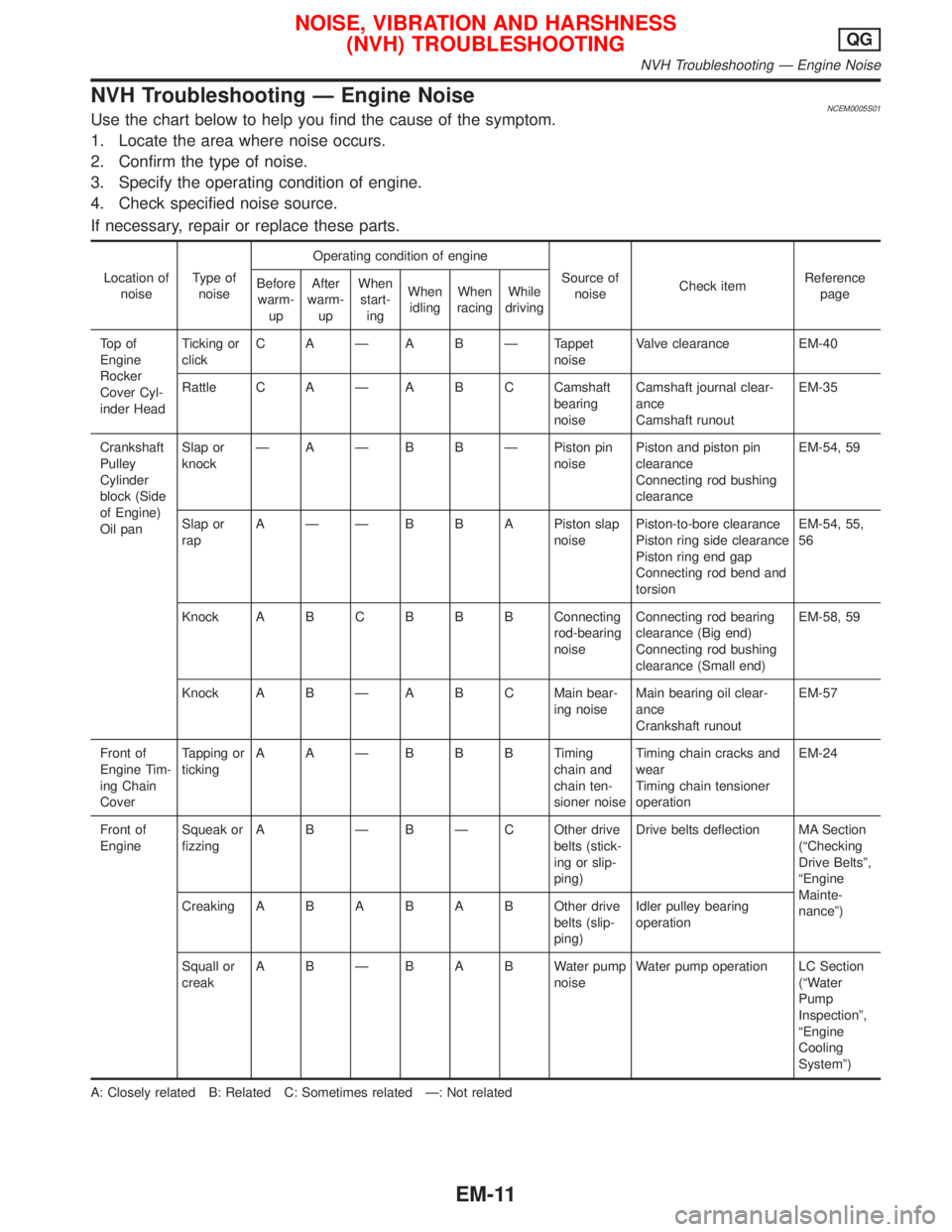
NVH Troubleshooting Ð Engine NoiseNCEM0005S01Use the chart below to help you find the cause of the symptom.
1. Locate the area where noise occurs.
2. Confirm the type of noise.
3. Specify the operating condition of engine.
4. Check specified noise source.
If necessary, repair or replace these parts.
Location of
noiseType of
noiseOperating condition of engine
Source of
noiseCheck itemReference
page Before
warm-
upAfter
warm-
upWhen
start-
ingWhen
idlingWhen
racingWhile
driving
To p o f
Engine
Rocker
Cover Cyl-
inder HeadTicking or
clickC A Ð A B Ð Tappet
noiseValve clearance EM-40
Rattle C A Ð A B C Camshaft
bearing
noiseCamshaft journal clear-
ance
Camshaft runoutEM-35
Crankshaft
Pulley
Cylinder
block (Side
of Engine)
Oil panSlap or
knockÐ A Ð B B Ð Piston pin
noisePiston and piston pin
clearance
Connecting rod bushing
clearanceEM-54, 59
Slap or
rapA Ð Ð B B A Piston slap
noisePiston-to-bore clearance
Piston ring side clearance
Piston ring end gap
Connecting rod bend and
torsionEM-54, 55,
56
Knock A B CB B B Connecting
rod-bearing
noiseConnecting rod bearing
clearance (Big end)
Connecting rod bushing
clearance (Small end)EM-58, 59
Knock A B Ð A B C Main bear-
ing noiseMain bearing oil clear-
ance
Crankshaft runoutEM-57
Front of
Engine Tim-
ing Chain
CoverTapping or
tickingAAÐBBBTiming
chain and
chain ten-
sioner noiseTiming chain cracks and
wear
Timing chain tensioner
operationEM-24
Front of
EngineSqueak or
fizzingA B Ð B Ð C Other drive
belts (stick-
ing or slip-
ping)Drive belts deflection MA Section
(ªChecking
Drive Beltsº,
ªEngine
Mainte-
nanceº) CreakingABABABOther drive
belts (slip-
ping)Idler pulley bearing
operation
Squall or
creakABÐBABWater pump
noiseWater pump operation LC Section
(ªWater
Pump
Inspectionº,
ªEngine
Cooling
Systemº)
A: Closely related B: Related C: Sometimes related Ð: Not related
NOISE, VIBRATION AND HARSHNESS
(NVH) TROUBLESHOOTINGQG
NVH Troubleshooting Ð Engine Noise
EM-11