1999 NISSAN PRIMERA service reset
[x] Cancel search: service resetPage 476 of 2267
5. Turn ignition switch ªOFFº and wait at least 9 seconds.
6. Start the engine and let it to idle for at least 28 seconds.
7. Select ªIDLE AIR VOL LEARNº in ªWORK SUPPORTº mode.
8. Touch ªSTARTº and wait 20 seconds.
9. Make sure that ªCMPLTº is displayed on CONSULT-II screen.
If ªINCMPº is displayed, ªIdle Air Volume Learningº will not be
carried out successfully. In this case, find the cause of the
problem by referring to the NOTE below.
10. Rev up the engine two or three times. Make sure that idle
speed and ignition timing are close to or within specifications.
ITEM SPECIFICATION
Idle speed 700 50 rpm
Ignition timing 8É 5É BTDC
Without CONSULT-IINCEC0541S02021. Turn ignition switch ªONº and wait at least 1 second.
2. Turn ignition switch ªOFFº and wait at least 9 seconds.
3. Start the engine and warm it up to normal operating tempera-
ture.
4. Check that all items listed under the topic ªPRE-CONDITION-
INGº (previously mentioned) are in good order.
5. Turn ignition switch ªOFFº and wait at least 9 seconds.
6. Start the engine and let it to idle for at least 28 seconds.
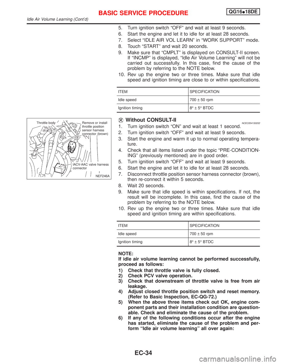
7. Disconnect throttle position sensor harness connector (brown),
then re-connect it within 5 seconds.
8. Wait 20 seconds.
9. Make sure that idle speed is within specifications. If not, the
result will be incomplete. In this case, find the cause of the
problem by referring to the NOTE below.
10. Rev up the engine two or three times. Make sure that idle
speed and ignition timing are within specifications.
ITEM SPECIFICATION
Idle speed 700 50 rpm
Ignition timing 8É 5É BTDC
NOTE:
If idle air volume learning cannot be performed successfully,
proceed as follows:
1) Check that throttle valve is fully closed.
2) Check PCV valve operation.
3) Check that downstream of throttle valve is free from air
leakage.
4) Adjust closed throttle position switch and reset memory.
(Refer to Basic Inspection, EC-QG-72.)
5) When the above three items check out OK, engine com-
ponent parts and their installation condition are question-
able. Check and eliminate the cause of the problem.
6) If any of the following conditions occur after the engine
has started, eliminate the cause of the problem and per-
form ªIdle air volume learningº all over again:
NEF246A Throttle body
.Remove or install
throttle position
sensor harness
connector (brown)
IACV-AAC valve harness
connector
BASIC SERVICE PROCEDUREQG16I18DE
Idle Air Volume Learning (Cont'd)
EC-34
Page 847 of 2267
Without CONSULT-IINCEC0541S02021. Start engine and warm it up to normal operating temperature.
2. Check that all items listed under the topic ªPre-Conditioningº
(previously mentioned) are in good order.
3. Turn ignition switch ªOFFº and wait at least 9 seconds.
4. Start the engine and allow it to idle for at least 28 seconds.
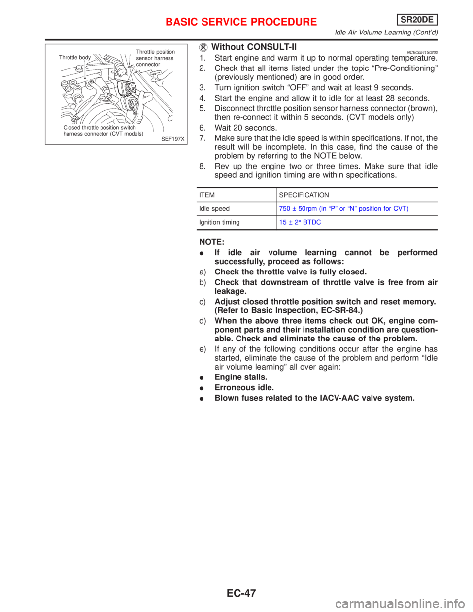
5. Disconnect throttle position sensor harness connector (brown),
then re-connect it within 5 seconds. (CVT models only)
6. Wait 20 seconds.
7. Make sure that the idle speed is within specifications. If not, the
result will be incomplete. In this case, find the cause of the
problem by referring to the NOTE below.
8. Rev up the engine two or three times. Make sure that idle
speed and ignition timing are within specifications.
ITEM SPECIFICATION
Idle speed750 50rpm (in ªPº or ªNº position for CVT)
Ignition timing15 2É BTDC
NOTE:
IIf idle air volume learning cannot be performed
successfully, proceed as follows:
a)Check the throttle valve is fully closed.
b)Check that downstream of throttle valve is free from air
leakage.
c)Adjust closed throttle position switch and reset memory.
(Refer to Basic Inspection, EC-SR-84.)
d)When the above three items check out OK, engine com-
ponent parts and their installation condition are question-
able. Check and eliminate the cause of the problem.
e) If any of the following conditions occur after the engine has
started, eliminate the cause of the problem and perform ªIdle
air volume learningº all over again:
IEngine stalls.
IErroneous idle.
IBlown fuses related to the IACV-AAC valve system.
SEF197X
Throttle bodyThrottle position
sensor harness
connector
Closed throttle position switch
harness connector (CVT models)
BASIC SERVICE PROCEDURESR20DE
Idle Air Volume Learning (Cont'd)
EC-47
Page 1284 of 2267
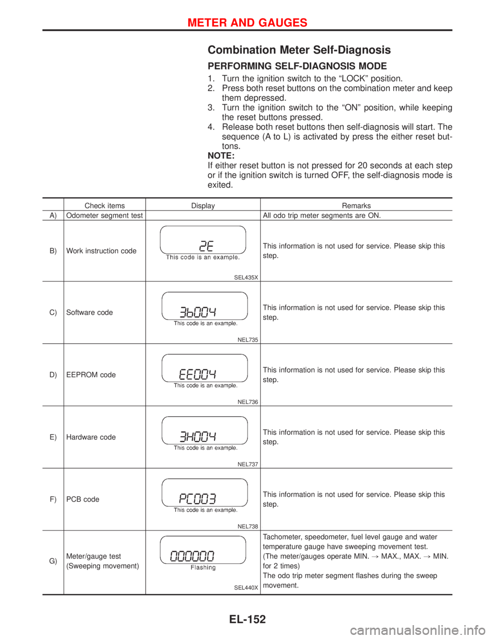
Combination Meter Self-Diagnosis
PERFORMING SELF-DIAGNOSIS MODE
1. Turn the ignition switch to the“LOCK”position.
2. Press both reset buttons on the combination meter and keep
them depressed.
3. Turn the ignition switch to the“ON”position, while keeping
the reset buttons pressed.
4. Release both reset buttons then self-diagnosis will start. The
sequence (A to L) is activated by press the either reset but-
tons.
NOTE:
If either reset button is not pressed for 20 seconds at each step
or if the ignition switch is turned OFF, the self-diagnosis mode is
exited.
Check items Display Remarks
A) Odometer segment test All odo trip meter segments are ON.
B) Work instruction code
SEL435X
This information is not used for service. Please skip this
step.
C) Software code
NEL735
This information is not used for service. Please skip this
step.
D) EEPROM code
NEL736
This information is not used for service. Please skip this
step.
E) Hardware code
NEL737
This information is not used for service. Please skip this
step.
F) PCB code
NEL738
This information is not used for service. Please skip this
step.
G)Meter/gauge test
(Sweeping movement)
SEL440X
Tachometer, speedometer, fuel level gauge and water
temperature gauge have sweeping movement test.
(The meter/gauges operate MIN.,MAX., MAX.,MIN.
for 2 times)
The odo trip meter segment flashes during the sweep
movement.
METER AND GAUGES
EL-152
Page 1348 of 2267
Anti-theft System
NATS Audio Link
Description
The link with the NATS IMMU implies that the audio unit can basically only be operated if connected to the
matching NATS IMMU to which the audio unit was initially fitted on the production line.
Since radio operation is impossible after the link with the NATS is disrupted theft of the audio unit is basi-
cally useless since special equipment is required to reset the audio unit.
Initialization process for audio units that are linked to the NATS IMMU
New audio units will be delivered to the factories in the“NEW”state, i.e. ready to be linked with the vehi-
cle’s NATS. When the audio unit in“NEW”state is first switched on at the factory, it will start up communi-
cation with the vehicle’s immobiliser control unit (IMMU) and send a code (the“audio unit Code”)tothe
IMMU. The IMMU will then store this code, which is unique to each audio unit, in its (permanent) memory.
Upon receipt of the code by the IMMU, the NATS will confirm correct receipt of the audio unit code to the
audio unit. Hereafter, the audio unit will operate as normal.
During the initialisation process,“NEW”is displayed on the audio unit display. Normally though, communi-
cation between audio unit and IMMU takes such a short time (300 ms) that the audio unit seems to switch
on directly without showing“NEW”on its display.
Normal operation
Each time the audio unit is switched on afterwards, the audio unit code will be verified between the audio
unit and the NATS before the audio unit becomes operational. During the code verification process,“WAIT”
is shown on the audio unit display. Again, the communication takes such a short time (300 ms) that the audio
unit seems to switch on directly without showing“WAIT”on its display.
When the radio is locked
In case of a audio unit being linked with the vehicle’s NATS (immobilizer system), disconnection of the link
between the audio unit and the IMMU will cause the audio unit to switch into the lock (“SECURE”) mode in
which the audio unit is fully inoperative. Hence, repair of the audio unit is basically impossible, unless the
audio unit is reset to the“NEW”state for which special decoding equipment is required.
The radio manufacturer has provided their authorized service representatives with so called“decoder boxes”
which can bring the audio unit back to the“NEW”state, enabling the audio unit to be switched on after which
repair can be carried out. Subsequently, when the repaired audio unit is delivered to the final user again, it
will be in the“NEW”state as to enable re-linking the audio unit to the vehicle’s immobiliser system. As a
result of the above, repair of the audio unit can only be done by an authorized representative of the radio
manufacturer.
Service instruction
Item Radio linked with IMMU and/or SECU
Battery disconnection No additional action required
Radio needs repair Repair needs to be done by authorised representative of radio manufacturer since radio cannot
be operated unless it is reset to NEW state, using special decoding equipment
Replacement of radio by new part Radio is delivered in NEW state. If possible, the radio will automatically link up with the immobil-
iser system. If this appears not possible, the audio unit code needs to be manually input
Transferring radio to another
vehicle / replacement of radio by
an‘‘old’’partRadio needs to be reset to NEW state by authorised representative of radio manufacturer
Replacement of IMMU by new part Radio will request for the audio unit code input prior to establishing the link with the IMMU
Replacement of IMMU by old part If a radio code has already been stored in memory of the IMMU, the radio cannot be linked to it.
After switching on the radio, it will display‘‘SECURE’’after 1 minute. Operation can only be
established after resetting the ratio by an authorised representative of radio manufacturer
No communication from IMMU to radio Radio will display‘‘SECURE’’after 180 attempts to communicate with IMMU. Further use of radio
impossible until communication is established again, or after radio is reset by authorised repre-
sentative of (radio) manufacturer
AUDIO
EL-216
Page 1635 of 2267
VALVE SEATS
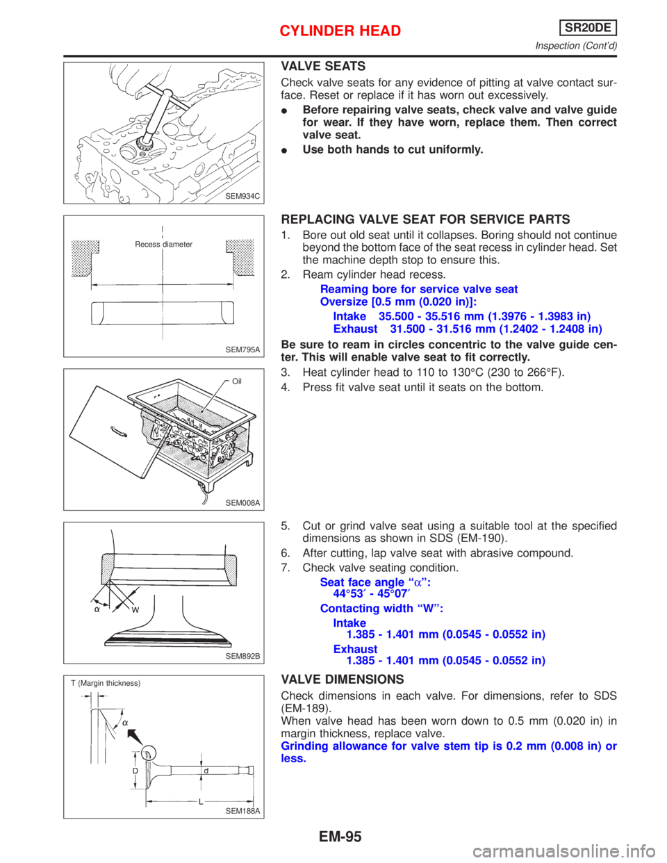
Check valve seats for any evidence of pitting at valve contact sur-
face. Reset or replace if it has worn out excessively.
IBefore repairing valve seats, check valve and valve guide
for wear. If they have worn, replace them. Then correct
valve seat.
IUse both hands to cut uniformly.
REPLACING VALVE SEAT FOR SERVICE PARTS
1. Bore out old seat until it collapses. Boring should not continue
beyond the bottom face of the seat recess in cylinder head. Set
the machine depth stop to ensure this.
2. Ream cylinder head recess.
Reaming bore for service valve seat
Oversize [0.5 mm (0.020 in)]:
Intake 35.500 - 35.516 mm (1.3976 - 1.3983 in)
Exhaust 31.500 - 31.516 mm (1.2402 - 1.2408 in)
Be sure to ream in circles concentric to the valve guide cen-
ter. This will enable valve seat to fit correctly.
3. Heat cylinder head to 110 to 130ÉC (230 to 266ÉF).
4. Press fit valve seat until it seats on the bottom.
5. Cut or grind valve seat using a suitable tool at the specified
dimensions as shown in SDS (EM-190).
6. After cutting, lap valve seat with abrasive compound.
7. Check valve seating condition.
Seat face angle ªaº:
44É53¢- 45É07¢
Contacting width ªWº:
Intake
1.385 - 1.401 mm (0.0545 - 0.0552 in)
Exhaust
1.385 - 1.401 mm (0.0545 - 0.0552 in)
VALVE DIMENSIONS
Check dimensions in each valve. For dimensions, refer to SDS
(EM-189).
When valve head has been worn down to 0.5 mm (0.020 in) in
margin thickness, replace valve.
Grinding allowance for valve stem tip is 0.2 mm (0.008 in) or
less.
SEM934C
SEM795A
.Recess diameter
SEM008AOil
SEM892B
.SEM188A T (Margin thickness)
CYLINDER HEADSR20DE
Inspection (Cont'd)
EM-95
Page 1749 of 2267
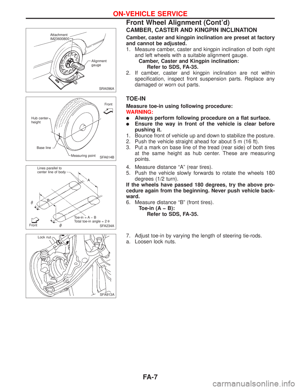
CAMBER, CASTER AND KINGPIN INCLINATION
Camber, caster and kingpin inclination are preset at factory
and cannot be adjusted.
1. Measure camber, caster and kingpin inclination of both right
and left wheels with a suitable alignment gauge.
Camber, Caster and Kingpin inclination:
Refer to SDS, FA-35.
2. If camber, caster and kingpin inclination are not within
specification, inspect front suspension parts. Replace any
damaged or worn out parts.
TOE-IN
Measure toe-in using following procedure:
WARNING:
lAlways perform following procedure on a flat surface.
lEnsure the way in front of the vehicle is clear before
pushing it.
1. Bounce front of vehicle up and down to stabilize the posture.
2. Push the vehicle straight ahead for about 5 m (16 ft).
3. Put a mark on base line of the tread (rear side) of both tires
at the same height as hub center. These are measuring
points.
4. Measure distance ªAº (rear tires).
5. Push the vehicle slowly forwards to rotate the wheels 180
degrees (1/2 turn).
If the wheels have passed 180 degrees, try the above pro-
cedure again from the beginning. Never push vehicle back-
ward.
6. Measure distance ªBº (front tires).
Toe-in (A þ B):
Refer to SDS, FA-35.
7. Adjust toe-in by varying the length of steering tie-rods.
a. Loosen lock nuts.
SRA096A Attachment
IM23600800
Alignment
gauge
SFA614B Hub center
height
Base line
Measuring pointFront
SFA234A FrontLines parallel to
center line of body
Toe-in = A þ B
Total toe-in angle = 2q
.SFA913A Lock nut
ON-VEHICLE SERVICE
Front Wheel Alignment (Cont'd)
FA-7
Page 2175 of 2267
Rear Wheel Alignment
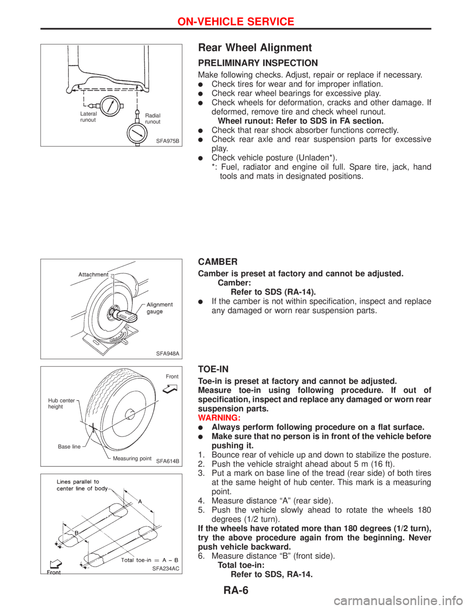
PRELIMINARY INSPECTION
Make following checks. Adjust, repair or replace if necessary.
lCheck tires for wear and for improper inflation.
lCheck rear wheel bearings for excessive play.
lCheck wheels for deformation, cracks and other damage. If
deformed, remove tire and check wheel runout.
Wheel runout: Refer to SDS in FA section.
lCheck that rear shock absorber functions correctly.
lCheck rear axle and rear suspension parts for excessive
play.
lCheck vehicle posture (Unladen*).
*: Fuel, radiator and engine oil full. Spare tire, jack, hand
tools and mats in designated positions.
CAMBER
Camber is preset at factory and cannot be adjusted.
Camber:
Refer to SDS (RA-14).
lIf the camber is not within specification, inspect and replace
any damaged or worn rear suspension parts.
TOE-IN
Toe-in is preset at factory and cannot be adjusted.
Measure toe-in using following procedure. If out of
specification, inspect and replace any damaged or worn rear
suspension parts.
WARNING:
lAlways perform following procedure on a flat surface.
lMake sure that no person is in front of the vehicle before
pushing it.
1. Bounce rear of vehicle up and down to stabilize the posture.
2. Push the vehicle straight ahead about 5 m (16 ft).
3. Put a mark on base line of the tread (rear side) of both tires
at the same height of hub center. This mark is a measuring
point.
4. Measure distance ªAº (rear side).
5. Push the vehicle slowly ahead to rotate the wheels 180
degrees (1/2 turn).
If the wheels have rotated more than 180 degrees (1/2 turn),
try the above procedure again from the beginning. Never
push vehicle backward.
6. Measure distance ªBº (front side).
Total toe-in:
Refer to SDS, RA-14.
SFA975B Radial
runout Lateral
runout
SFA948A
SFA614BFront
Hub center
height
Base line
Measuring point
SFA234AC
ON-VEHICLE SERVICE
RA-6
Page 2211 of 2267
Trouble Diagnoses Introduction
CAUTION:
lDo not use electrical test equipment on any circuit related to the SRS unless instructed to in this
Service Manual. Spiral cable and SRS wiring harnesses (except ªSEAT BELT PRE-TENSIONER
CONNECTORº) can be identified by yellow harness connector (and with yellow harness protec-
tor or yellow insulation tape before the harness connectors.
lDo not attempt to repair, splice or modify the SRS wiring harness. If the harness is damaged,
replace it with a new one.
lKeep ground portion clean.
DIAGNOSIS FUNCTION
The SRS self-diagnosis results can be read by using ªAIR BAGº warning lamp and/or CONSULT-II. The
reading of these results is accomplished using one of two modes Ð ªUser modeº and ªDiagnosis modeº.
The User mode is exclusively prepared for the customer (driver). This mode warns the driver of a system
malfunction through the operation of the ªAIR BAGº warning lamp.
The Diagnosis mode allows the technician to locate and inspect the malfunctioning part.
The mode applications for the ªAIR BAGº warning lamp and CONSULT-II are as follows:
User mode Diagnosis mode Display type
ªAIR BAGº warning lamp X XON-OFF operation
CONSULT-II Ð XMonitoring
lSeat belt pre-tensioner system can only be diagnosed by CONSULT-II.
DIAGNOSIS MODE FOR CONSULT-II
lSELF-DIAG [CURRENT]
A current Self-diagnosis result (also indicated by the number of warning lamp flashes in the Diagnosis
mode) is displayed on the CONSULT-II screen in real time. This refers to a malfunctioning part requir-
ing repairs.
lSELF-DIAG [PAST]
Diagnosis results previously stored in the memory (also indicated by the warning lamp flashes in the
Diagnosis mode) are displayed on the CONSULT-II screen. The stored results are not erased until
memory erasing is executed.
lTROUBLE DIAG RECORD
With TROUBLE DIAG RECORD, diagnosis results previously erased by a reset operation can be dis-
played on the CONSULT-II screen.
lªECU DISCRIMINATED NO.º
The diagnosis sensor unit for each vehicle model is assigned with its own, individual classification num-
ber (refer to the table below). This number will be displayed on the CONSULT-II screen. When replac-
ing the diagnosis sensor unit, refer to the part number for the compatibility. After installation, replace-
ment with a correct unit can be checked by confirming this classification number on the CONSULT-II
screen.
For NISSAN MODEL P11, the diagnosis sensor unit classification numbers are as follows:
MODEL ECU DISCRIMINATED NO.
Models with single air bag and seat belt pre-tensioner A914
Models with dual air bags and seat belt pre-tensioner A915
Models with dual air bags, side air bag and seat belt pre-tensioner A916
TROUBLE DIAGNOSES Ð Supplemental Restraint System (SRS)
RS-28