1999 NISSAN PRIMERA fuel pump
[x] Cancel search: fuel pumpPage 295 of 2267
ENGINE CONTROL SYSTEM
SECTION
EC
CONTENTS
CD20T
PRECAUTIONS AND PREPARATION.......................... 3
Special Service Tools ................................................ 3
Engine Fuel & Emission Control System .................. 5
Supplemental Restraint System (SRS)²AIR
BAG²and²SEAT BELT PRE-TENSIONER²............. 6
Precautions for On Board Diagnostic (OBD)
System of Engine ...................................................... 6
Precautions ................................................................ 7
ENGINE AND EMISSION CONTROL OVERALL
SYSTEM......................................................................... 9
Engine Control Module Component Parts
Location ..................................................................... 9
Circuit Diagram ......................................................... 11
System Diagram ...................................................... 12
Vacuum Hose Drawing ............................................ 13
System Chart ........................................................... 14
ENGINE AND EMISSION BASIC CONTROL
SYSTEM DESCRIPTION............................................. 15
Glow Control System ............................................... 15
Fuel Injection System .............................................. 15
Fuel Injection Timing System .................................. 18
Air Conditioning Cut Control .................................... 20
Cooling Fan Control................................................. 20
CRANKCASE VENTILATION SYSTEM...................... 21
Description ............................................................... 21
Blow-by Control Valve ............................................. 21
Ventilation Hose ....................................................... 21
INJECTION NOZZLE................................................... 22
Removal and Installation ......................................... 22
Test and Adjustment ................................................ 22
ELECTRONIC FUEL INJECTION PUMP.................... 24
Removal ................................................................... 24
Installation ................................................................ 25Disassembly and Assembly ..................................... 26
ON BOARD DIAGNOSTIC SYSTEM
DESCRIPTION............................................................. 27
CONSULT-II ............................................................. 27
TROUBLE DIAGNOSIS - INTRODUCTION................ 33
Introduction .............................................................. 33
Diagnostic Worksheet .............................................. 34
TROUBLE DIAGNOSIS - WORK FLOW.................... 35
Work Flow ................................................................ 35
Description for Work Flow ....................................... 36
TROUBLE DIAGNOSIS - BASIC INSPECTION......... 37
Basic Inspection....................................................... 37
TROUBLE DIAGNOSIS - GENERAL
DESCRIPTION............................................................. 39
Diagnostic Trouble Chart ......................................... 39
Symptom Matrix Chart ............................................. 47
CONSULT-II Reference Value in Data Monitor
Mode ........................................................................ 50
Major Sensor Reference Graph in Data Monitor
Mode ........................................................................ 51
ECM Terminals and Reference Value ..................... 52
TROUBLE DIAGNOSIS FOR POWER SUPPLY........ 59
Main Power Supply and Ground Circuit .................. 59
TROUBLE DIAGNOSIS 1............................................ 62
Mass Air Flow Sensor (MAFS) ................................ 62
TROUBLE DIAGNOSIS 2............................................ 66
Engine Coolant Temperature (ECT) Sensor ........... 66
TROUBLE DIAGNOSIS 3............................................ 70
Vehicle Speed Sensor (VSS) .................................. 70
TROUBLE DIAGNOSIS 4............................................ 74
Control Sleeve Position Sensor (CSPS) ................. 74
TROUBLE DIAGNOSIS 5............................................ 78
Electric Governor ..................................................... 78
TROUBLE DIAGNOSIS 6............................................ 82
EC
Page 299 of 2267
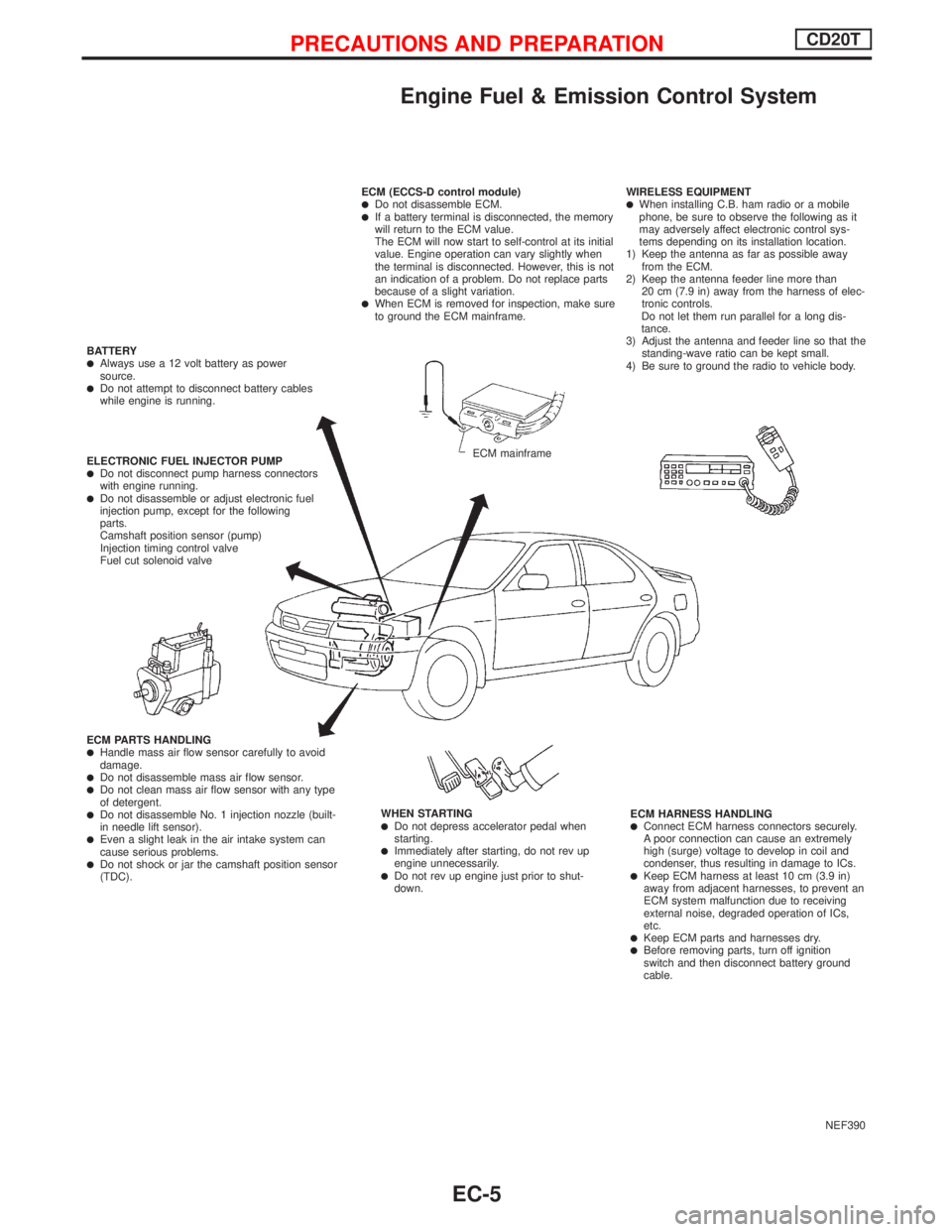
Engine Fuel & Emission Control System
NEF390 ECM (ECCS-D control module)
lDo not disassemble ECM.lIf a battery terminal is disconnected, the memory
will return to the ECM value.
The ECM will now start to self-control at its initial
value. Engine operation can vary slightly when
the terminal is disconnected. However, this is not
an indication of a problem. Do not replace parts
because of a slight variation.
lWhen ECM is removed for inspection, make sure
to ground the ECM mainframe.WIRELESS EQUIPMENT
lWhen installing C.B. ham radio or a mobile
phone, be sure to observe the following as it
may adversely affect electronic control sys-
tems depending on its installation location.
1) Keep the antenna as far as possible away
from the ECM.
2) Keep the antenna feeder line more than
20 cm (7.9 in) away from the harness of elec-
tronic controls.
Do not let them run parallel for a long dis-
tance.
3) Adjust the antenna and feeder line so that the
standing-wave ratio can be kept small.
4) Be sure to ground the radio to vehicle body.
ECM HARNESS HANDLING
lConnect ECM harness connectors securely.
A poor connection can cause an extremely
high (surge) voltage to develop in coil and
condenser, thus resulting in damage to ICs.
lKeep ECM harness at least 10 cm (3.9 in)
away from adjacent harnesses, to prevent an
ECM system malfunction due to receiving
external noise, degraded operation of ICs,
etc.
lKeep ECM parts and harnesses dry.lBefore removing parts, turn off ignition
switch and then disconnect battery ground
cable. WHEN STARTING
lDo not depress accelerator pedal when
starting.
lImmediately after starting, do not rev up
engine unnecessarily.
lDo not rev up engine just prior to shut-
down. ECM PARTS HANDLING
lHandle mass air flow sensor carefully to avoid
damage.
lDo not disassemble mass air flow sensor.lDo not clean mass air flow sensor with any type
of detergent.
lDo not disassemble No. 1 injection nozzle (built-
in needle lift sensor).
lEven a slight leak in the air intake system can
cause serious problems.
lDo not shock or jar the camshaft position sensor
(TDC). ELECTRONIC FUEL INJECTOR PUMP
lDo not disconnect pump harness connectors
with engine running.
lDo not disassemble or adjust electronic fuel
injection pump, except for the following
parts.
Camshaft position sensor (pump)
Injection timing control valve
Fuel cut solenoid valve BATTERY
lAlways use a 12 volt battery as power
source.
lDo not attempt to disconnect battery cables
while engine is running.
ECM mainframe
PRECAUTIONS AND PREPARATIONCD20T
EC-5
Page 309 of 2267
Glow Control System
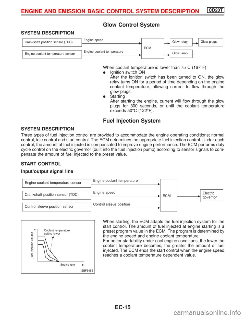
SYSTEM DESCRIPTION
Crankshaft position sensor (TDC)EEngine speed
ECMEGlow relayEGlow plugs
Engine coolant temperature sensorEEngine coolant temperatureEGlow lamp
When coolant temperature is lower than 75ÉC (167ÉF):
lIgnition switch ON
After the ignition switch has been turned to ON, the glow
relay turns ON for a period of time depending on the engine
coolant temperature, allowing current to flow through the
glow plugs.
lStarting
After starting the engine, current will flow through the glow
plugs for 300 seconds, or until the coolant temperature
exceeds 50ÉC (122ÉF).
Fuel Injection System
SYSTEM DESCRIPTION
Three types of fuel injection control are provided to accommodate the engine operating conditions; normal
control, idle control and start control. The ECM determines the appropriate fuel injection control. Under each
control, the amount of fuel injected is compensated to improve engine performance. The ECM performs duty
cycle control on the electric governor (built into the fuel injection pump) according to sensor signals to com-
pensate the amount of fuel injected to the preset value.
START CONTROL
Input/output signal line
Engine coolant temperature sensorEEngine coolant temperature
ECM
EElectric
governorCrankshaft position sensor (TDC)EEngine speed
Control sleeve position sensor
EControl sleeve position
When starting, the ECM adapts the fuel injection system for the
start control. The amount of fuel injected at engine starting is a
preset program value in the ECM. The program is determined by
the engine speed and engine coolant temperature.
For better startability under cool engine conditions, the lower the
coolant temperature becomes, the greater the amount of fuel
injected. The ECM ends the start control when the engine speed
reaches a coolant temperature dependent value.
SEF648S Coolant temperature
getting lower
Engine rpm
Fuel injection volume
ENGINE AND EMISSION BASIC CONTROL SYSTEM DESCRIPTIONCD20T
EC-15
Page 311 of 2267
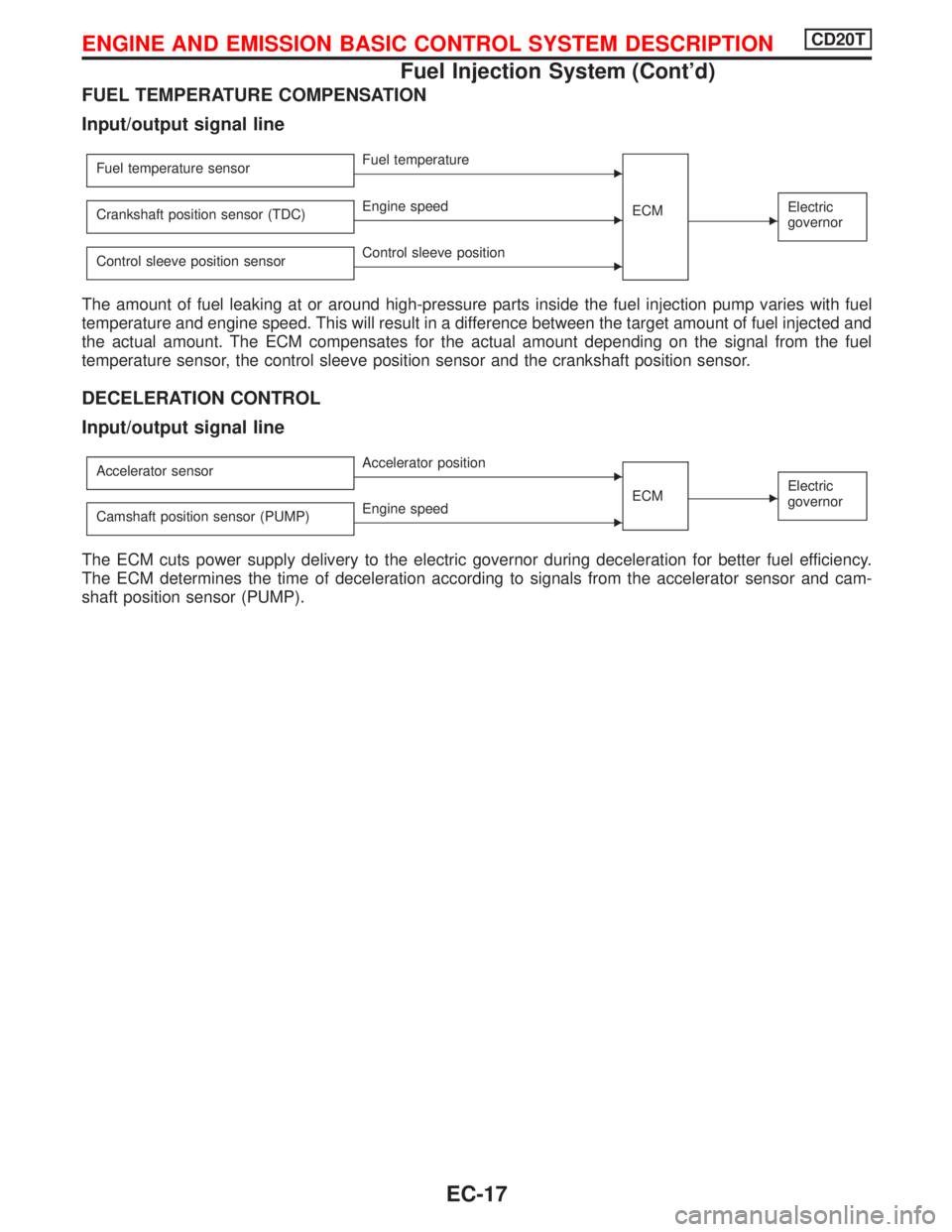
FUEL TEMPERATURE COMPENSATION
Input/output signal line
Fuel temperature sensorEFuel temperature
ECM
EElectric
governorCrankshaft position sensor (TDC)EEngine speed
Control sleeve position sensor
EControl sleeve position
The amount of fuel leaking at or around high-pressure parts inside the fuel injection pump varies with fuel
temperature and engine speed. This will result in a difference between the target amount of fuel injected and
the actual amount. The ECM compensates for the actual amount depending on the signal from the fuel
temperature sensor, the control sleeve position sensor and the crankshaft position sensor.
DECELERATION CONTROL
Input/output signal line
Accelerator sensorEAccelerator position
ECM
EElectric
governor
Camshaft position sensor (PUMP)EEngine speed
The ECM cuts power supply delivery to the electric governor during deceleration for better fuel efficiency.
The ECM determines the time of deceleration according to signals from the accelerator sensor and cam-
shaft position sensor (PUMP).
ENGINE AND EMISSION BASIC CONTROL SYSTEM DESCRIPTIONCD20T
Fuel Injection System (Cont'd)
EC-17
Page 318 of 2267
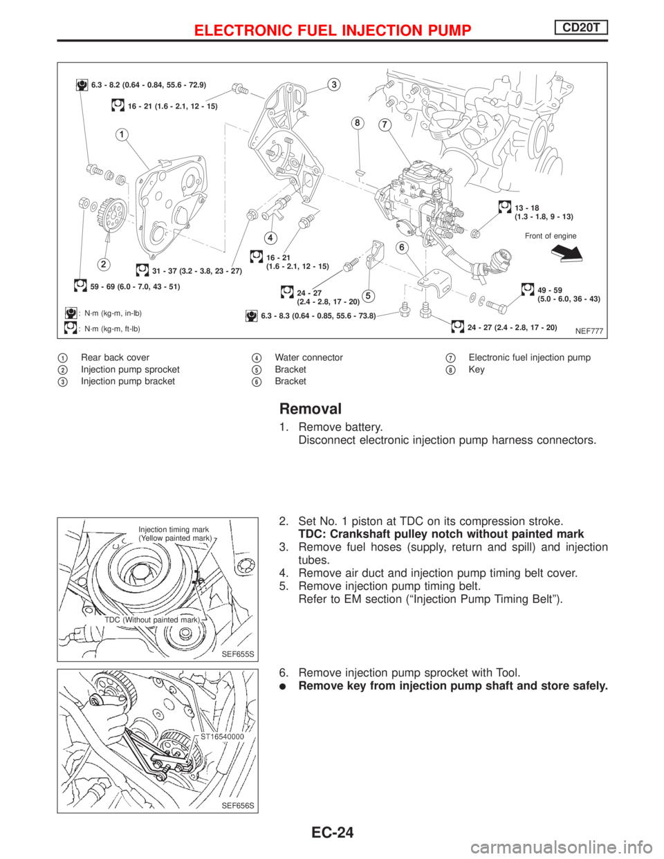
p1Rear back cover
p2Injection pump sprocket
p3Injection pump bracket
p4Water connector
p5Bracket
p6Bracket
p7Electronic fuel injection pump
p8Key
Removal
1. Remove battery.
Disconnect electronic injection pump harness connectors.
2. Set No. 1 piston at TDC on its compression stroke.
TDC: Crankshaft pulley notch without painted mark
3. Remove fuel hoses (supply, return and spill) and injection
tubes.
4. Remove air duct and injection pump timing belt cover.
5. Remove injection pump timing belt.
Refer to EM section (ªInjection Pump Timing Beltº).
6. Remove injection pump sprocket with Tool.
lRemove key from injection pump shaft and store safely.
NEF777
6.3 - 8.2 (0.64 - 0.84, 55.6 - 72.9)
59 - 69 (6.0 - 7.0, 43 - 51)
31 - 37 (3.2 - 3.8, 23 - 27)
: N´m (kg-m, in-lb)
: N´m (kg-m, ft-lb)
16 - 21 (1.6 - 2.1, 12 - 15)
16-21
(1.6 - 2.1, 12 - 15)
24-27
(2.4 - 2.8, 17 - 20)
6.3 - 8.3 (0.64 - 0.85, 55.6 - 73.8)
13-18
(1.3 - 1.8, 9 - 13)
49-59
(5.0 - 6.0, 36 - 43)
24 - 27 (2.4 - 2.8, 17 - 20)Front of engine
SEF655S Injection timing mark
(Yellow painted mark)
TDC (Without painted mark)
SEF656S
ELECTRONIC FUEL INJECTION PUMPCD20T
EC-24
Page 319 of 2267
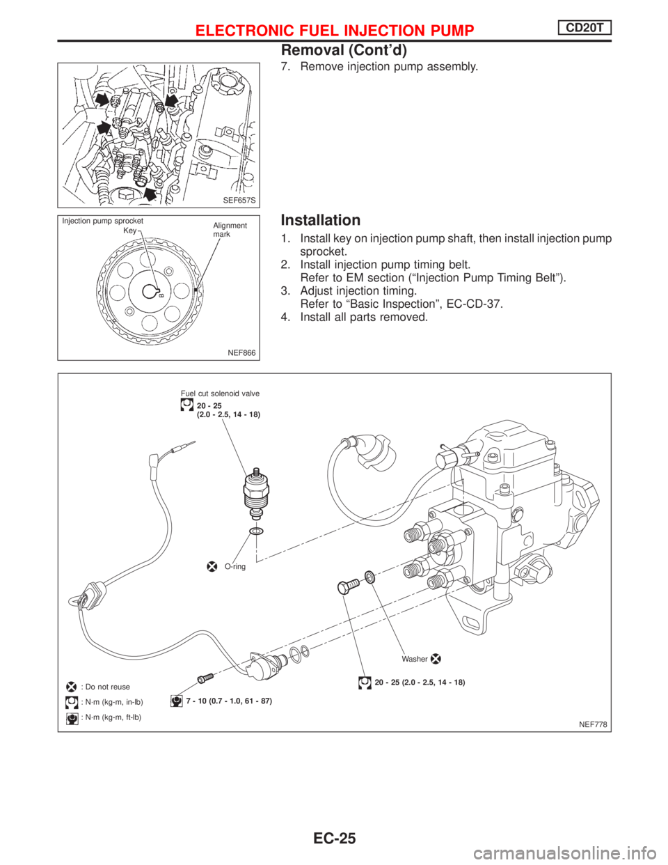
7. Remove injection pump assembly.
Installation
1. Install key on injection pump shaft, then install injection pump
sprocket.
2. Install injection pump timing belt.
Refer to EM section (ªInjection Pump Timing Beltº).
3. Adjust injection timing.
Refer to ªBasic Inspectionº, EC-CD-37.
4. Install all parts removed.
SEF657S
NEF866 Injection pump sprocket
KeyAlignment
mark
NEF778 Fuel cut solenoid valve
20-25
(2.0 - 2.5, 14 - 18)
O-ring
7 - 10 (0.7 - 1.0, 61 - 87)
20 - 25 (2.0 - 2.5, 14 - 18)Washer: Do not reuse
: N´m (kg-m, in-lb)
: N´m (kg-m, ft-lb)
ELECTRONIC FUEL INJECTION PUMPCD20T
Removal (Cont'd)
EC-25
Page 320 of 2267
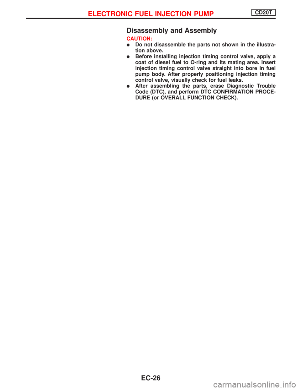
Disassembly and Assembly
CAUTION:
lDo not disassemble the parts not shown in the illustra-
tion above.
lBefore installing injection timing control valve, apply a
coat of diesel fuel to O-ring and its mating area. Insert
injection timing control valve straight into bore in fuel
pump body. After properly positioning injection timing
control valve, visually check for fuel leaks.
lAfter assembling the parts, erase Diagnostic Trouble
Code (DTC), and perform DTC CONFIRMATION PROCE-
DURE (or OVERALL FUNCTION CHECK).
ELECTRONIC FUEL INJECTION PUMPCD20T
EC-26
Page 322 of 2267
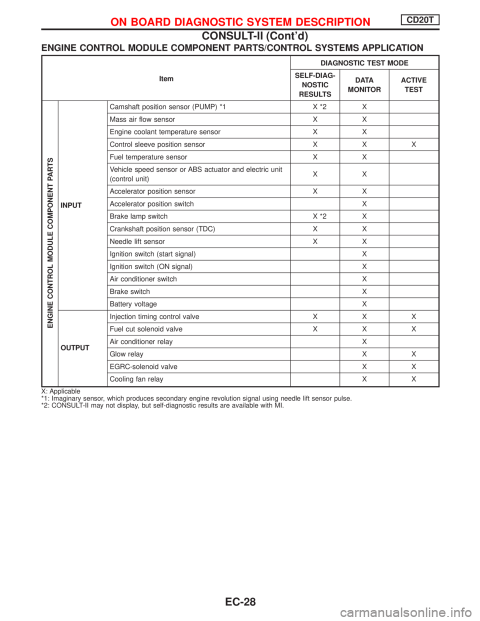
ENGINE CONTROL MODULE COMPONENT PARTS/CONTROL SYSTEMS APPLICATION
ItemDIAGNOSTIC TEST MODE
SELF-DIAG-
NOSTIC
RESULTSD ATA
MONITORACTIVE
TEST
ENGINE CONTROL MODULE COMPONENT PARTS
INPUTCamshaft position sensor (PUMP) *1 X *2 X
Mass air flow sensor X X
Engine coolant temperature sensor X X
Control sleeve position sensor X X X
Fuel temperature sensor X X
Vehicle speed sensor or ABS actuator and electric unit
(control unit)XX
Accelerator position sensor X X
Accelerator position switch X
Brake lamp switch X *2 X
Crankshaft position sensor (TDC) X X
Needle lift sensor X X
Ignition switch (start signal) X
Ignition switch (ON signal) X
Air conditioner switch X
Brake switch X
Battery voltage X
OUTPUTInjection timing control valve X X X
Fuel cut solenoid valve X X X
Air conditioner relay X
Glow relay X X
EGRC-solenoid valve X X
Cooling fan relay X X
X: Applicable
*1: Imaginary sensor, which produces secondary engine revolution signal using needle lift sensor pulse.
*2: CONSULT-II may not display, but self-diagnostic results are available with MI.
ON BOARD DIAGNOSTIC SYSTEM DESCRIPTIONCD20T
CONSULT-II (Cont'd)
EC-28