1999 NISSAN PRIMERA turn signal
[x] Cancel search: turn signalPage 8 of 2267
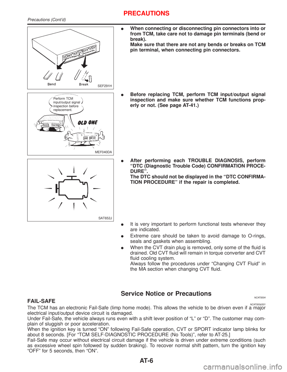
IWhen connecting or disconnecting pin connectors into or
from TCM, take care not to damage pin terminals (bend or
break).
Make sure that there are not any bends or breaks on TCM
pin terminal, when connecting pin connectors.
IBefore replacing TCM, perform TCM input/output signal
inspection and make sure whether TCM functions prop-
erly or not. (See page AT-41.)
IAfter performing each TROUBLE DIAGNOSIS, perform
ªDTC (Diagnostic Trouble Code) CONFIRMATION PROCE-
DUREº.
The DTC should not be displayed in the ªDTC CONFIRMA-
TION PROCEDUREº if the repair is completed.
IIt is very important to perform functional tests whenever they
are indicated.
IExtreme care should be taken to avoid damage to O-rings,
seals and gaskets when assembling.
IWhen the CVT drain plug is removed, only some of the fluid is
drained. Old CVT fluid will remain in torque converter and CVT
fluid cooling system.
Always follow the procedures under ªChanging CVT Fluidº in
the MA section when changing CVT fluid.
Service Notice or PrecautionsNCAT0004FAIL-SAFENCAT0004S01The TCM has an electronic Fail-Safe (limp home mode). This allows the vehicle to be driven even if a major
electrical input/output device circuit is damaged.
Under Fail-Safe, the vehicle always runs even with a shift lever position of ªLº or ªDº. The customer may com-
plain of sluggish or poor acceleration.
When the ignition key is turned ªONº following Fail-Safe operation, CVT or SPORT indicator lamp blinks for
about 8 seconds. [For ªTCM SELF-DIAGNOSTIC PROCEDURE (No Tools)º, refer to AT-25.]
Fail-Safe may occur without electrical circuit damage if the vehicle is driven under extreme conditions (such
as excessive wheel spin followed by sudden braking). To recover normal shift pattern, turn the ignition key
ªOFFº for 5 seconds, then ªONº.
SEF291H
MEF040DA Perform TCM
input/output signal
inspection before
replacement.
SAT652J
PRECAUTIONS
Precautions (Cont'd)
AT-6
Page 17 of 2267
IntroductionNCAT0017The CVT system has two self-diagnostic systems.
The first is the emission-related on board diagnostic system (OBD) performed by the TCM in combination with
the ECM. The malfunction is indicated by the MI (malfunction indicator) and is stored as a DTC in the ECM
memory but not the TCM memory.
The second is the TCM original self-diagnosis indicated by the CVT indicator (warning) lamp or SPORT indi-
cator lamp. The malfunction is stored in the TCM memory. The detected items are overlapped with OBD self-
diagnostic items. For detail, refer to AT-26.
OBD Function for CVT SystemNCAT0018The ECM provides emission-related on board diagnostic (OBD) functions for the CVT system. One function
is to receive a signal from the TCM used with OBD-related parts of the CVT system. The signal is sent to the
ECM when a malfunction occurs in the corresponding OBD-related part. The other function is to indicate a
diagnostic result by means of the MI (malfunction indicator) on the instrument panel. Sensors, switches and
solenoid valves are used as sensing elements.
The MI automatically illuminates in Two Trip Detection Logic when a malfunction is sensed in relation to CVT
system parts.
OBD Diagnostic Trouble Code (DTC)NCAT0020HOW TO READ DTC AND 1ST TRIP DTCNCAT0020S01DTC and 1st trip DTC can be read by the following methods.
1.(
No Tools)The number of blinks of the malfunction indicator in the Diagnostic Test Mode II (Self-Di-
agnostic Results) Examples: 0705, 0710, 0715, 0720, etc. For details, refer to EC section [ªMalfunction
Indicator (MI)º, ªON BOARD DIAGNOSTIC SYSTEM DESCRIPTIONº].
These DTCs are controlled by NISSAN.
2.(
with CONSULT-II orGST)CONSULT-II or GST (Generic Scan Tool) Examples: P0705, P0710,
P0720, P0725, etc.
These DTCs are prescribed by ISO15031-6.
(CONSULT-II also displays the malfunctioning component or system.)
I1st trip DTC No. is the same as DTC No.
IOutput of the diagnostic trouble code indicates that the indicated circuit has a malfunction.
However, in case of the Mode II and GST they do not indicate whether the malfunction is still
occurring or occurred in the past and returned to normal.
CONSULT-II can identify them as shown below. Therefore, using CONSULT-II (if available) is rec-
ommended.
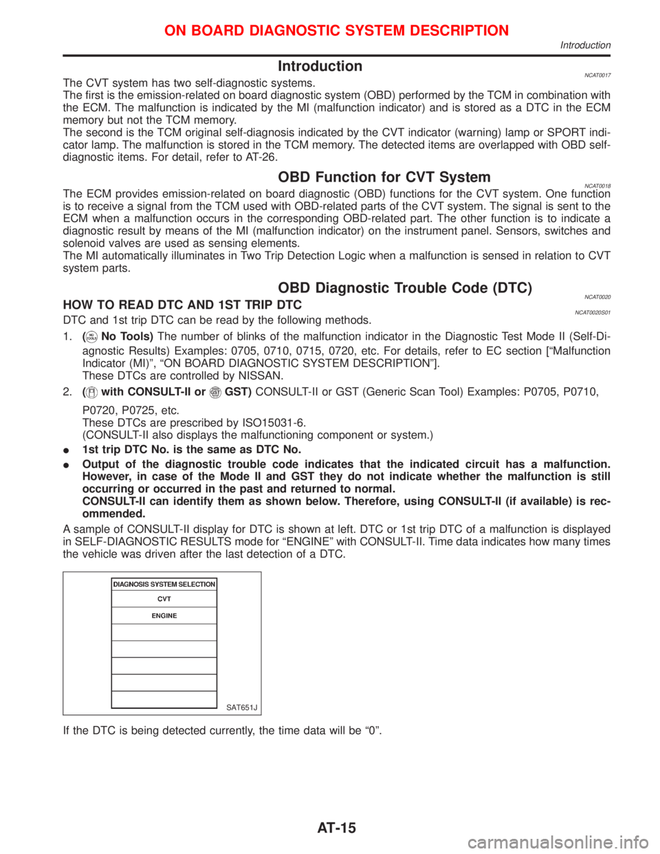
A sample of CONSULT-II display for DTC is shown at left. DTC or 1st trip DTC of a malfunction is displayed
in SELF-DIAGNOSTIC RESULTS mode for ªENGINEº with CONSULT-II. Time data indicates how many times
the vehicle was driven after the last detection of a DTC.
If the DTC is being detected currently, the time data will be ª0º.
SAT651J
ON BOARD DIAGNOSTIC SYSTEM DESCRIPTION
Introduction
AT-15
Page 21 of 2267
SELF-DIAGNOSTIC PROCEDURE
(WITH CONSULT-II)
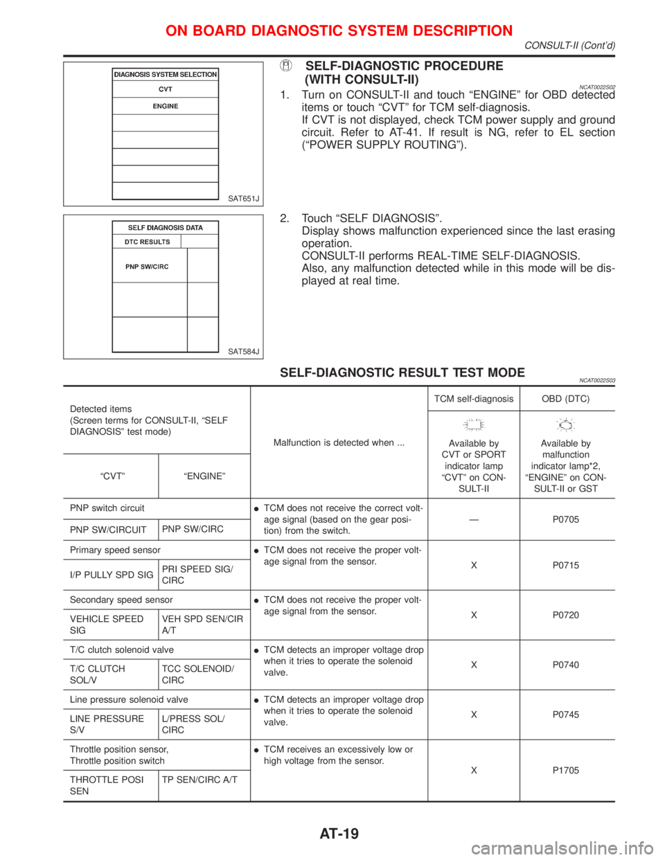
NCAT0022S021. Turn on CONSULT-II and touch ªENGINEº for OBD detected
items or touch ªCVTº for TCM self-diagnosis.
If CVT is not displayed, check TCM power supply and ground
circuit. Refer to AT-41. If result is NG, refer to EL section
(ªPOWER SUPPLY ROUTINGº).
2. Touch ªSELF DIAGNOSISº.
Display shows malfunction experienced since the last erasing
operation.
CONSULT-II performs REAL-TIME SELF-DIAGNOSIS.
Also, any malfunction detected while in this mode will be dis-
played at real time.
SELF-DIAGNOSTIC RESULT TEST MODENCAT0022S03
Detected items
(Screen terms for CONSULT-II, ªSELF
DIAGNOSISº test mode)
Malfunction is detected when ...TCM self-diagnosis OBD (DTC)
Available by
CVT or SPORT
indicator lamp
ªCVTº on CON-
SULT-IIAvailable by
malfunction
indicator lamp*2,
ªENGINEº on CON-
SULT-II or GST ªCVTº ªENGINEº
PNP switch circuitITCM does not receive the correct volt-
age signal (based on the gear posi-
tion) from the switch.Ð P0705
PNP SW/CIRCUITPNP SW/CIRC
Primary speed sensorITCM does not receive the proper volt-
age signal from the sensor.
X P0715
I/P PULLY SPD SIGPRI SPEED SIG/
CIRC
Secondary speed sensorITCM does not receive the proper volt-
age signal from the sensor.
X P0720
VEHICLE SPEED
SIGVEH SPD SEN/CIR
A/T
T/C clutch solenoid valveITCM detects an improper voltage drop
when it tries to operate the solenoid
valve.X P0740
T/C CLUTCH
SOL/VTCC SOLENOID/
CIRC
Line pressure solenoid valveITCM detects an improper voltage drop
when it tries to operate the solenoid
valve.X P0745
LINE PRESSURE
S/VL/PRESS SOL/
CIRC
Throttle position sensor,
Throttle position switchITCM receives an excessively low or
high voltage from the sensor.
X P1705
THROTTLE POSI
SENTP SEN/CIRC A/T
SAT651J
SAT584J
ON BOARD DIAGNOSTIC SYSTEM DESCRIPTION
CONSULT-II (Cont'd)
AT-19
Page 40 of 2267
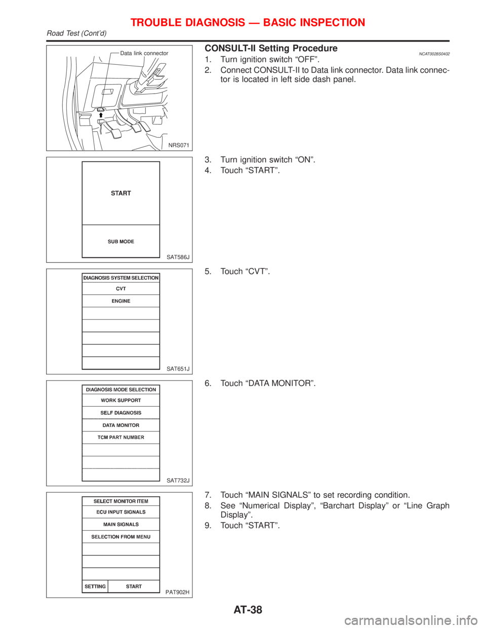
CONSULT-II Setting ProcedureNCAT0028S04021. Turn ignition switch ªOFFº.
2. Connect CONSULT-II to Data link connector. Data link connec-
tor is located in left side dash panel.
3. Turn ignition switch ªONº.
4. Touch ªSTARTº.
5. Touch ªCVTº.
6. Touch ªDATA MONITORº.
7. Touch ªMAIN SIGNALSº to set recording condition.
8. See ªNumerical Displayº, ªBarchart Displayº or ªLine Graph
Displayº.
9. Touch ªSTARTº.
NRS071 Data link connector
SAT586J
SAT651J
SAT732J
PAT902H
TROUBLE DIAGNOSIS Ð BASIC INSPECTION
Road Test (Cont'd)
AT-38
Page 45 of 2267
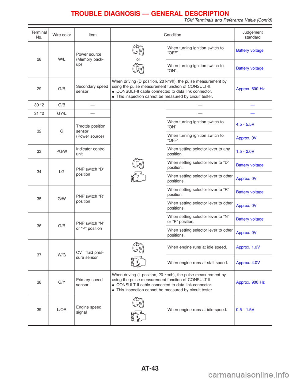
Terminal
No.Wire color Item ConditionJudgement
standard
28 W/LPower source
(Memory back-
up)
or
When turning ignition switch to
ªOFFº.Battery voltage
When turning ignition switch to
ªONº.Battery voltage
29 G/RSecondary speed
sensorWhen driving (D position, 20 km/h), the pulse measurement by
using the pulse measurement function of CONSULT-II.
ICONSULT-II cable connected to data link connector.
IThis inspection cannot be measured by circuit tester.Approx. 600 Hz
30 *2 G/B Ð
ÐÐ
31 *2 GY/L Ð ÐÐ
32 GThrottle position
sensor
(Power source)When turning ignition switch to
ªONº4.5 - 5.5V
When turning ignition switch to
ªOFFºApprox. 0V
33 PU/WIndicator control
unitWhen setting selector lever to any
position.1.5 - 2.0V
34 LGPNP switch ªDº
positionWhen setting selector lever to ªDº
position.Battery voltage
When setting selector lever to other
positions.Approx. 0V
35 G/WPNP switch ªRº
positionWhen setting selector lever to ªRº
position.Battery voltage
When setting selector lever to other
positions.Approx. 0V
36 G/RPNP switch ªNº
or ªPº positionWhen setting selector lever to ªNº
or ªPº position.Battery voltage
When setting selector lever to other
positions.Approx. 0V
37 W/GCVT fluid pres-
sure sensor
When engine runs at idle speed.Approx. 1.0V
When engine runs at stall speed.Approx. 4.0V
38 G/YPrimary speed
sensorWhen driving (L position, 20 km/h), the pulse measurement by
using the pulse measurement function of CONSULT-II.
ICONSULT-II cable connected to data link connector.
IThis inspection cannot be measured by circuit tester.Approx. 900 Hz
39 L/OREngine speed
signal
When engine runs at idle speed.0.5 - 1.5V
TROUBLE DIAGNOSIS Ð GENERAL DESCRIPTION
TCM Terminals and Reference Value (Cont'd)
AT-43
Page 53 of 2267
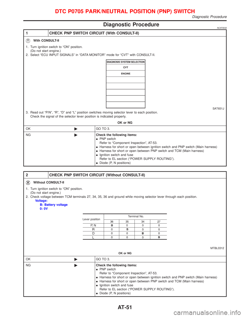
Diagnostic ProcedureNCAT0033
1 CHECK PNP SWITCH CIRCUIT (With CONSULT-II)
With CONSULT-II
1. Turn ignition switch to ªONº position.
(Do not start engine.)
2. Select ªECU INPUT SIGNALSº in ªDATA MONITORº mode for ªCVTº with CONSULT-II.
SAT651J3. Read out ªP/Nº, ªRº, ªDº and ªLº position switches moving selector lever to each position.
Check the signal of the selector lever position is indicated properly.
OK or NG
OK©GO TO 3.
NG©Check the following items:
IPNP switch
Refer to ªComponent Inspectionº, AT-53.
IHarness for short or open between ignition switch and PNP switch (Main harness)
IHarness for short or open between PNP switch and TCM (Main harness)
IIgnition switch and fuse
Refer to EL section (ªPOWER SUPPLY ROUTINGº).
IDiode (P, N positions)
2 CHECK PNP SWITCH CIRCUIT (Without CONSULT-II)
Without CONSULT-II
1. Turn ignition switch to ªONº position.
(Do not start engine.)
2. Check voltage between TCM terminals 27, 34, 35, 36 and ground while moving selector lever through each position.
Voltage:
B: Battery voltage
0: 0V
MTBL0312 Terminal No.
Lever position
OK or NG
OK©GO TO 3.
NG©Check the following items:
IPNP switch
Refer to ªComponent Inspectionº, AT-53.
IHarness for short or open between ignition switch and PNP switch (Main harness)
IHarness for short or open between PNP switch and TCM (Main harness)
IIgnition switch and fuse
Refer to EL section (ªPOWER SUPPLY ROUTINGº).
IDiode (P, N positions)
DTC P0705 PARK/NEUTRAL POSITION (PNP) SWITCH
Diagnostic Procedure
AT-51
Page 59 of 2267
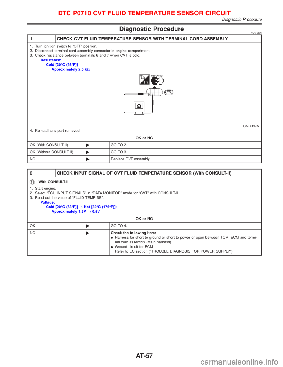
Diagnostic ProcedureNCAT0036
1 CHECK CVT FLUID TEMPERATURE SENSOR WITH TERMINAL CORD ASSEMBLY
1. Turn ignition switch to ªOFFº position.
2. Disconnect terminal cord assembly connector in engine compartment.
3. Check resistance between terminals 6 and 7 when CVT is cold.
Resistance:
Cold [20ÉC (68ÉF)]
Approximately 2.5 kW
SAT419JA4. Reinstall any part removed.
OK or NG
OK (With CONSULT-II)©GO TO 2.
OK (Without CONSULT-II)©GO TO 3.
NG©Replace CVT assembly
2 CHECK INPUT SIGNAL OF CVT FLUID TEMPERATURE SENSOR (With CONSULT-II)
With CONSULT-II
1. Start engine.
2. Select ªECU INPUT SIGNALSº in ªDATA MONITORº mode for ªCVTº with CONSULT-II.
3. Read out the value of ªFLUID TEMP SEº.
Voltage:
Cold [20ÉC (68ÉF)]®Hot [80ÉC (176ÉF)]:
Approximately 1.5V®0.5V
OK or NG
OK©GO TO 4.
NG©Check the following item:
IHarness for short to ground or short to power or open between TCM, ECM and termi-
nal cord assembly (Main harness)
IGround circuit for ECM
Refer to EC section (ªTROUBLE DIAGNOSIS FOR POWER SUPPLYº).
DTC P0710 CVT FLUID TEMPERATURE SENSOR CIRCUIT
Diagnostic Procedure
AT-57
Page 60 of 2267
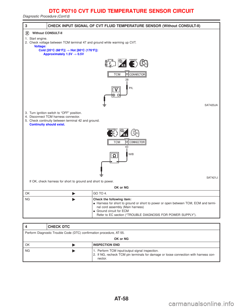
3 CHECK INPUT SIGNAL OF CVT FLUID TEMPERATURE SENSOR (Without CONSULT-II)
Without CONSULT-II
1. Start engine.
2. Check voltage between TCM terminal 47 and ground while warming up CVT.
Voltage:
Cold [20ÉC (68ÉF)]®Hot [80ÉC (176ÉF)]:
Approximately 1.5V®0.5V
SAT420JA
3. Turn ignition switch to ªOFFº position.
4. Disconnect TCM harness connector.
5. Check continuity between terminal 42 and ground.
Continuity should exist.
SAT421JIf OK, check harness for short to ground and short to power.
OK or NG
OK©GO TO 4.
NG©Check the following item:
IHarness for short to ground or short to power or open between TCM, ECM and termi-
nal cord assembly (Main harness)
IGround circuit for ECM
Refer to EC section (ªTROUBLE DIAGNOSIS FOR POWER SUPPLYº).
4 CHECK DTC
Perform Diagnostic Trouble Code (DTC) confirmation procedure, AT-55.
OK or NG
OK©INSPECTION END
NG©1. Perform TCM input/output signal inspection.
2. If NG, recheck TCM pin terminals for damage or loose connection with harness con-
nector.
DTC P0710 CVT FLUID TEMPERATURE SENSOR CIRCUIT
Diagnostic Procedure (Cont'd)
AT-58