1999 NISSAN PRIMERA engine coolant
[x] Cancel search: engine coolantPage 18 of 2267
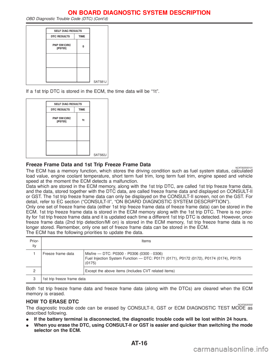
If a 1st trip DTC is stored in the ECM, the time data will be ª1tº.
Freeze Frame Data and 1st Trip Freeze Frame DataNCAT0020S0101The ECM has a memory function, which stores the driving condition such as fuel system status, calculated
load value, engine coolant temperature, short term fuel trim, long term fuel trim, engine speed and vehicle
speed at the moment the ECM detects a malfunction.
Data which are stored in the ECM memory, along with the 1st trip DTC, are called 1st trip freeze frame data,
and the data, stored together with the DTC data, are called freeze frame data and displayed on CONSULT-II
or GST. The 1st trip freeze frame data can only be displayed on the CONSULT-II screen, not on the GST. For
detail, refer to EC section (ªCONSULT-IIº, ªON BOARD DIAGNOSTIC SYSTEM DESCRIPTIONº).
Only one set of freeze frame data (either 1st trip freeze frame data of freeze frame data) can be stored in the
ECM. 1st trip freeze frame data is stored in the ECM memory along with the 1st trip DTC. There is no prior-
ity for 1st trip freeze frame data and it is updated each time a different 1st trip DTC is detected. However, once
freeze frame data (2nd trip detection/MI on) is stored in the ECM memory, 1st trip freeze frame data is no
longer stored. Remember, only one set of freeze frame data can be stored in the ECM.
The ECM has the following priorities to update the data.
Prior-
ityItems
1 Freeze frame data Misfire Ð DTC: P0300 - P0306 (0300 - 0306)
Fuel Injection System Function Ð DTC: P0171 (0171), P0172 (0172), P0174 (0174), P0175
(0175)
2 Except the above items (Includes CVT related items)
3 1st trip freeze frame data
Both 1st trip freeze frame data and freeze frame data (along with the DTCs) are cleared when the ECM
memory is erased.
HOW TO ERASE DTCNCAT0020S02The diagnostic trouble code can be erased by CONSULT-II, GST or ECM DIAGNOSTIC TEST MODE as
described following.
IIf the battery terminal is disconnected, the diagnostic trouble code will be lost within 24 hours.
IWhen you erase the DTC, using CONSULT-II or GST is easier and quicker than switching the mode
selector on the ECM.
SAT581J
SAT582J
ON BOARD DIAGNOSTIC SYSTEM DESCRIPTION
OBD Diagnostic Trouble Code (DTC) (Cont'd)
AT-16
Page 295 of 2267
ENGINE CONTROL SYSTEM
SECTION
EC
CONTENTS
CD20T
PRECAUTIONS AND PREPARATION.......................... 3
Special Service Tools ................................................ 3
Engine Fuel & Emission Control System .................. 5
Supplemental Restraint System (SRS)²AIR
BAG²and²SEAT BELT PRE-TENSIONER²............. 6
Precautions for On Board Diagnostic (OBD)
System of Engine ...................................................... 6
Precautions ................................................................ 7
ENGINE AND EMISSION CONTROL OVERALL
SYSTEM......................................................................... 9
Engine Control Module Component Parts
Location ..................................................................... 9
Circuit Diagram ......................................................... 11
System Diagram ...................................................... 12
Vacuum Hose Drawing ............................................ 13
System Chart ........................................................... 14
ENGINE AND EMISSION BASIC CONTROL
SYSTEM DESCRIPTION............................................. 15
Glow Control System ............................................... 15
Fuel Injection System .............................................. 15
Fuel Injection Timing System .................................. 18
Air Conditioning Cut Control .................................... 20
Cooling Fan Control................................................. 20
CRANKCASE VENTILATION SYSTEM...................... 21
Description ............................................................... 21
Blow-by Control Valve ............................................. 21
Ventilation Hose ....................................................... 21
INJECTION NOZZLE................................................... 22
Removal and Installation ......................................... 22
Test and Adjustment ................................................ 22
ELECTRONIC FUEL INJECTION PUMP.................... 24
Removal ................................................................... 24
Installation ................................................................ 25Disassembly and Assembly ..................................... 26
ON BOARD DIAGNOSTIC SYSTEM
DESCRIPTION............................................................. 27
CONSULT-II ............................................................. 27
TROUBLE DIAGNOSIS - INTRODUCTION................ 33
Introduction .............................................................. 33
Diagnostic Worksheet .............................................. 34
TROUBLE DIAGNOSIS - WORK FLOW.................... 35
Work Flow ................................................................ 35
Description for Work Flow ....................................... 36
TROUBLE DIAGNOSIS - BASIC INSPECTION......... 37
Basic Inspection....................................................... 37
TROUBLE DIAGNOSIS - GENERAL
DESCRIPTION............................................................. 39
Diagnostic Trouble Chart ......................................... 39
Symptom Matrix Chart ............................................. 47
CONSULT-II Reference Value in Data Monitor
Mode ........................................................................ 50
Major Sensor Reference Graph in Data Monitor
Mode ........................................................................ 51
ECM Terminals and Reference Value ..................... 52
TROUBLE DIAGNOSIS FOR POWER SUPPLY........ 59
Main Power Supply and Ground Circuit .................. 59
TROUBLE DIAGNOSIS 1............................................ 62
Mass Air Flow Sensor (MAFS) ................................ 62
TROUBLE DIAGNOSIS 2............................................ 66
Engine Coolant Temperature (ECT) Sensor ........... 66
TROUBLE DIAGNOSIS 3............................................ 70
Vehicle Speed Sensor (VSS) .................................. 70
TROUBLE DIAGNOSIS 4............................................ 74
Control Sleeve Position Sensor (CSPS) ................. 74
TROUBLE DIAGNOSIS 5............................................ 78
Electric Governor ..................................................... 78
TROUBLE DIAGNOSIS 6............................................ 82
EC
Page 308 of 2267
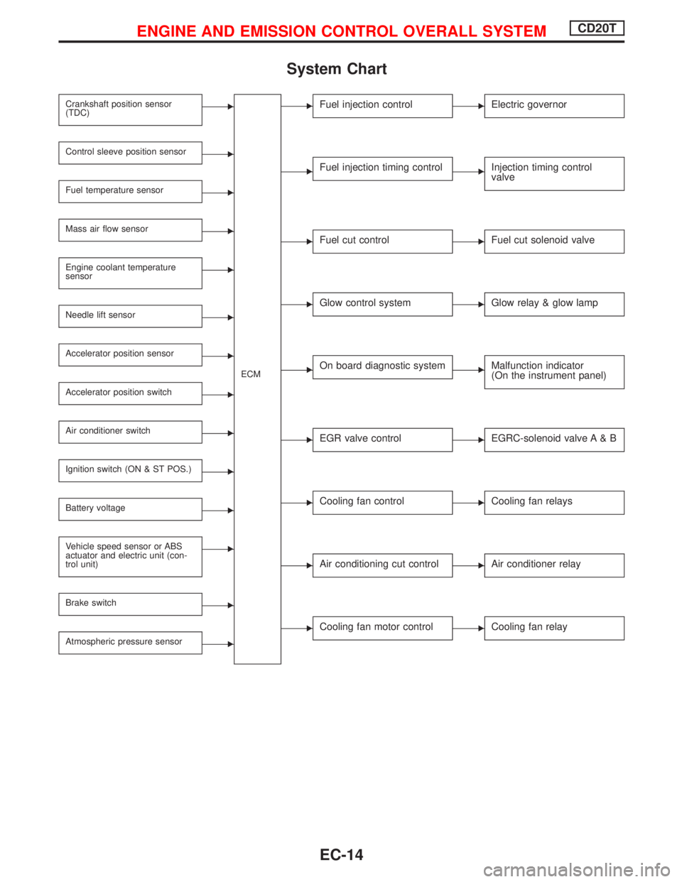
System Chart
Crankshaft position sensor
(TDC)E
ECM
Control sleeve position sensorE
Fuel temperature sensorE
Mass air flow sensorE
Engine coolant temperature
sensorE
Needle lift sensorE
Accelerator position sensorE
Accelerator position switchE
Air conditioner switchE
Ignition switch (ON & ST POS.)E
Battery voltageE
Vehicle speed sensor or ABS
actuator and electric unit (con-
trol unit)E
Brake switchE
Atmospheric pressure sensorE
EFuel injection controlEElectric governor
EFuel injection timing controlEInjection timing control
valve
EFuel cut controlEFuel cut solenoid valve
EGlow control systemEGlow relay & glow lamp
EOn board diagnostic systemEMalfunction indicator
(On the instrument panel)
EEGR valve controlEEGRC-solenoid valve A & B
ECooling fan controlECooling fan relays
EAir conditioning cut controlEAir conditioner relay
ECooling fan motor controlECooling fan relay
ENGINE AND EMISSION CONTROL OVERALL SYSTEMCD20T
EC-14
Page 309 of 2267
Glow Control System
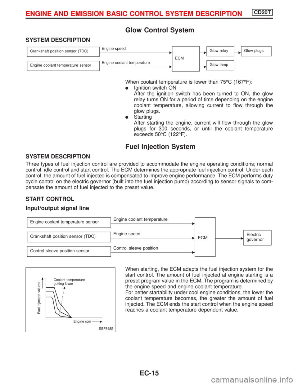
SYSTEM DESCRIPTION
Crankshaft position sensor (TDC)EEngine speed
ECMEGlow relayEGlow plugs
Engine coolant temperature sensorEEngine coolant temperatureEGlow lamp
When coolant temperature is lower than 75ÉC (167ÉF):
lIgnition switch ON
After the ignition switch has been turned to ON, the glow
relay turns ON for a period of time depending on the engine
coolant temperature, allowing current to flow through the
glow plugs.
lStarting
After starting the engine, current will flow through the glow
plugs for 300 seconds, or until the coolant temperature
exceeds 50ÉC (122ÉF).
Fuel Injection System
SYSTEM DESCRIPTION
Three types of fuel injection control are provided to accommodate the engine operating conditions; normal
control, idle control and start control. The ECM determines the appropriate fuel injection control. Under each
control, the amount of fuel injected is compensated to improve engine performance. The ECM performs duty
cycle control on the electric governor (built into the fuel injection pump) according to sensor signals to com-
pensate the amount of fuel injected to the preset value.
START CONTROL
Input/output signal line
Engine coolant temperature sensorEEngine coolant temperature
ECM
EElectric
governorCrankshaft position sensor (TDC)EEngine speed
Control sleeve position sensor
EControl sleeve position
When starting, the ECM adapts the fuel injection system for the
start control. The amount of fuel injected at engine starting is a
preset program value in the ECM. The program is determined by
the engine speed and engine coolant temperature.
For better startability under cool engine conditions, the lower the
coolant temperature becomes, the greater the amount of fuel
injected. The ECM ends the start control when the engine speed
reaches a coolant temperature dependent value.
SEF648S Coolant temperature
getting lower
Engine rpm
Fuel injection volume
ENGINE AND EMISSION BASIC CONTROL SYSTEM DESCRIPTIONCD20T
EC-15
Page 310 of 2267
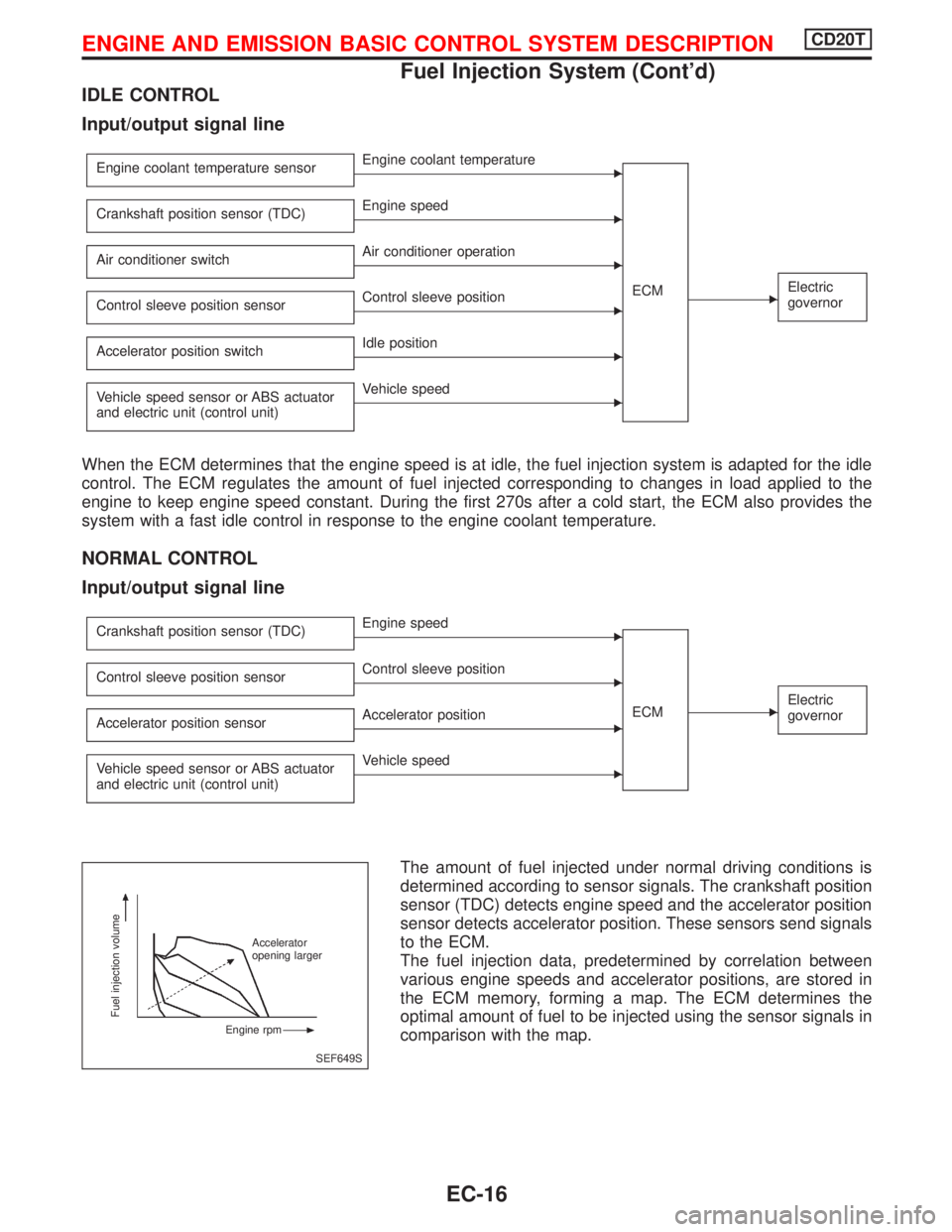
IDLE CONTROL
Input/output signal line
Engine coolant temperature sensorEEngine coolant temperature
ECM
EElectric
governor
Crankshaft position sensor (TDC)EEngine speed
Air conditioner switch
EAir conditioner operation
Control sleeve position sensor
EControl sleeve position
Accelerator position switch
EIdle position
Vehicle speed sensor or ABS actuator
and electric unit (control unit)
EVehicle speed
When the ECM determines that the engine speed is at idle, the fuel injection system is adapted for the idle
control. The ECM regulates the amount of fuel injected corresponding to changes in load applied to the
engine to keep engine speed constant. During the first 270s after a cold start, the ECM also provides the
system with a fast idle control in response to the engine coolant temperature.
NORMAL CONTROL
Input/output signal line
Crankshaft position sensor (TDC)EEngine speed
ECM
EElectric
governor
Control sleeve position sensorEControl sleeve position
Accelerator position sensor
EAccelerator position
Vehicle speed sensor or ABS actuator
and electric unit (control unit)
EVehicle speed
The amount of fuel injected under normal driving conditions is
determined according to sensor signals. The crankshaft position
sensor (TDC) detects engine speed and the accelerator position
sensor detects accelerator position. These sensors send signals
to the ECM.
The fuel injection data, predetermined by correlation between
various engine speeds and accelerator positions, are stored in
the ECM memory, forming a map. The ECM determines the
optimal amount of fuel to be injected using the sensor signals in
comparison with the map.
SEF649S
Fuel injection volume
Accelerator
opening larger
Engine rpm
ENGINE AND EMISSION BASIC CONTROL SYSTEM DESCRIPTIONCD20T
Fuel Injection System (Cont'd)
EC-16
Page 312 of 2267
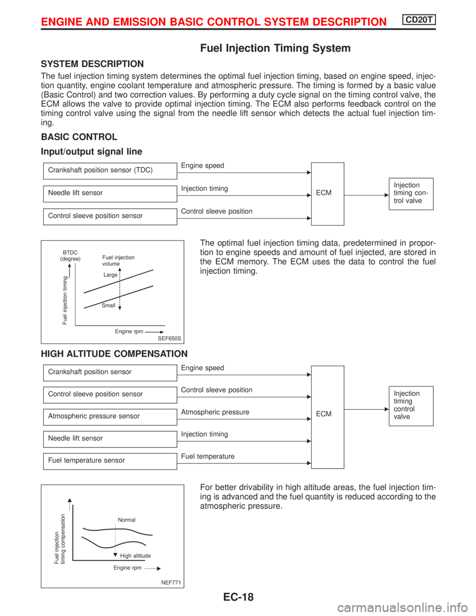
Fuel Injection Timing System
SYSTEM DESCRIPTION
The fuel injection timing system determines the optimal fuel injection timing, based on engine speed, injec-
tion quantity, engine coolant temperature and atmospheric pressure. The timing is formed by a basic value
(Basic Control) and two correction values. By performing a duty cycle signal on the timing control valve, the
ECM allows the valve to provide optimal injection timing. The ECM also performs feedback control on the
timing control valve using the signal from the needle lift sensor which detects the actual fuel injection tim-
ing.
BASIC CONTROL
Input/output signal line
Crankshaft position sensor (TDC)EEngine speed
ECM
E
Injection
timing con-
trol valveNeedle lift sensorEInjection timing
Control sleeve position sensor
EControl sleeve position
The optimal fuel injection timing data, predetermined in propor-
tion to engine speeds and amount of fuel injected, are stored in
the ECM memory. The ECM uses the data to control the fuel
injection timing.
HIGH ALTITUDE COMPENSATION
Crankshaft position sensorEEngine speed
ECM
E
Injection
timing
control
valveControl sleeve position sensorEControl sleeve position
Atmospheric pressure sensor
EAtmospheric pressure
Needle lift sensor
EInjection timing
Fuel temperature sensor
EFuel temperature
For better drivability in high altitude areas, the fuel injection tim-
ing is advanced and the fuel quantity is reduced according to the
atmospheric pressure.
SEF650S
Fuel injection timing
BTDC
(degree)Fuel injection
volume
Large
Small
Engine rpm
NEF771
Fuel injection
timing compensation
Normal
High altitude
Engine rpm
ENGINE AND EMISSION BASIC CONTROL SYSTEM DESCRIPTIONCD20T
EC-18
Page 313 of 2267
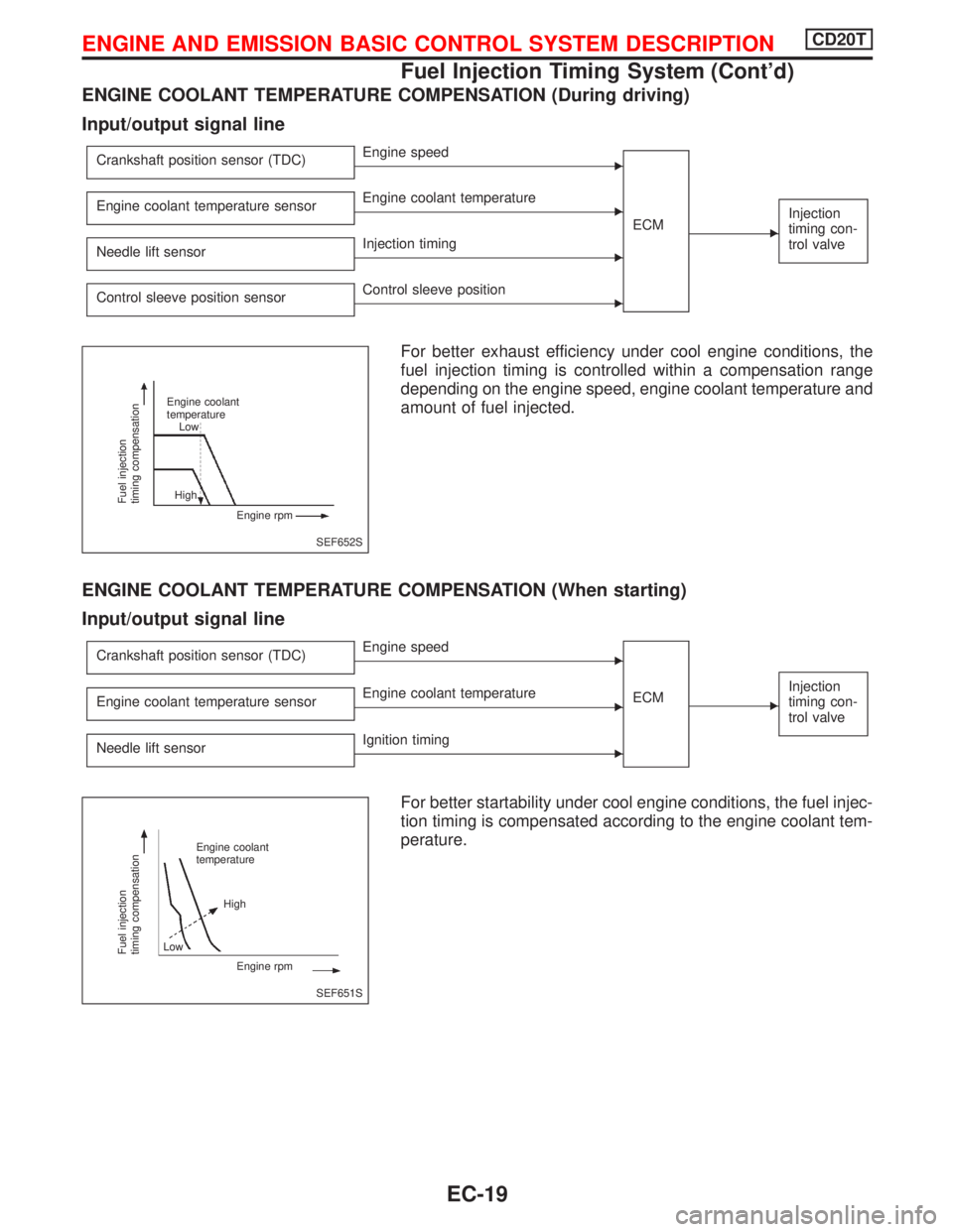
ENGINE COOLANT TEMPERATURE COMPENSATION (During driving)
Input/output signal line
Crankshaft position sensor (TDC)EEngine speed
ECM
E
Injection
timing con-
trol valveEngine coolant temperature sensorEEngine coolant temperature
Needle lift sensor
EInjection timing
Control sleeve position sensor
EControl sleeve position
For better exhaust efficiency under cool engine conditions, the
fuel injection timing is controlled within a compensation range
depending on the engine speed, engine coolant temperature and
amount of fuel injected.
ENGINE COOLANT TEMPERATURE COMPENSATION (When starting)
Input/output signal line
Crankshaft position sensor (TDC)EEngine speed
ECM
E
Injection
timing con-
trol valveEngine coolant temperature sensorEEngine coolant temperature
Needle lift sensor
EIgnition timing
For better startability under cool engine conditions, the fuel injec-
tion timing is compensated according to the engine coolant tem-
perature.
SEF652S
Fuel injection
timing compensation
Engine coolant
temperature
Low
High
Engine rpm
SEF651S
Fuel injection
timing compensation
Engine coolant
temperature
High
Engine rpm Low
ENGINE AND EMISSION BASIC CONTROL SYSTEM DESCRIPTIONCD20T
Fuel Injection Timing System (Cont'd)
EC-19
Page 314 of 2267
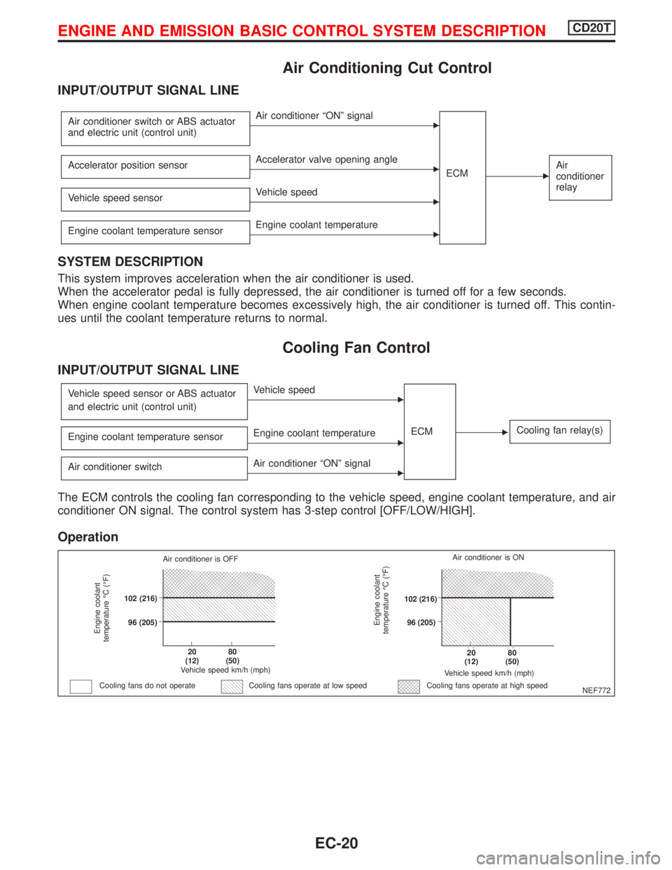
Air Conditioning Cut Control
INPUT/OUTPUT SIGNAL LINE
Air conditioner switch or ABS actuator
and electric unit (control unit)EAir conditioner ªONº signal
ECM
EAir
conditioner
relayAccelerator position sensorEAccelerator valve opening angle
Vehicle speed sensor
EVehicle speed
Engine coolant temperature sensor
EEngine coolant temperature
SYSTEM DESCRIPTION
This system improves acceleration when the air conditioner is used.
When the accelerator pedal is fully depressed, the air conditioner is turned off for a few seconds.
When engine coolant temperature becomes excessively high, the air conditioner is turned off. This contin-
ues until the coolant temperature returns to normal.
Cooling Fan Control
INPUT/OUTPUT SIGNAL LINE
Vehicle speed sensor or ABS actuator
and electric unit (control unit)EVehicle speed
ECM
ECooling fan relay(s)Engine coolant temperature sensorEEngine coolant temperature
Air conditioner switch
EAir conditioner ªONº signal
The ECM controls the cooling fan corresponding to the vehicle speed, engine coolant temperature, and air
conditioner ON signal. The control system has 3-step control [OFF/LOW/HIGH].
Operation
NEF772
Engine coolant
temperature ÉC (ÉF)
Air conditioner is OFF
.102 (216)
.96 (205)
.20
(12).80
(50)
Vehicle speed km/h (mph)
Cooling fans do not operateCooling fans operate at high speed
Engine coolant
temperature ÉC (ÉF)
Vehicle speed km/h (mph)
.20
(12).80
(50)
.102 (216)
.96 (205)Air conditioner is ON
Cooling fans operate at low speed
ENGINE AND EMISSION BASIC CONTROL SYSTEM DESCRIPTIONCD20T
EC-20