1999 NISSAN PRIMERA steering wheel adjustment
[x] Cancel search: steering wheel adjustmentPage 125 of 2267
Supplemental Restraint System (SRS) ªAIR
BAGº and ªSEAT BELT PRE-TENSIONERº
The Supplemental Restraint System such as ªAIR BAGº and ªSEAT BELT PRE-TENSIONERº used along
with a seat belt, helps to reduce the risk or severity of injury to the driver and front passenger for certain
types of collision. The SRS system composition which is available to NISSAN MODEL P11 is as follows (The
composition varies according to the destination and optional equipment.):
lFor a frontal collision
The Supplemental Restraint System consists of driver air bag module (located in the center of the
steering wheel), front passenger air bag module (located on the instrument panel on passenger side),
front seat belt pre-tensioners, a diagnosis sensor unit, warning lamp, wiring harness and spiral cable.
lFor a side collision
The Supplemental Restraint System consists of front side air bag module (located in the outer side of
front seat), side air bag (satellite) sensor, diagnosis sensor unit (one of components of air bags for a
frontal collision), wiring harness, warning lamp (one of components of air bags for a frontal collision).
Information necessary to service the system safely is included in theRS sectionof this Service Manual.
WARNING:
lTo avoid rendering the SRS inoperative, which could increase the risk of personal injury or death
in the event of a collision which would result in air bag inflation, all maintenance should be per-
formed by an authorized NISSAN dealer.
lImproper maintenance, including incorrect removal and installation of the SRS, can lead to per-
sonal injury caused by unintentional activation of the system. For removal of Spiral Cable and
Air Bag Module, see the RS section.
lDo not use electrical test equipment on any circuit related to the SRS unless instructed to in this
Service Manual. Spiral cable and wiring harnesses covered with yellow insulation tape either just
before the harness connectors or for the complete harness are related to the SRS.
Precautions for Brake System
lRecommended fluid is brake fluid ªDOT 4º.
lNever reuse drained brake fluid.
lBe careful not to splash brake fluid on painted areas.
lTo clean or wash all parts of master cylinder, disc brake
caliper and wheel cylinder, use clean brake fluid.
lNever use mineral oils such as gasoline or kerosene.
They will ruin rubber parts of the hydraulic system.
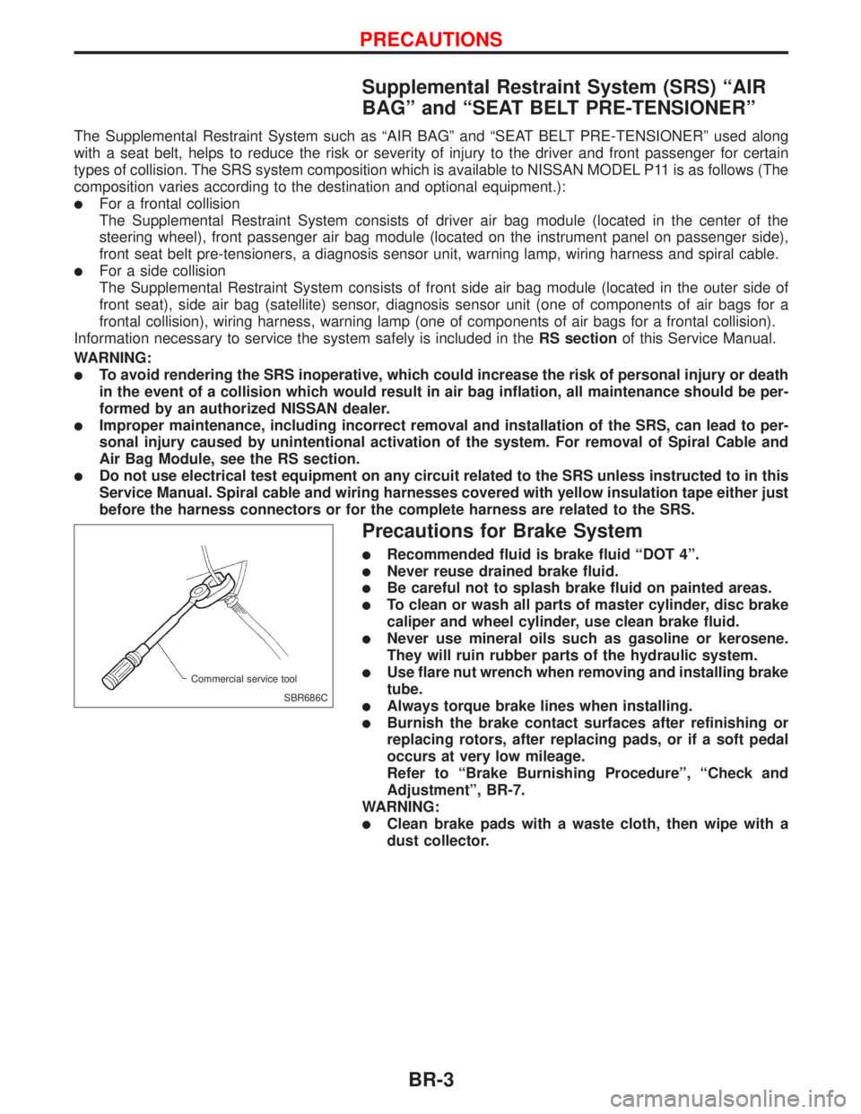
lUse flare nut wrench when removing and installing brake
tube.
lAlways torque brake lines when installing.
lBurnish the brake contact surfaces after refinishing or
replacing rotors, after replacing pads, or if a soft pedal
occurs at very low mileage.
Refer to ªBrake Burnishing Procedureº, ªCheck and
Adjustmentº, BR-7.
WARNING:
lClean brake pads with a waste cloth, then wipe with a
dust collector.
SBR686C Commercial service tool
PRECAUTIONS
BR-3
Page 284 of 2267
INSPECITON
Pedal stroke
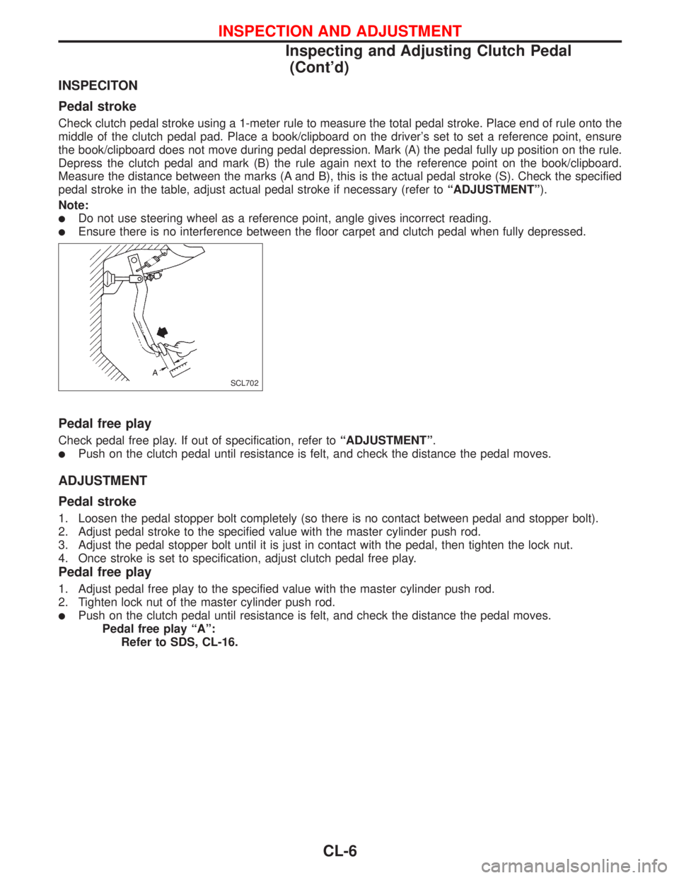
Check clutch pedal stroke using a 1-meter rule to measure the total pedal stroke. Place end of rule onto the
middle of the clutch pedal pad. Place a book/clipboard on the driver's set to set a reference point, ensure
the book/clipboard does not move during pedal depression. Mark (A) the pedal fully up position on the rule.
Depress the clutch pedal and mark (B) the rule again next to the reference point on the book/clipboard.
Measure the distance between the marks (A and B), this is the actual pedal stroke (S). Check the specified
pedal stroke in the table, adjust actual pedal stroke if necessary (refer toªADJUSTMENTº).
Note:
lDo not use steering wheel as a reference point, angle gives incorrect reading.
lEnsure there is no interference between the floor carpet and clutch pedal when fully depressed.
Pedal free play
Check pedal free play. If out of specification, refer toªADJUSTMENTº.
lPush on the clutch pedal until resistance is felt, and check the distance the pedal moves.
ADJUSTMENT
Pedal stroke
1. Loosen the pedal stopper bolt completely (so there is no contact between pedal and stopper bolt).
2. Adjust pedal stroke to the specified value with the master cylinder push rod.
3. Adjust the pedal stopper bolt until it is just in contact with the pedal, then tighten the lock nut.
4. Once stroke is set to specification, adjust clutch pedal free play.
Pedal free play
1. Adjust pedal free play to the specified value with the master cylinder push rod.
2. Tighten lock nut of the master cylinder push rod.
lPush on the clutch pedal until resistance is felt, and check the distance the pedal moves.
Pedal free play ªAº:
Refer to SDS, CL-16.
SCL702
INSPECTION AND ADJUSTMENT
Inspecting and Adjusting Clutch Pedal
(Cont'd)
CL-6
Page 1777 of 2267
Inspection and Adjustment
WHEEL ALIGNMENT (Unladen*1)
Applied model195/60 R15
195/60 VR15
185/65 HR15205/50 R16
Camber Minimum þ0É45¢
Degree minute Nominal 0É
Maximum 0É45¢
Caster Minimum 1É10¢
Degree minute Nominal 1É55¢
Maximum 2É40¢
Kingpin inclination Minimum 13É45¢
Degree minute Nominal 14É30¢
Maximum 15É15¢
Total toe-in Minimum 0 (0)
Distance (A - B) Nominal 1 (0.04)
mm (in) Maximum 2 (0.08)
Angle (left plus right) Minimum 0É
Degree minute Nominal 0É6¢
Maximum 0É12¢
Wheel turning angle Minimum 32 31
Full turn *2 Nominal 35 34
Inside Degree minute Maximum 36 35
Outside Degree minute Nominal 30 29
*1: Fuel, radiator coolant and engine oil full. Spare tire, jack, hand tools and mats in designated positions.
*2: Wheel turning force (at circumference of steering wheel) of 98 to 147 N (10 to 15 kg, 22 to 33 lb) with engine idle.
WHEEL BEARING
Wheel bearing axial end
play limit mm (in)0.05 (0.0020) or less
Wheel bearing lock nut
tightening torque
N´m (kg-m, ft-lb)235 - 314
(24 - 32, 174 - 231)
LOWER BALL JOINT
Ball stud swinging force
at cotter pin hole N (kg, lb)7.8 - 57.9
(0.8 - 5.9, 6 - 42)
Ball stud rotating torque
N´m (kg-cm, in-lb)0.5 - 3.4
(5 - 34, 5 - 30)
Ball stud axial end play
limit mm (in)0 (0)
WHEEL RUNOUT
Wheel type Aluminium Steel
Radial runout limit mm (in) 0.3 (0.012) 0.5 (0.020)
Lateral runout limit mm (in) 0.3 (0.012) 0.8 (0.031)
SERVICE DATA AND SPECIFICATIONS (SDS)
FA-35
Page 1974 of 2267
S/SIG - Wiring diagram ....EC-QG-333, EC-SR-313,
EC-CD-145
Stabilizer bar (front) ........................................FA-32
Stall test (A/T) .................................................AT-34
Standardized relay ............................................EL-8
START - Wiring diagram .................................EL-37
Start signal .................EC-QG-38, 332, EC-SR-312,
EC-CD-145
Starter .......................................................EL-37, 43
Starting system ...............................................EL-37
Steering gear and linkage inspection ............MA-53
Steering knuckle........................................FA-11, 12
Stop lamp ......................................................EL-104
STOP/L - Wiring diagram..............................EL-104
Sun roof, electric ...........................................EL-230
Sunload sensor ..............................................HA-86
Sunroof .....................................................BT-31, 46
Super lock .............................................EL-245, 265
Supplemental Restraint System .......................RS-8
Supplemental restraint system - Wiring
diagram .......................................................RS-33
Symbols and abbreviations .............................GI-38
Symptom matrix chart ...........EC-QG-82, EC-SR-94
Synchronizer (M/T) ......................MT-22, 27, 59, 65
System readiness test (SRT) code ..........EC-SR-50
T
Tachometer ...........................................EL-141, 146
Tail lamp ........................................................EL-100
TCM circuit diagram ........................................AT-10
TCM inspection table ......................................AT-41
Temperature control cable and linkage
adjustment ..................................................HA-83
THEFT - Wiring diagram ...............................EL-316
Theft warning system ....................................EL-311
Thermal protector .........................................HA-113
Thermo control amp .......................................HA-80
Thermostat ..........................................LC-11, 23, 34
Third link (front susp.) .....................................FA-29
Three way catalyst ............EC-QG-258, EC-SR-246
Three way catalyst precautions.........................GI-6
Throttle position sensor
(TPS) .............................EC-QG-125, EC-SR-137
Throttle position sensor
adjustment .........................EC-QG-72, EC-SR-84
Throttle position switch ...............EC-SR-271, AT-85
Tightening torque of standard bolts.................GI-50
Time control system ......................................EL-306
Timing belt....................................................EM-131
Timing chain.............................................EM-19, 75
Tire rotation ....................................................MA-53
Tire size ...........................................................GI-45
Torque converter installation .........................AT-117
Torque convertor clutch solenoid valve...........AT-69
Tow truck towing ..............................................GI-46
Towing point.....................................................GI-49
TP/SW - Wiring diagram ........................EC-SR-273
TPS - Wiring diagram .......EC-QG-128, EC-SR-140
Transmission case (M/T) ................................MT-39Transverse link (front) .....................................FA-32
Trim .................................................................BT-18
Triple pressure switch ....................................HA-79
Trouble diagnoses ...........................................GI-35
Trunk lid ............................................................BT-7
Trunk lid opener - See Trunk lid .......................BT-7
Trunk room lamp...................................EL-130, 131
Trunk room trim...............................................BT-28
Turbocharger........................................EM-156, 201
Turbocharger precautions..................................GI-6
TURN - Wiring diagram.................................EL-118
Turn signal lamp............................................EL-117
Two trip detection logic .........EC-QG-36, EC-SR-48
U
Upper link (front susp.) ...................................FA-29
V
Vacuum hose (brake system).........................BR-20
Vacuum hose drawing (Engine
control) ............EC-QG-19, EC-SR-21, EC-CD-13
Valve clearance .............................EM-40, 179, 191
Valve guide..............EM-36, 93, 142, 180, 189, 197
Valve lifter ..............................EM-40, 145, 179, 198
Valve seat................EM-38, 95, 143, 182, 190, 198
Valve spring.............EM-39, 96, 145, 179, 189, 197
Vehicle identification number...........................GI-43
Vehicle speed sensor
(VSS) ..........EC-QG-267, EC-SR-255, EC-CD-70
Viscosity number (SAE) .................................MA-17
VSS - Wiring
diagram .......EC-QG-269, EC-SR-257, EC-CD-71
W
WARN - Wiring diagram ...............................EL-167
Warning buzzer .............................................EL-180
Warning chime ..............................................EL-180
Warning lamps ..............................................EL-165
Washer, front .................................................EL-186
Washer, rear..................................................EL-193
Water cock control rod adjustment ................HA-82
Water pump ........................................LC-10, 22, 33
Water temperature gauge .....................EL-141, 146
Weatherstrip - See Exterior ............................BT-31
Wheel alignment (front) ..................................FA-35
Wheel alignment (rear).....................................RA-6
Wheel balance ...............................................MA-53
Wheel bearing (front axle) ....................FA-6, 12, 35
Wheel bearing (rear) ........................................RA-5
Wheel hub (front) ............................................FA-12
Wheel hub (rear) ..............................................RA-7
Wheel sensors (ABS) .....................................BR-53
Wheel size .......................................................GI-45
Wheelbase (Dimensions) ................................GI-45
ALPHABETICAL INDEX
IDX-7
Page 2244 of 2267
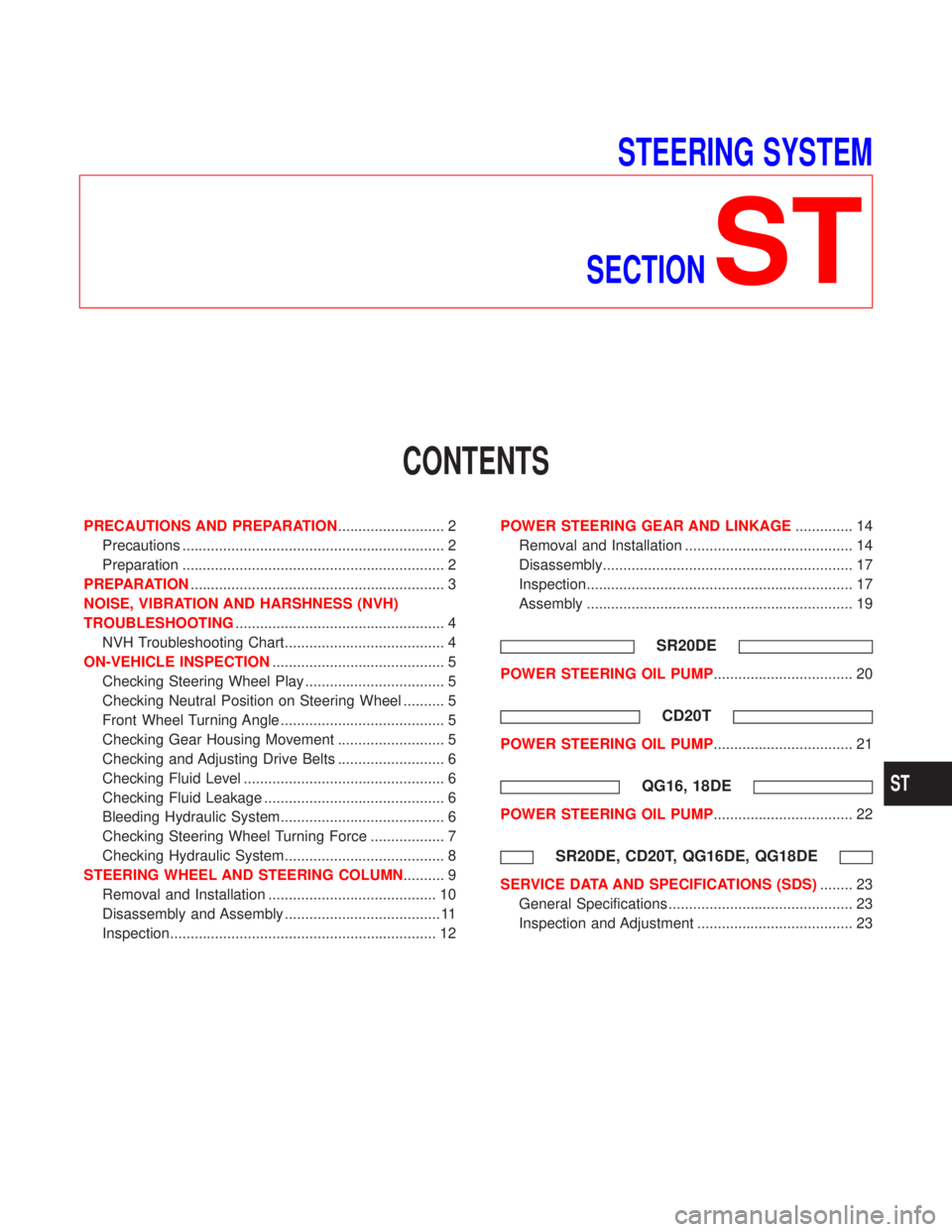
STEERING SYSTEM
SECTION
ST
CONTENTS
PRECAUTIONS AND PREPARATION.......................... 2
Precautions ................................................................ 2
Preparation ................................................................ 2
PREPARATION.............................................................. 3
NOISE, VIBRATION AND HARSHNESS (NVH)
TROUBLESHOOTING................................................... 4
NVH Troubleshooting Chart....................................... 4
ON-VEHICLE INSPECTION.......................................... 5
Checking Steering Wheel Play .................................. 5
Checking Neutral Position on Steering Wheel .......... 5
Front Wheel Turning Angle ........................................ 5
Checking Gear Housing Movement .......................... 5
Checking and Adjusting Drive Belts .......................... 6
Checking Fluid Level ................................................. 6
Checking Fluid Leakage ............................................ 6
Bleeding Hydraulic System........................................ 6
Checking Steering Wheel Turning Force .................. 7
Checking Hydraulic System....................................... 8
STEERING WHEEL AND STEERING COLUMN.......... 9
Removal and Installation ......................................... 10
Disassembly and Assembly ...................................... 11
Inspection................................................................. 12POWER STEERING GEAR AND LINKAGE.............. 14
Removal and Installation ......................................... 14
Disassembly............................................................. 17
Inspection................................................................. 17
Assembly ................................................................. 19
SR20DE
POWER STEERING OIL PUMP.................................. 20
CD20T
POWER STEERING OIL PUMP.................................. 21
QG16, 18DE
POWER STEERING OIL PUMP.................................. 22
SR20DE, CD20T, QG16DE, QG18DE
SERVICE DATA AND SPECIFICATIONS (SDS)........ 23
General Specifications ............................................. 23
Inspection and Adjustment ...................................... 23
ST
Page 2266 of 2267
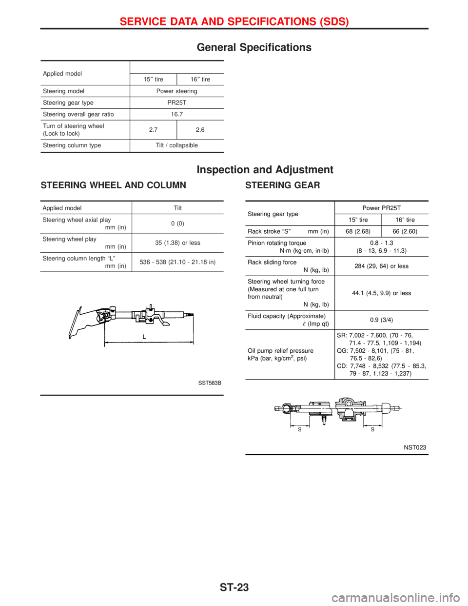
General Specifications
Applied model
15²tire 16²tire
Steering model Power steering
Steering gear type PR25T
Steering overall gear ratio 16.7
Turn of steering wheel
(Lock to lock)2.7 2.6
Steering column type Tilt / collapsible
Inspection and Adjustment
STEERING WHEEL AND COLUMN STEERING GEAR
Applied model Tilt
Steering wheel axial play
mm (in)0 (0)
Steering wheel play
mm (in)35 (1.38) or less
Steering column length ªLº
mm (in)536 - 538 (21.10 - 21.18 in)
SST583B L
Steering gear typePower PR25T
15º tire 16º tire
Rack stroke ªSº mm (in) 68 (2.68) 66 (2.60)
Pinion rotating torque
N´m (kg-cm, in-lb)0.8 - 1.3
(8 - 13, 6.9 - 11.3)
Rack sliding force
N (kg, lb)284 (29, 64) or less
Steering wheel turning force
(Measured at one full turn
from neutral)
N (kg, lb)44.1 (4.5, 9.9) or less
Fluid capacity (Approximate)
(Imp qt)0.9 (3/4)
Oil pump relief pressure
kPa (bar, kg/cm
2, psi)SR: 7,002 - 7,600, (70 - 76,
71.4 - 77.5, 1,109 - 1,194)
QG: 7,502 - 8,101, (75 - 81,
76.5 - 82,6)
CD: 7,748 - 8,532 (77.5 - 85.3,
79 - 87, 1,123 - 1,237)
NST023
SERVICE DATA AND SPECIFICATIONS (SDS)
ST-23