1999 NISSAN PRIMERA timing belt
[x] Cancel search: timing beltPage 295 of 2267
ENGINE CONTROL SYSTEM
SECTION
EC
CONTENTS
CD20T
PRECAUTIONS AND PREPARATION.......................... 3
Special Service Tools ................................................ 3
Engine Fuel & Emission Control System .................. 5
Supplemental Restraint System (SRS)²AIR
BAG²and²SEAT BELT PRE-TENSIONER²............. 6
Precautions for On Board Diagnostic (OBD)
System of Engine ...................................................... 6
Precautions ................................................................ 7
ENGINE AND EMISSION CONTROL OVERALL
SYSTEM......................................................................... 9
Engine Control Module Component Parts
Location ..................................................................... 9
Circuit Diagram ......................................................... 11
System Diagram ...................................................... 12
Vacuum Hose Drawing ............................................ 13
System Chart ........................................................... 14
ENGINE AND EMISSION BASIC CONTROL
SYSTEM DESCRIPTION............................................. 15
Glow Control System ............................................... 15
Fuel Injection System .............................................. 15
Fuel Injection Timing System .................................. 18
Air Conditioning Cut Control .................................... 20
Cooling Fan Control................................................. 20
CRANKCASE VENTILATION SYSTEM...................... 21
Description ............................................................... 21
Blow-by Control Valve ............................................. 21
Ventilation Hose ....................................................... 21
INJECTION NOZZLE................................................... 22
Removal and Installation ......................................... 22
Test and Adjustment ................................................ 22
ELECTRONIC FUEL INJECTION PUMP.................... 24
Removal ................................................................... 24
Installation ................................................................ 25Disassembly and Assembly ..................................... 26
ON BOARD DIAGNOSTIC SYSTEM
DESCRIPTION............................................................. 27
CONSULT-II ............................................................. 27
TROUBLE DIAGNOSIS - INTRODUCTION................ 33
Introduction .............................................................. 33
Diagnostic Worksheet .............................................. 34
TROUBLE DIAGNOSIS - WORK FLOW.................... 35
Work Flow ................................................................ 35
Description for Work Flow ....................................... 36
TROUBLE DIAGNOSIS - BASIC INSPECTION......... 37
Basic Inspection....................................................... 37
TROUBLE DIAGNOSIS - GENERAL
DESCRIPTION............................................................. 39
Diagnostic Trouble Chart ......................................... 39
Symptom Matrix Chart ............................................. 47
CONSULT-II Reference Value in Data Monitor
Mode ........................................................................ 50
Major Sensor Reference Graph in Data Monitor
Mode ........................................................................ 51
ECM Terminals and Reference Value ..................... 52
TROUBLE DIAGNOSIS FOR POWER SUPPLY........ 59
Main Power Supply and Ground Circuit .................. 59
TROUBLE DIAGNOSIS 1............................................ 62
Mass Air Flow Sensor (MAFS) ................................ 62
TROUBLE DIAGNOSIS 2............................................ 66
Engine Coolant Temperature (ECT) Sensor ........... 66
TROUBLE DIAGNOSIS 3............................................ 70
Vehicle Speed Sensor (VSS) .................................. 70
TROUBLE DIAGNOSIS 4............................................ 74
Control Sleeve Position Sensor (CSPS) ................. 74
TROUBLE DIAGNOSIS 5............................................ 78
Electric Governor ..................................................... 78
TROUBLE DIAGNOSIS 6............................................ 82
EC
Page 318 of 2267
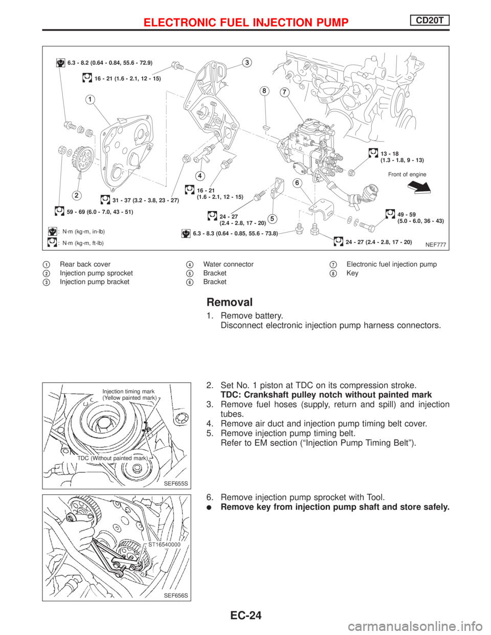
p1Rear back cover
p2Injection pump sprocket
p3Injection pump bracket
p4Water connector
p5Bracket
p6Bracket
p7Electronic fuel injection pump
p8Key
Removal
1. Remove battery.
Disconnect electronic injection pump harness connectors.
2. Set No. 1 piston at TDC on its compression stroke.
TDC: Crankshaft pulley notch without painted mark
3. Remove fuel hoses (supply, return and spill) and injection
tubes.
4. Remove air duct and injection pump timing belt cover.
5. Remove injection pump timing belt.
Refer to EM section (ªInjection Pump Timing Beltº).
6. Remove injection pump sprocket with Tool.
lRemove key from injection pump shaft and store safely.
NEF777
6.3 - 8.2 (0.64 - 0.84, 55.6 - 72.9)
59 - 69 (6.0 - 7.0, 43 - 51)
31 - 37 (3.2 - 3.8, 23 - 27)
: N´m (kg-m, in-lb)
: N´m (kg-m, ft-lb)
16 - 21 (1.6 - 2.1, 12 - 15)
16-21
(1.6 - 2.1, 12 - 15)
24-27
(2.4 - 2.8, 17 - 20)
6.3 - 8.3 (0.64 - 0.85, 55.6 - 73.8)
13-18
(1.3 - 1.8, 9 - 13)
49-59
(5.0 - 6.0, 36 - 43)
24 - 27 (2.4 - 2.8, 17 - 20)Front of engine
SEF655S Injection timing mark
(Yellow painted mark)
TDC (Without painted mark)
SEF656S
ELECTRONIC FUEL INJECTION PUMPCD20T
EC-24
Page 319 of 2267
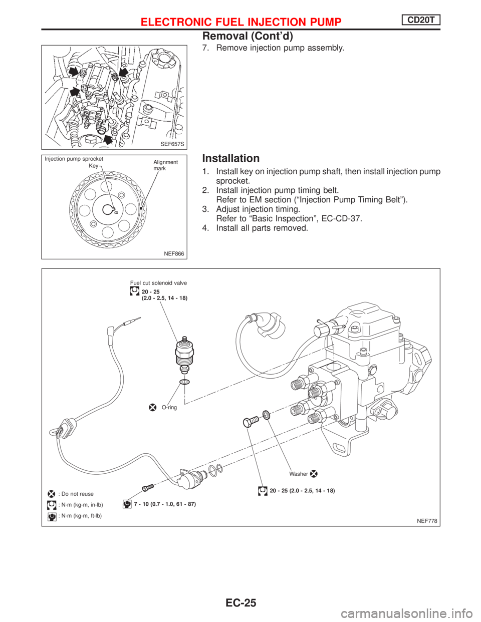
7. Remove injection pump assembly.
Installation
1. Install key on injection pump shaft, then install injection pump
sprocket.
2. Install injection pump timing belt.
Refer to EM section (ªInjection Pump Timing Beltº).
3. Adjust injection timing.
Refer to ªBasic Inspectionº, EC-CD-37.
4. Install all parts removed.
SEF657S
NEF866 Injection pump sprocket
KeyAlignment
mark
NEF778 Fuel cut solenoid valve
20-25
(2.0 - 2.5, 14 - 18)
O-ring
7 - 10 (0.7 - 1.0, 61 - 87)
20 - 25 (2.0 - 2.5, 14 - 18)Washer: Do not reuse
: N´m (kg-m, in-lb)
: N´m (kg-m, ft-lb)
ELECTRONIC FUEL INJECTION PUMPCD20T
Removal (Cont'd)
EC-25
Page 443 of 2267
ENGINE CONTROL SYSTEM
SECTION
EC
CONTENTS
QG16I18DE
TROUBLE DIAGNOSIS - INDEX....................................6
Alphabetical & P No. Index for DTC ...........................6
PRECAUTIONS...............................................................9
Supplemental Restraint System (SRS)²AIR
BAG²and²SEAT BELT PRE-TENSIONER²...............9
Precautions for On Board Diagnostic (OBD)
System of Engine ........................................................9
Engine Fuel & Emission Control System ..................10
Precautions ................................................................ 11
Wiring Diagrams and Trouble Diagnosis ...................12
PREPARATION..............................................................13
Special Service Tools ................................................13
Commercial Service Tool ...........................................13
ENGINE AND EMISSION CONTROL OVERALL
SYSTEM.........................................................................14
Engine Control Component Parts Location ...............14
Circuit Diagram ..........................................................17
System Diagram ........................................................18
Vacuum Hose Drawing ..............................................19
System Chart .............................................................20
ENGINE AND EMISSION BASIC CONTROL
SYSTEM DESCRIPTION...............................................21
Multiport Fuel Injection (MFI) System .......................21
Electronic Ignition (EI) System ..................................23
Air Conditioning Cut Control ......................................24
Fuel Cut Control (at no load & high engine
speed) ........................................................................25
Evaporative Emission System ...................................25
Positive Crankcase Ventilation ..................................28
BASIC SERVICE PROCEDURE...................................29
Fuel Pressure Release ..............................................29
Fuel Pressure Check .................................................29
Fuel Pressure Regulator Check ................................30
Injector .......................................................................30
Idle Speed/Ignition Timing/Idle Mixture Ratio
Adjustment .................................................................32Idle Air Volume Learning ...........................................33
ON BOARD DIAGNOSTIC SYSTEM
DESCRIPTION...............................................................36
Introduction ................................................................36
Two Trip Detection Logic ...........................................36
Emission-related Diagnostic Information ...................37
Malfunction Indicator (MI) ..........................................45
OBD System Operation Chart ...................................50
CONSULT-II ...............................................................55
Generic Scan Tool (GST) ..........................................66
TROUBLE DIAGNOSIS - INTRODUCTION..................68
Introduction ................................................................68
Work Flow ..................................................................70
TROUBLE DIAGNOSIS - BASIC INSPECTION...........72
Basic Inspection.........................................................72
TROUBLE DIAGNOSIS - GENERAL
DESCRIPTION...............................................................80
DTC Inspection Priority Chart....................................80
Fail-safe Chart ...........................................................81
Symptom Matrix Chart ...............................................82
CONSULT-II Reference Value in Data Monitor
Mode ..........................................................................86
Major Sensor Reference Graph in Data Monitor
Mode ..........................................................................88
ECM Terminals and Reference Value .......................91
TROUBLE DIAGNOSIS - SPECIFICATION VALUE....98
Description .................................................................98
Testing Condition .......................................................98
Inspection Procedure .................................................98
Diagnostic Procedure ................................................99
TROUBLE DIAGNOSIS FOR INTERMITTENT
INCIDENT.....................................................................102
Description ...............................................................102
Diagnostic Procedure ..............................................102
TROUBLE DIAGNOSIS FOR POWER SUPPLY........103
Main Power Supply and Ground Circuit ..................103
EC
Page 801 of 2267
ENGINE CONTROL SYSTEM
SECTION
EC
CONTENTS
SR20DE
TROUBLE DIAGNOSIS - INDEX....................................6
Alphabetical & P No. Index for DTC ...........................6
PRECAUTIONS.............................................................10
Supplemental Restraint System (SRS)²AIR
BAG²and²SEAT BELT PRE-TENSIONER².............10
Precautions for On Board Diagnostic (OBD)
System of Engine and CVT .......................................10
Engine Fuel & Emission Control System .................. 11
Precautions ................................................................12
Wiring Diagrams and Trouble Diagnosis ...................13
PREPARATION.............................................................14
Special Service Tools ................................................14
Commercial Service Tool ...........................................14
ENGINE AND EMISSION CONTROL OVERALL
SYSTEM.........................................................................15
Engine Control Component Parts Location ...............15
Circuit Diagram ..........................................................19
System Diagram ........................................................20
Vacuum Hose Drawing ..............................................21
System Chart .............................................................22
ENGINE AND EMISSION BASIC CONTROL
SYSTEM DESCRIPTION...............................................23
Multiport Fuel Injection (MFI) System .......................23
Distributor Ignition (DI) System .................................25
Air Conditioning Cut Control ......................................26
Fuel Cut Control (at no load & high engine
speed) ........................................................................27
Evaporative Emission System ...................................27
Positive Crankcase Ventilation ..................................30
BASIC SERVICE PROCEDURE...................................31
Fuel Pressure Release ..............................................31
Fuel Pressure Check .................................................31
Fuel Pressure Regulator Check ................................32
Injector .......................................................................32
Idle Speed/Ignition Timing/Idle Mixture Ratio
Adjustment .................................................................34Idle Air Volume Learning ...........................................46
ON BOARD DIAGNOSTIC SYSTEM
DESCRIPTION...............................................................48
Introduction ................................................................48
Two Trip Detection Logic ...........................................48
Emission-related Diagnostic Information ...................49
Malfunction Indicator (MI) ..........................................58
OBD System Operation Chart ...................................63
CONSULT-II ...............................................................68
Generic Scan Tool (GST) ..........................................78
TROUBLE DIAGNOSIS - INTRODUCTION..................80
Introduction ................................................................80
Work Flow ..................................................................82
TROUBLE DIAGNOSIS - BASIC INSPECTION...........84
Basic Inspection.........................................................84
TROUBLE DIAGNOSIS - GENERAL
DESCRIPTION...............................................................92
DTC Inspection Priority Chart....................................92
Fail-safe Chart ...........................................................93
Symptom Matrix Chart ...............................................94
CONSULT-II Reference Value in Data Monitor
Mode ..........................................................................98
Major Sensor Reference Graph in Data Monitor
Mode ........................................................................100
ECM Terminals and Reference Value .....................103
TROUBLE DIAGNOSIS - SPECIFICATION VALUE.. 110
Description ............................................................... 110
Testing Condition ..................................................... 110
Inspection Procedure ............................................... 110
Diagnostic Procedure .............................................. 111
TROUBLE DIAGNOSIS FOR INTERMITTENT
INCIDENT..................................................................... 114
Description ............................................................... 114
Diagnostic Procedure .............................................. 114
TROUBLE DIAGNOSIS FOR POWER SUPPLY........ 115
Main Power Supply and Ground Circuit .................. 115
EC
Page 1542 of 2267
Assembly ...................................................................60
PISTON..................................................................60
CRANKSHAFT.........................................................61
SR20DE
NOISE, VIBRATION AND HARSHNESS (NVH)
TROUBLESHOOTING........................................64
NVH Troubleshooting - Engine Noise .......................65
OUTER COMPONENT PARTS.....................................66
COMPRESSION PRESSURE........................................69
Measurement of Compression Pressure ...................69
OIL PAN.........................................................................70
Removal .....................................................................70
Installation ..................................................................73
TIMING CHAIN..............................................................75
Components...............................................................75
Removal .....................................................................76
Inspection...................................................................79
Installation ..................................................................79
OIL SEAL REPLACEMENT..........................................84
VALVE OIL SEAL.....................................................84
FRONT OIL SEAL....................................................84
REAR OIL SEAL......................................................85
CYLINDER HEAD..........................................................86
Components...............................................................86
Removal .....................................................................87
Disassembly...............................................................89
Inspection...................................................................91
CYLINDER HEAD DISTORTION...............................91
CAMSHAFT VISUAL CHECK....................................91
CAMSHAFT RUNOUT..............................................92
CAMSHAFT CAM HEIGHT.......................................92
CAMSHAFT JOURNAL CLEARANCE........................92
CAMSHAFT END PLAY............................................93
CAMSHAFT SPROCKET RUNOUT...........................93
VALVE GUIDE CLEARANCE....................................93
VALVE GUIDE REPLACEMENT................................94
VALVE SEATS.........................................................95
REPLACING VALVE SEAT FOR SERVICE PARTS.....95
VALVE DIMENSIONS...............................................95
VALVE SPRING.......................................................96
HYDRAULIC LASH ADJUSTER................................96
ROCKER ARM, SHIM AND ROCKER ARM GUIDE.....97
Assembly ...................................................................97
Installation ..................................................................99
ENGINE REMOVAL.....................................................106
Components.............................................................106
Removal ...................................................................107
Installation ................................................................108
CYLINDER BLOCK.....................................................109
Components.............................................................109
Disassembly............................................................. 110
PISTON AND CRANKSHAFT.................................. 110Inspection................................................................. 110
PISTON AND PISTON PIN CLEARANCE................. 110
PISTON RING SIDE CLEARANCE.......................... 111
PISTON RING END GAP........................................ 111
CONNECTING ROD BEND AND TORSION............. 111
CYLINDER BLOCK DISTORTION AND WEAR......... 112
PISTON-TO-BORE CLEARANCE............................ 112
CRANKSHAFT....................................................... 113
BEARING CLEARANCE......................................... 114
CONNECTING ROD BUSHING CLEARANCE
(Small end)
............................................................ 116
REPLACEMENT OF CONNECTING ROD
BUSHING (Small end)
............................................ 117
REPLACEMENT OF PILOT BUSHING (M/T) OR
PILOT CONVERTER (CVT)
.................................... 117
FLYWHEEL/DRIVE PLATE RUNOUT....................... 117
Assembly ................................................................. 117
PISTON................................................................ 117
CRANKSHAFT....................................................... 118
CD20T
NOISE, VIBRATION AND HARSHNESS (NVH)
TROUBLESHOOTING.....................................121
NVH Troubleshooting Chart - Engine Noise ...........122
OUTER COMPONENT PARTS...................................123
COMPRESSION PRESSURE......................................126
OIL PAN.......................................................................129
Removal ...................................................................129
Installation ................................................................129
TIMING BELT...............................................................131
Camshaft Timing Belt ..............................................131
REMOVAL.............................................................131
Inspection.................................................................133
Installation ................................................................134
Injection Pump Timing Belt ......................................135
REMOVAL.............................................................135
INSTALLATION......................................................136
OIL SEAL REPLACEMENT........................................138
VALVE OIL SEAL...................................................138
CAMSHAFT AND CRANKSHAFT OIL SEAL
INSTALLING DIRECTION AND MANNER
................138
CAMSHAFT OIL SEALS.........................................138
CRANKSHAFT FRONT OIL SEAL...........................139
CRANKSHAFT REAR OIL SEAL.............................139
CYLINDER HEAD........................................................140
Components.............................................................140
Removal ...................................................................141
Disassembly.............................................................141
Inspection.................................................................142
CYLINDER HEAD DISTORTION.............................142
VALVE GUIDE CLEARANCE..................................142
VALVE GUIDE REPLACEMENT..............................142
VALVE SEATS.......................................................143
VALVE SEAT REPLACEMENT................................143
CONTENTS(Cont'd)
EM-2
Page 1551 of 2267
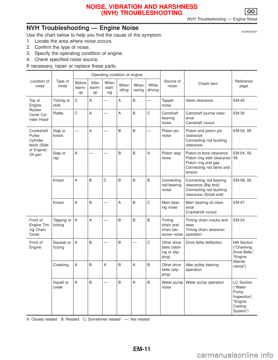
NVH Troubleshooting Ð Engine NoiseNCEM0005S01Use the chart below to help you find the cause of the symptom.
1. Locate the area where noise occurs.
2. Confirm the type of noise.
3. Specify the operating condition of engine.
4. Check specified noise source.
If necessary, repair or replace these parts.
Location of
noiseType of
noiseOperating condition of engine
Source of
noiseCheck itemReference
page Before
warm-
upAfter
warm-
upWhen
start-
ingWhen
idlingWhen
racingWhile
driving
To p o f
Engine
Rocker
Cover Cyl-
inder HeadTicking or
clickC A Ð A B Ð Tappet
noiseValve clearance EM-40
Rattle C A Ð A B C Camshaft
bearing
noiseCamshaft journal clear-
ance
Camshaft runoutEM-35
Crankshaft
Pulley
Cylinder
block (Side
of Engine)
Oil panSlap or
knockÐ A Ð B B Ð Piston pin
noisePiston and piston pin
clearance
Connecting rod bushing
clearanceEM-54, 59
Slap or
rapA Ð Ð B B A Piston slap
noisePiston-to-bore clearance
Piston ring side clearance
Piston ring end gap
Connecting rod bend and
torsionEM-54, 55,
56
Knock A B CB B B Connecting
rod-bearing
noiseConnecting rod bearing
clearance (Big end)
Connecting rod bushing
clearance (Small end)EM-58, 59
Knock A B Ð A B C Main bear-
ing noiseMain bearing oil clear-
ance
Crankshaft runoutEM-57
Front of
Engine Tim-
ing Chain
CoverTapping or
tickingAAÐBBBTiming
chain and
chain ten-
sioner noiseTiming chain cracks and
wear
Timing chain tensioner
operationEM-24
Front of
EngineSqueak or
fizzingA B Ð B Ð C Other drive
belts (stick-
ing or slip-
ping)Drive belts deflection MA Section
(ªChecking
Drive Beltsº,
ªEngine
Mainte-
nanceº) CreakingABABABOther drive
belts (slip-
ping)Idler pulley bearing
operation
Squall or
creakABÐBABWater pump
noiseWater pump operation LC Section
(ªWater
Pump
Inspectionº,
ªEngine
Cooling
Systemº)
A: Closely related B: Related C: Sometimes related Ð: Not related
NOISE, VIBRATION AND HARSHNESS
(NVH) TROUBLESHOOTINGQG
NVH Troubleshooting Ð Engine Noise
EM-11
Page 1552 of 2267
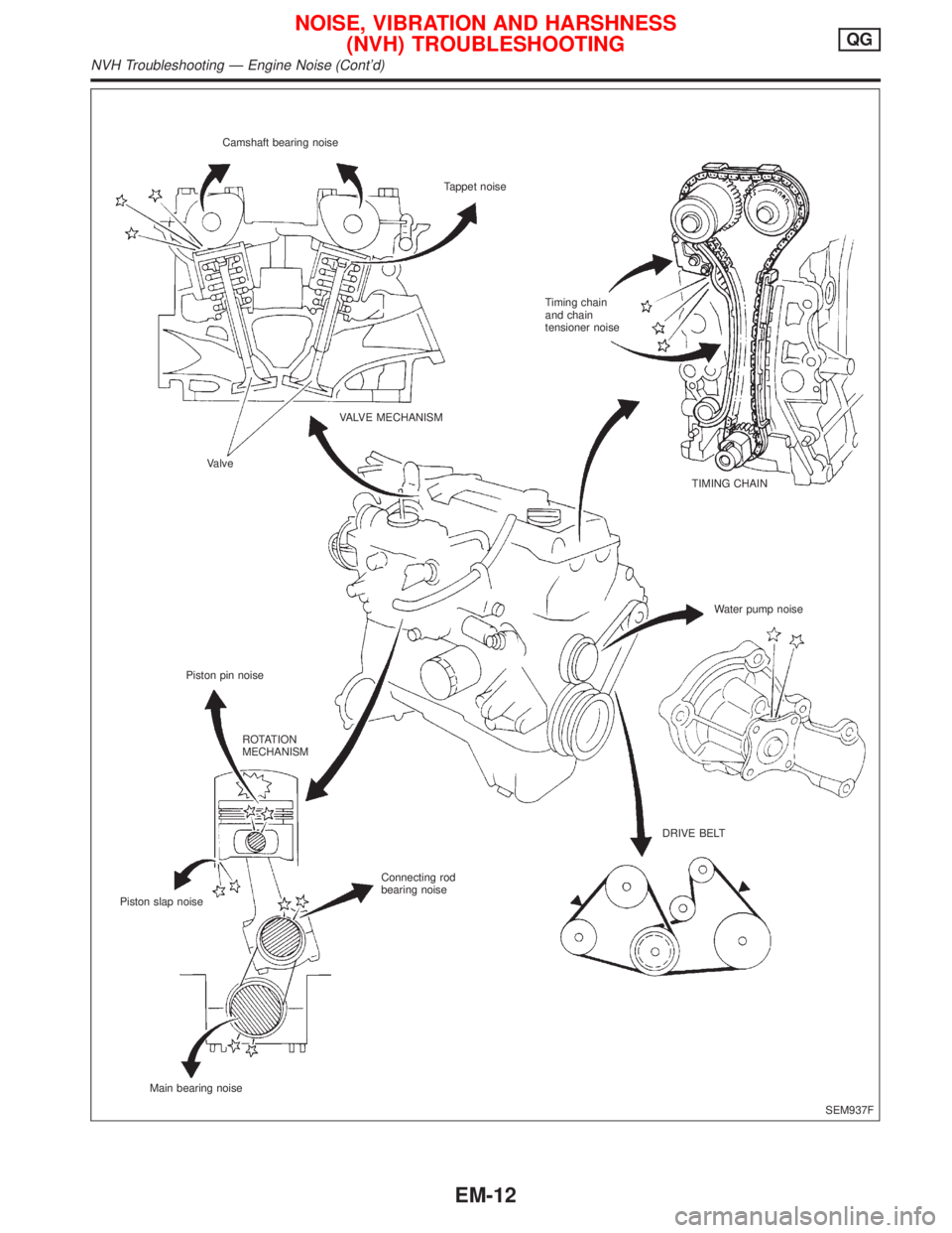
SEM937F Camshaft bearing noise
Tappet noise
Timing chain
and chain
tensioner noise
VALVE MECHANISM
Valve
Piston pin noiseTIMING CHAIN
Water pump noise
ROTATION
MECHANISM
DRIVE BELT
Connecting rod
bearing noise
Piston slap noise
Main bearing noise
NOISE, VIBRATION AND HARSHNESS
(NVH) TROUBLESHOOTINGQG
NVH Troubleshooting Ð Engine Noise (Cont'd)
EM-12