1999 NISSAN PRIMERA oil pressure
[x] Cancel search: oil pressurePage 4 of 2267
Wiring Diagram - AT - LPSV......................................76
Diagnostic Procedure ................................................77
Component Inspection ...............................................78
DTC P1705 THROTTLE POSITION SENSOR.............79
Description .................................................................79
Wiring Diagram - AT - TPS ........................................81
Diagnostic Procedure ................................................82
Component Inspection ...............................................85
DTC P1777 STEP MOTOR - CIRCUIT.........................86
Description .................................................................86
Wiring Diagram - AT - STM .......................................88
Diagnostic Procedure ................................................89
Component Inspection ...............................................90
DTC P1778 STEP MOTOR - FUNCTION.....................91
Description .................................................................91
Diagnostic Procedure ................................................93
DTC P1791 CVT FLUID PRESSURE SENSOR...........94
Description .................................................................94
Wiring Diagram - AT - FPS ........................................96
Diagnostic Procedure ................................................97
Component Inspection ...............................................98
CVT SAFE FUNCTION..................................................99
Description .................................................................99
Diagnostic Procedure ..............................................100
CONTROL UNIT (RAM), CONTROL UNIT (ROM).....101
Description ...............................................................101Diagnostic Procedure ..............................................102
CONTROL UNIT (EEPROM).......................................103
Description ...............................................................103
Diagnostic Procedure ..............................................104
TROUBLE DIAGNOSES FOR NON-DETECTABLE
ITEMS...........................................................................105
PNP Switch, Stop Lamp Switch and Throttle
Position Switch ........................................................105
Wiring Diagram - AT - NONDTC ............................. 110
ON-VEHICLE SERVICE.............................................. 114
Control Cable Adjustment ........................................ 114
Park/Neutral Position (PNP) Switch Adjustment ..... 114
Differential Side Oil Seal Replacement ................... 114
REMOVAL AND INSTALLATION............................... 116
Removal ................................................................... 116
Inspection................................................................. 116
Installation ................................................................ 117
Air Breather Hose .................................................... 118
CVT Fluid Cooler (Hyper CVT-M6) ......................... 118
Components............................................................. 119
SERVICE DATA AND SPECIFICATIONS (SDS).......120
General Specifications .............................................120
Stall Revolution ........................................................120
Line Pressure...........................................................120
Removal and Installation .........................................120
CONTENTS(Cont'd)
AT-2
Page 10 of 2267
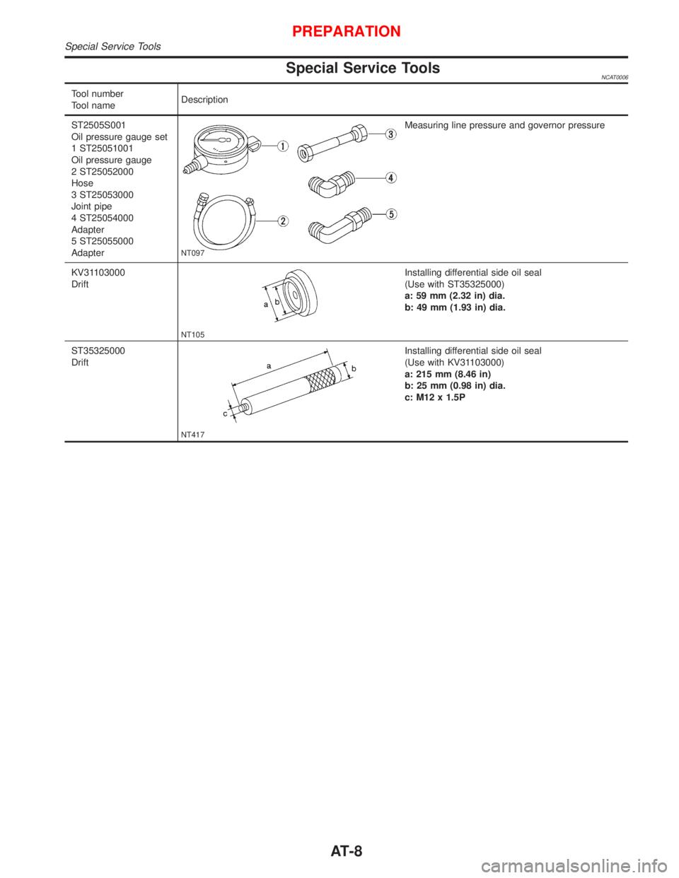
Special Service ToolsNCAT0006
Tool number
Tool nameDescription
ST2505S001
Oil pressure gauge set
1 ST25051001
Oil pressure gauge
2 ST25052000
Hose
3 ST25053000
Joint pipe
4 ST25054000
Adapter
5 ST25055000
Adapter
NT097
Measuring line pressure and governor pressure
KV31103000
Drift
NT105
Installing differential side oil seal
(Use with ST35325000)
a: 59 mm (2.32 in) dia.
b: 49 mm (1.93 in) dia.
ST35325000
Drift
NT417
Installing differential side oil seal
(Use with KV31103000)
a: 215 mm (8.46 in)
b: 25 mm (0.98 in) dia.
c: M12 x 1.5P
PREPARATION
Special Service Tools
AT-8
Page 15 of 2267
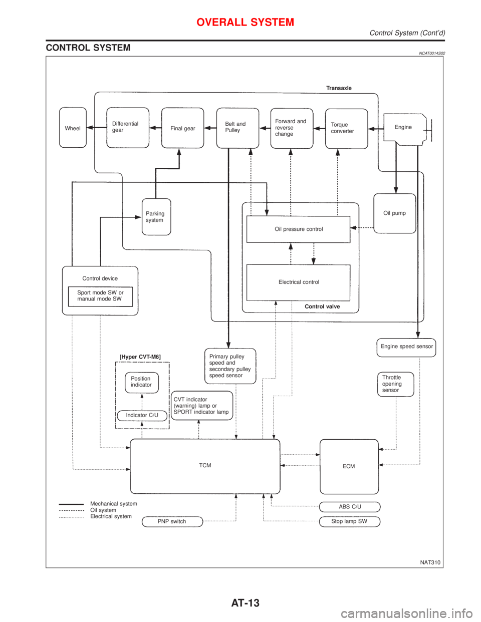
CONTROL SYSTEMNCAT0014S02
NAT310 WheelDifferential
gearFinal gearBelt and
PulleyForward and
reverse
changeTorque
converterEngine Transaxle
Oil pump
Oil pressure control Parking
system
Control device
Sport mode SW or
manual mode SWElectrical control
Control valve
Primary pulley
speed and
secondary pulley
speed sensor
CVT indicator
(warning) lamp or
SPORT indicator lamp [Hyper CVT-M6]
Position
indicator
Indicator C/U
TCM
Mechanical system
Oil system
Electrical system
Stop lamp SWABS C/UECMThrottle
opening
sensor Engine speed sensor
PNP switch
OVERALL SYSTEM
Control System (Cont'd)
AT-13
Page 25 of 2267
![NISSAN PRIMERA 1999 Electronic Repair Manual Item DisplayMonitor item
Description Remarks
TCM input
signalsMain
signals
Non-manual mode switch NON M MODE
SW [ON/OFF] X ÐION/OFF position signal
of non-manual mode
switch is displayed.Ð
Up switch NISSAN PRIMERA 1999 Electronic Repair Manual Item DisplayMonitor item
Description Remarks
TCM input
signalsMain
signals
Non-manual mode switch NON M MODE
SW [ON/OFF] X ÐION/OFF position signal
of non-manual mode
switch is displayed.Ð
Up switch](/manual-img/5/57377/w960_57377-24.png)
Item DisplayMonitor item
Description Remarks
TCM input
signalsMain
signals
Non-manual mode switch NON M MODE
SW [ON/OFF] X ÐION/OFF position signal
of non-manual mode
switch is displayed.Ð
Up switch UP SW
[ON/OFF] X ÐION/OFF position signal
of up switch is dis-
played.Ð
Down switch DOWN SW
[ON/OFF] X ÐION/OFF position signal
of down switch is dis-
played.Ð
Step motor coil A S/M COIL [A]
[ON/OFF]
ÐÐIControl valve of step
motor coil A, computed
by TCM from each input
signal is displayed.Ð
Step motor coil B S/M COIL [B]
[ON/OFF]
ÐÐIControl valve of step
motor coil B, computed
by TCM from each input
signal is displayed.Ð
Step motor coil C S/M COIL [C]
[ON/OFF]
ÐÐIControl valve of step
motor coil C, computed
by TCM from each input
signal is displayed.Ð
Step motor coil D S/M COIL [D]
[ON/OFF]
ÐÐIControl valve of step
motor coil D, computed
by TCM from each input
signal is displayed.Ð
CVT ratio CVT RATIO [Ð]
ÐXIReal CVT ratio operated
TCM is displayed.Ð
Step PLY CONT
STEP [step]ÐXIStep motor position is
displayed.Ð
Line pressure LINE PRES-
SURE [MPa]
ÐXIReal line pressure cal-
culated from line pres-
sure sensor voltage
with TCM is displayed.Ð
Pulley rpm×in 2 T RPM [rpm]
ÐÐITarget primary pulley
speed operated with
TCM is displayed.Ð
CVT ratio 2 T RATIO [Ð]
ÐÐITarget changing the
speed ratio operated
with TCM is displayed.Ð
Step 2 T STEP [step]
ÐÐITarget step motor posi-
tion operated with TCM
is displayed.Ð
X: Applicable
Ð: Not applicable
ON BOARD DIAGNOSTIC SYSTEM DESCRIPTION
CONSULT-II (Cont'd)
AT-23
Page 37 of 2267
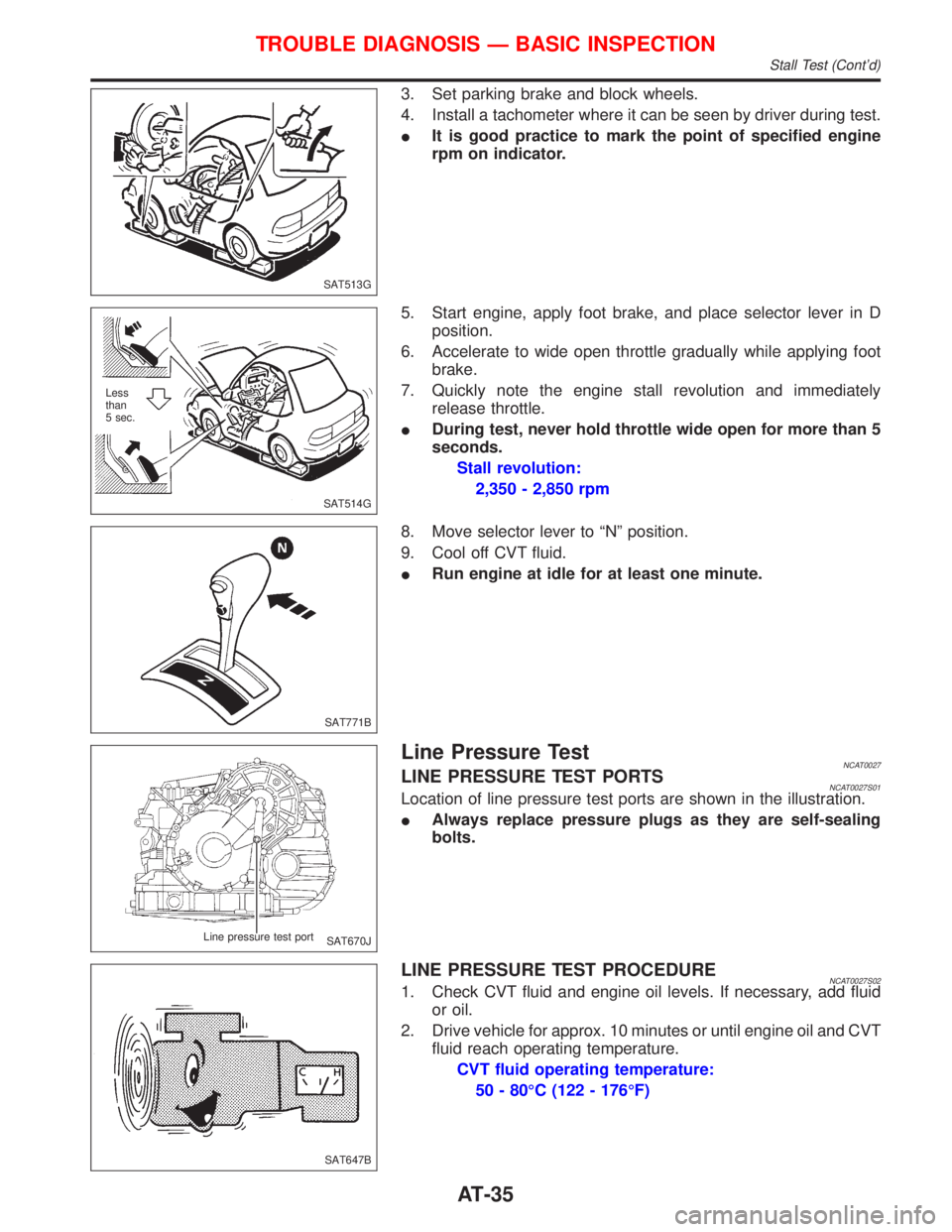
3. Set parking brake and block wheels.
4. Install a tachometer where it can be seen by driver during test.
IIt is good practice to mark the point of specified engine
rpm on indicator.
5. Start engine, apply foot brake, and place selector lever in D
position.
6. Accelerate to wide open throttle gradually while applying foot
brake.
7. Quickly note the engine stall revolution and immediately
release throttle.
IDuring test, never hold throttle wide open for more than 5
seconds.
Stall revolution:
2,350 - 2,850 rpm
8. Move selector lever to ªNº position.
9. Cool off CVT fluid.
IRun engine at idle for at least one minute.
Line Pressure TestNCAT0027LINE PRESSURE TEST PORTSNCAT0027S01Location of line pressure test ports are shown in the illustration.
IAlways replace pressure plugs as they are self-sealing
bolts.
LINE PRESSURE TEST PROCEDURENCAT0027S021. Check CVT fluid and engine oil levels. If necessary, add fluid
or oil.
2. Drive vehicle for approx. 10 minutes or until engine oil and CVT
fluid reach operating temperature.
CVT fluid operating temperature:
50 - 80ÉC (122 - 176ÉF)
SAT513G
SAT514G Less
than
5 sec.
SAT771B
SAT670J Line pressure test port
SAT647B
TROUBLE DIAGNOSIS Ð BASIC INSPECTION
Stall Test (Cont'd)
AT-35
Page 76 of 2267
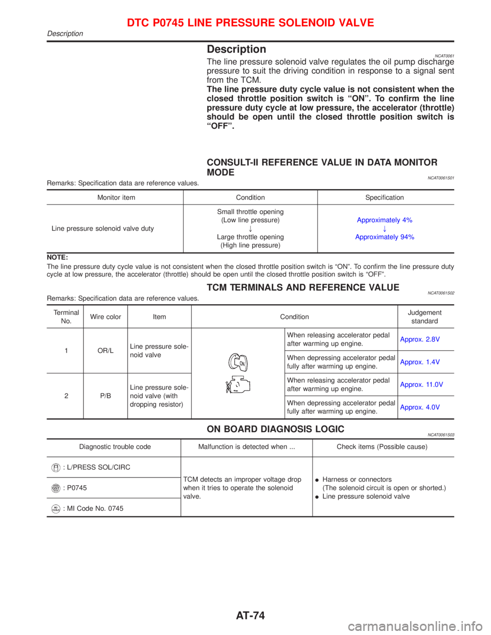
DescriptionNCAT0061The line pressure solenoid valve regulates the oil pump discharge
pressure to suit the driving condition in response to a signal sent
from the TCM.
The line pressure duty cycle value is not consistent when the
closed throttle position switch is ªONº. To confirm the line
pressure duty cycle at low pressure, the accelerator (throttle)
should be open until the closed throttle position switch is
ªOFFº.
CONSULT-II REFERENCE VALUE IN DATA MONITOR
MODE
NCAT0061S01Remarks: Specification data are reference values.
Monitor item Condition Specification
Line pressure solenoid valve dutySmall throttle opening
(Low line pressure)
"
Large throttle opening
(High line pressure)Approximately 4%
"
Approximately 94%
NOTE:
The line pressure duty cycle value is not consistent when the closed throttle position switch is ªONº. To confirm the line pressure duty
cycle at low pressure, the accelerator (throttle) should be open until the closed throttle position switch is ªOFFº.
TCM TERMINALS AND REFERENCE VALUENCAT0061S02Remarks: Specification data are reference values.
Terminal
No.Wire color Item ConditionJudgement
standard
1 OR/LLine pressure sole-
noid valve
When releasing accelerator pedal
after warming up engine.Approx. 2.8V
When depressing accelerator pedal
fully after warming up engine.Approx. 1.4V
2 P/BLine pressure sole-
noid valve (with
dropping resistor)When releasing accelerator pedal
after warming up engine.Approx. 11.0V
When depressing accelerator pedal
fully after warming up engine.Approx. 4.0V
ON BOARD DIAGNOSIS LOGICNCAT0061S03
Diagnostic trouble code Malfunction is detected when ... Check items (Possible cause)
: L/PRESS SOL/CIRC
TCM detects an improper voltage drop
when it tries to operate the solenoid
valve.IHarness or connectors
(The solenoid circuit is open or shorted.)
ILine pressure solenoid valve
: P0745
: MI Code No. 0745
DTC P0745 LINE PRESSURE SOLENOID VALVE
Description
AT-74
Page 221 of 2267
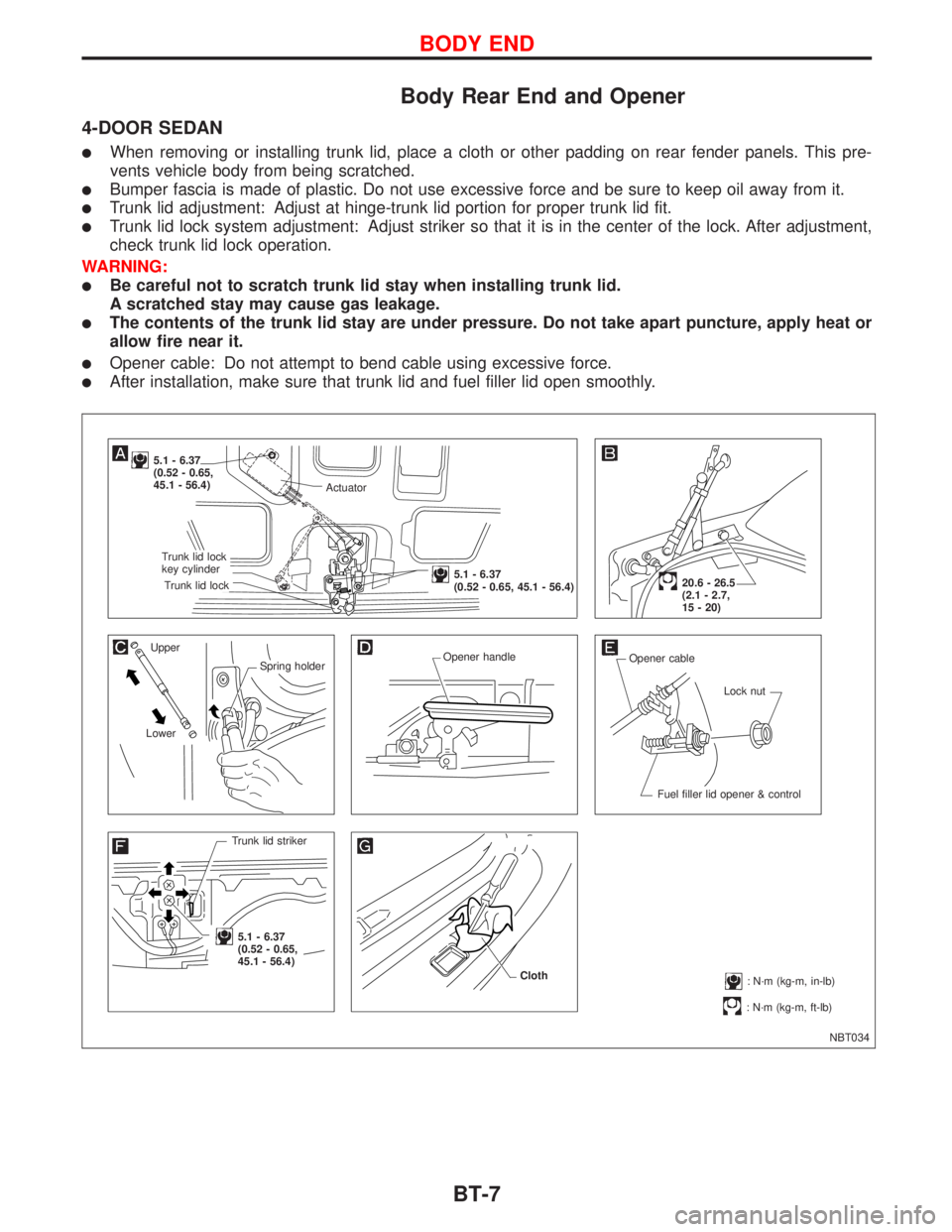
Body Rear End and Opener
4-DOOR SEDAN
lWhen removing or installing trunk lid, place a cloth or other padding on rear fender panels. This pre-
vents vehicle body from being scratched.
lBumper fascia is made of plastic. Do not use excessive force and be sure to keep oil away from it.
lTrunk lid adjustment: Adjust at hinge-trunk lid portion for proper trunk lid fit.
lTrunk lid lock system adjustment: Adjust striker so that it is in the center of the lock. After adjustment,
check trunk lid lock operation.
WARNING:
lBe careful not to scratch trunk lid stay when installing trunk lid.
A scratched stay may cause gas leakage.
lThe contents of the trunk lid stay are under pressure. Do not take apart puncture, apply heat or
allow fire near it.
lOpener cable: Do not attempt to bend cable using excessive force.
lAfter installation, make sure that trunk lid and fuel filler lid open smoothly.
NBT034
5.1 - 6.37
(0.52 - 0.65,
45.1 - 56.4)
Upper
Spring holder
LowerOpener handle
Opener cable
Lock nut
Fuel filler lid opener & control
Trunk lid striker
.5.1 - 6.37
(0.52 - 0.65,
45.1 - 56.4)
: N´m (kg-m, ft-lb)
20.6 - 26.5
(2.1 - 2.7,
15 - 20)
: N´m (kg-m, in-lb) Cloth
Actuator
.Trunk lid lock
key cylinder
.Trunk lid lock
.5.1 - 6.37
(0.52 - 0.65, 45.1 - 56.4)
BODY END
BT-7
Page 289 of 2267
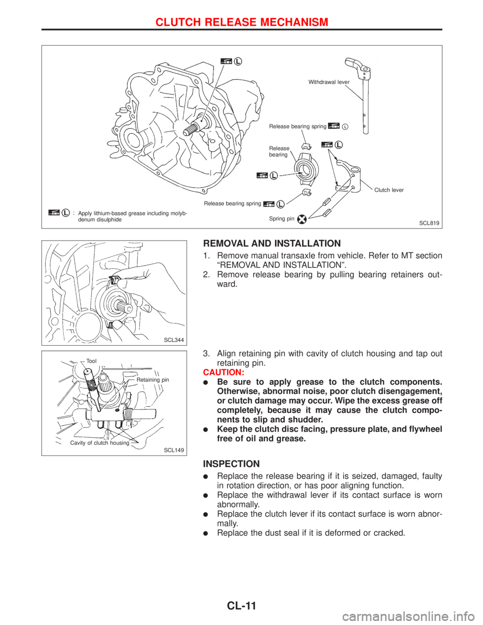
REMOVAL AND INSTALLATION
1. Remove manual transaxle from vehicle. Refer to MT section
ªREMOVAL AND INSTALLATIONº.
2. Remove release bearing by pulling bearing retainers out-
ward.
3. Align retaining pin with cavity of clutch housing and tap out
retaining pin.
CAUTION:
lBe sure to apply grease to the clutch components.
Otherwise, abnormal noise, poor clutch disengagement,
or clutch damage may occur. Wipe the excess grease off
completely, because it may cause the clutch compo-
nents to slip and shudder.
lKeep the clutch disc facing, pressure plate, and flywheel
free of oil and grease.
INSPECTION
lReplace the release bearing if it is seized, damaged, faulty
in rotation direction, or has poor aligning function.
lReplace the withdrawal lever if its contact surface is worn
abnormally.
lReplace the clutch lever if its contact surface is worn abnor-
mally.
lReplace the dust seal if it is deformed or cracked.
SCL819 Withdrawal lever
Release bearing spring
pL
Release
bearing
Release bearing spring
Spring pinClutch lever
Apply lithium-based grease including molyb-
denum disulphide
SCL344
SCL149 Tool
Retaining pin
Cavity of clutch housing
CLUTCH RELEASE MECHANISM
CL-11