Page 118 of 2267
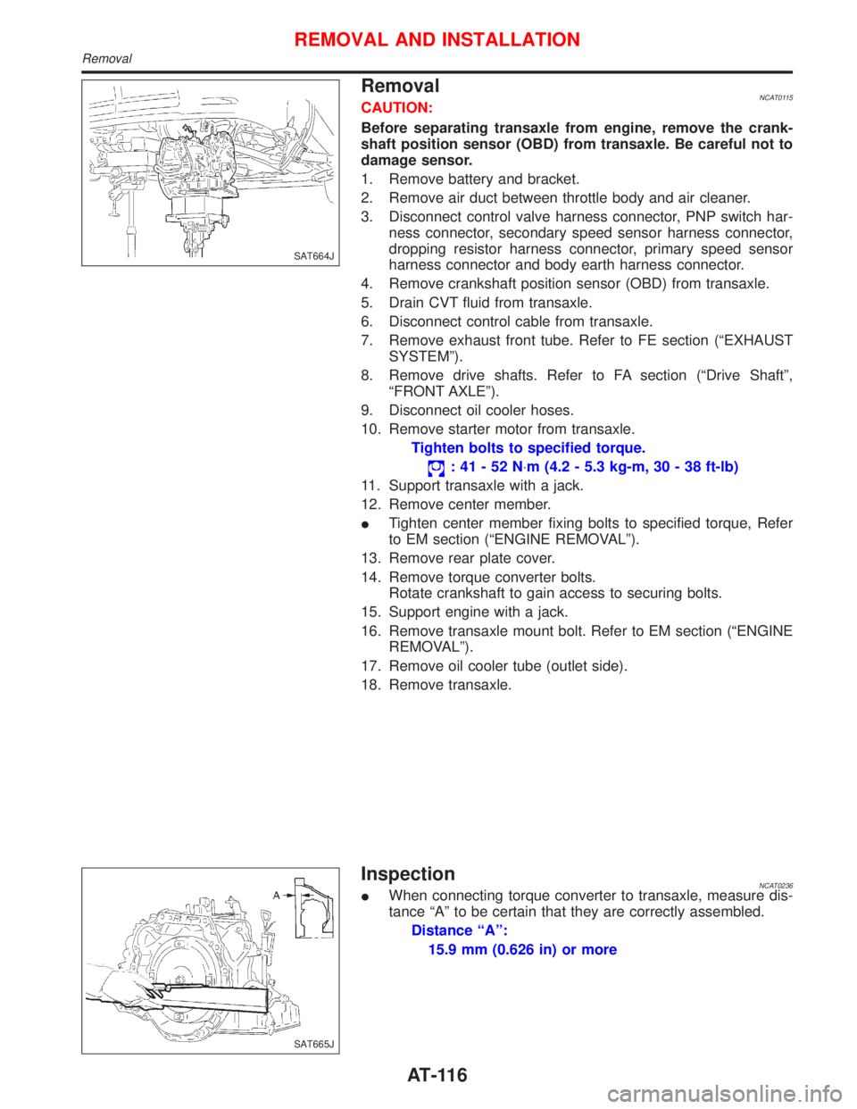
RemovalNCAT0115CAUTION:
Before separating transaxle from engine, remove the crank-
shaft position sensor (OBD) from transaxle. Be careful not to
damage sensor.
1. Remove battery and bracket.
2. Remove air duct between throttle body and air cleaner.
3. Disconnect control valve harness connector, PNP switch har-
ness connector, secondary speed sensor harness connector,
dropping resistor harness connector, primary speed sensor
harness connector and body earth harness connector.
4. Remove crankshaft position sensor (OBD) from transaxle.
5. Drain CVT fluid from transaxle.
6. Disconnect control cable from transaxle.
7. Remove exhaust front tube. Refer to FE section (ªEXHAUST
SYSTEMº).
8. Remove drive shafts. Refer to FA section (ªDrive Shaftº,
ªFRONT AXLEº).
9. Disconnect oil cooler hoses.
10. Remove starter motor from transaxle.
Tighten bolts to specified torque.
:41-52N×m (4.2 - 5.3 kg-m, 30 - 38 ft-lb)
11. Support transaxle with a jack.
12. Remove center member.
ITighten center member fixing bolts to specified torque, Refer
to EM section (ªENGINE REMOVALº).
13. Remove rear plate cover.
14. Remove torque converter bolts.
Rotate crankshaft to gain access to securing bolts.
15. Support engine with a jack.
16. Remove transaxle mount bolt. Refer to EM section (ªENGINE
REMOVALº).
17. Remove oil cooler tube (outlet side).
18. Remove transaxle.
InspectionNCAT0236IWhen connecting torque converter to transaxle, measure dis-
tance ªAº to be certain that they are correctly assembled.
Distance ªAº:
15.9 mm (0.626 in) or more
SAT664J
SAT665J
REMOVAL AND INSTALLATION
Removal
AT-116
Page 121 of 2267
Components
NAT311 Fluid level gauge
Fluid charging pipe
5.0 - 6.8 (0.5 - 0.7, 44 - 60)
PNP SW5.0 - 6.8
(0.5 - 0.7, 44 - 60)
Dropping resistor
Secondary pulley speed sensor
5.0 - 6.8
(0.5 - 0.7, 44 - 60)
Speedometer pinion
O-ring
O-ringDifferential
oil seal
Torque converter
Input shaft O-ring
Oil pump
oil seal
CVT assy
Oil pan installation bolt (18)
6.9 - 8.8 (0.7 - 0.9, 61 - 78)
: N´m (kg-m, in-lb)
: N´m (kg-m, ft-lb)
: CVT fluid NS-1Oil panMagnetDrain bolt
30 - 39 (3.0 - 4.0, 22 - 29)
Gasket
Oil pan gasket
4.5 - 5.7 (0.45 - 0.59, 40 - 50)Tube (inlet)
40-58
(4.0 - 6.0,
30 - 43)
Copper washer
4.5 - 5.7
(0.45 - 0.59, 40 - 50) Tube (outlet)
4.5 - 5.7 (0.45 - 0.59, 40 - 50)Copper washer40 - 58 (4.0 - 6.0, 30 - 43)Primary pulley
speed sensor
5.0 - 6.8 (0.5 - 0.7, 44 - 60)
O-ring
O-ring
4.5 - 5.7 (0.45 - 0.59, 40 - 50)
Differential
oil seal
SEC. 310×311×312×319
REMOVAL AND INSTALLATION
Components
AT-119
Page 132 of 2267
Removal
CAUTION:
lBe careful not to splash brake fluid on painted areas; it
may cause paint damage. If brake fluid is splashed on
painted areas, wash it away with water immediately.
lAll hoses and tubes must be free from excessive
bending, twisting and pulling.
lFor rear disc caliper, care should be taken as not to let
air enter the body.
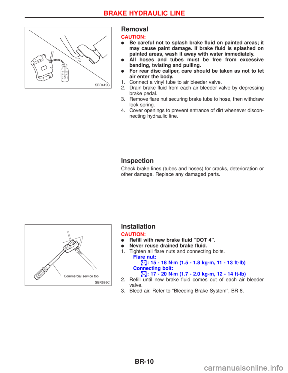
1. Connect a vinyl tube to air bleeder valve.
2. Drain brake fluid from each air bleeder valve by depressing
brake pedal.
3. Remove flare nut securing brake tube to hose, then withdraw
lock spring.
4. Cover openings to prevent entrance of dirt whenever discon-
necting hydraulic line.
Inspection
Check brake lines (tubes and hoses) for cracks, deterioration or
other damage. Replace any damaged parts.
Installation
CAUTION:
lRefill with new brake fluid ªDOT 4º.
lNever reuse drained brake fluid.
1. Tighten all flare nuts and connecting bolts.
Flare nut:
: 15 - 18 N´m (1.5 - 1.8 kg-m, 11 - 13 ft-lb)
Connecting bolt:
: 17 - 20 N´m (1.7 - 2.0 kg-m, 12 - 14 ft-lb)
2. Refill until new brake fluid comes out of each air bleeder
valve.
3. Bleed air. Refer to ªBleeding Brake Systemº, BR-8.
SBR419C
SBR686C Commercial service tool
BRAKE HYDRAULIC LINE
BR-10
Page 133 of 2267
Dual Proportioning Valve
INSPECTION
CAUTION:
lCarefully monitor brake fluid level at master cylinder.
lUse new brake fluid ªDOT 4º.
lBe careful not to splash brake fluid on painted areas; it
may cause paint damage. If brake fluid is splashed on
paint areas, wash it away with water immediately.
lDepress pedal slowly when raising front brake pressure.
lCheck rear brake pressure at least 2 seconds after front
brake pressure reaches specified value.
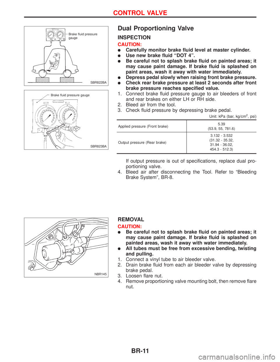
1. Connect brake fluid pressure gauge to air bleeders of front
and rear brakes on either LH or RH side.
2. Bleed air from the tool.
3. Check fluid pressure by depressing brake pedal.
Unit: kPa (bar, kg/cm2, psi)
Applied pressure (Front brake)5.39
(53.9, 55, 781.6)
Output pressure (Rear brake)3.132 - 3.532
(31.32 - 35.32,
31.94 - 36.02,
454.3 - 512.3)
If output pressure is out of specifications, replace dual pro-
portioning valve.
4. Bleed air after disconnecting the Tool. Refer to ªBleeding
Brake Systemº, BR-8.
REMOVAL
CAUTION:
lBe careful not to splash brake fluid on painted areas; it
may cause paint damage. If brake fluid is splashed on
painted areas, wash it away with water immediately.
lAll tubes must be free from excessive bending, twisting
and pulling.
1. Connect a vinyl tube to air bleeder valve.
2. Drain brake fluid from each air bleeder valve by depressing
brake pedal.
3. Loosen flare nut.
4. Remove proportioning valve mounting bolt, then remove flare
nut.
SBR822BA Brake fluid pressure
gauge
SBR823BA Brake fluid pressure gauge
NBR145
CONTROL VALVE
BR-11
Page 134 of 2267
INSTALLATION
CAUTION:
lRefill with new brake fluid ªDOT 4º.
lNever reuse drained brake fluid.
1. Temporarily fit flare nut to proportioning valve.
2. Tighten proportioning valve mounting bolt, then tighten flare
nut with wooden block placed between proportioning valve
and dash panel.
Flare nut:
: 15 - 18 N´m (1.5 - 1.8 kg-m, 11 - 13 ft-lb)
Mounting bolt:
: 5.1 - 8.8 N´m (0.52 - 0.9 kg-m, 45 - 78 in-lb)
3. Refill until new brake fluid comes out of each air bleeder
valve.
4. Bleed air. Refer to ªBleeding Brake Systemº, BR-8.
CONTROL VALVE
Dual Proportioning Valve (Cont'd)
BR-12
Page 141 of 2267
Inspection
OUTPUT ROD LENGTH CHECK
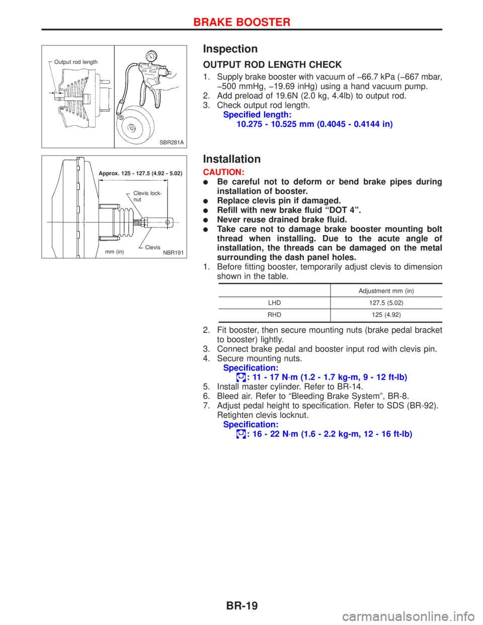
1. Supply brake booster with vacuum of þ66.7 kPa (þ667 mbar,
þ500 mmHg, þ19.69 inHg) using a hand vacuum pump.
2. Add preload of 19.6N (2.0 kg, 4.4lb) to output rod.
3. Check output rod length.
Specified length:
10.275 - 10.525 mm (0.4045 - 0.4144 in)
Installation
CAUTION:
lBe careful not to deform or bend brake pipes during
installation of booster.
lReplace clevis pin if damaged.
lRefill with new brake fluid ªDOT 4º.
lNever reuse drained brake fluid.
lTake care not to damage brake booster mounting bolt
thread when installing. Due to the acute angle of
installation, the threads can be damaged on the metal
surrounding the dash panel holes.
1. Before fitting booster, temporarily adjust clevis to dimension
shown in the table.
Adjustment mm (in)
LHD 127.5 (5.02)
RHD 125 (4.92)
2. Fit booster, then secure mounting nuts (brake pedal bracket
to booster) lightly.
3. Connect brake pedal and booster input rod with clevis pin.
4. Secure mounting nuts.
Specification:
: 11 - 17 N´m (1.2 - 1.7 kg-m,9-12ft-lb)
5. Install master cylinder. Refer to BR-14.
6. Bleed air. Refer to ªBleeding Brake Systemº, BR-8.
7. Adjust pedal height to specification. Refer to SDS (BR-92).
Retighten clevis locknut.
Specification:
: 16 - 22 N´m (1.6 - 2.2 kg-m, 12 - 16 ft-lb)
SBR281A Output rod length
Approx. 125 - 127.5 (4.92 - 5.02)
Clevis Clevis lock-
nut
mm (in)
NBR191
BRAKE BOOSTER
BR-19
Page 154 of 2267
Installation
CAUTION:
lRefill with new brake fluid ªDOT 4º.
lNever reuse drained brake fluid.
1. Install brake hose to caliper securely.
2. Install all parts and secure all bolts.
3. Bleed air. Refer to ªBleeding Brake Systemº BR-8.
NBR160
.Protrusions
NBR298 Protrusions
FRONT DISC BRAKE
BR-32
Page 161 of 2267
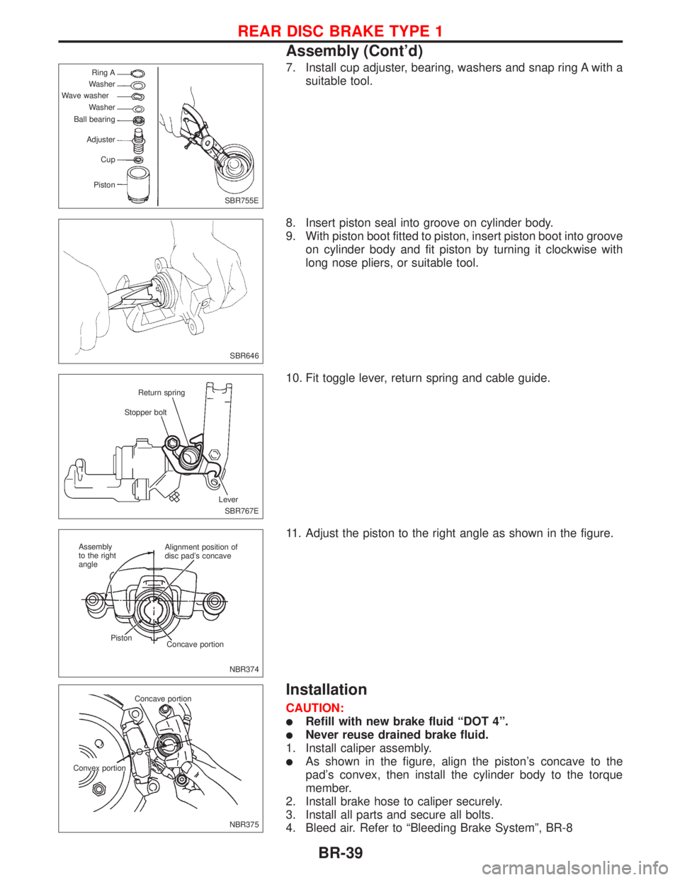
7. Install cup adjuster, bearing, washers and snap ring A with a
suitable tool.
8. Insert piston seal into groove on cylinder body.
9. With piston boot fitted to piston, insert piston boot into groove
on cylinder body and fit piston by turning it clockwise with
long nose pliers, or suitable tool.
10. Fit toggle lever, return spring and cable guide.
11. Adjust the piston to the right angle as shown in the figure.
Installation
CAUTION:
lRefill with new brake fluid ªDOT 4º.
lNever reuse drained brake fluid.
1. Install caliper assembly.
lAs shown in the figure, align the piston's concave to the
pad's convex, then install the cylinder body to the torque
member.
2. Install brake hose to caliper securely.
3. Install all parts and secure all bolts.
4. Bleed air. Refer to ªBleeding Brake Systemº, BR-8
SBR755E Ring A
Washer
Wave washer
Washer
Ball bearing
Adjuster
Cup
Piston
SBR646
SBR767E Stopper boltReturn spring
Lever
NBR374 Alignment position of
disc pad's concave
Concave portion Piston Assembly
to the right
angle
NBR375 Concave portion
Convex portion
REAR DISC BRAKE TYPE 1
Assembly (Cont'd)
BR-39