1999 NISSAN PRIMERA torque
[x] Cancel search: torquePage 3 of 2267
AUTOMATIC TRANSAXLE
SECTION
AT(H×CVT)
CONTENTS
TROUBLE DIAGNOSIS - INDEX....................................3
Alphabetical & P No. Index for DTC ...........................3
PRECAUTIONS...............................................................5
Precautions for Supplemental Restraint System
(SRS)²AIR BAG²and²SEAT BELT
PRE-TENSIONER²......................................................5
Precautions for On Board Diagnostic (OBD)
System of CVT and Engine .........................................5
Precautions ..................................................................5
Service Notice or Precautions .....................................6
Wiring Diagrams and Trouble Diagnosis .....................7
PREPARATION...............................................................8
Special Service Tools ..................................................8
OVERALL SYSTEM........................................................9
CVT Electrical Parts Location......................................9
Circuit Diagram ..........................................................10
Cross-sectional View - RE0F06A .............................. 11
Control System ..........................................................12
ON BOARD DIAGNOSTIC SYSTEM
DESCRIPTION...............................................................15
Introduction ................................................................15
OBD Function for CVT System .................................15
OBD Diagnostic Trouble Code (DTC) .......................15
Malfunction Indicator (MI) ..........................................18
CONSULT-II ...............................................................18
TROUBLE DIAGNOSIS - INTRODUCTION..................29
Introduction ................................................................29
Work Flow ..................................................................32
TROUBLE DIAGNOSIS - BASIC INSPECTION...........34
CVT Fluid Check .......................................................34
Stall Test ....................................................................34
Line Pressure Test .....................................................35
Road Test...................................................................36
TROUBLE DIAGNOSIS - GENERAL
DESCRIPTION...............................................................41
TCM Terminals and Reference Value........................41TROUBLE DIAGNOSIS FOR POWER SUPPLY..........45
Wiring Diagram - CVT - MAIN...................................45
DTC P0705 PARK/NEUTRAL POSITION (PNP)
SWITCH.........................................................................48
Description .................................................................48
Wiring Diagram - AT - PNP/SW.................................50
Diagnostic Procedure ................................................51
Component Inspection ...............................................53
DTC P0710 CVT FLUID TEMPERATURE SENSOR
CIRCUIT.........................................................................54
Description .................................................................54
Wiring Diagram - AT - FTS ........................................56
Diagnostic Procedure ................................................57
DTC P0715 PRIMARY SPEED SENSOR.....................59
Description .................................................................59
Wiring Diagram - AT - VSSA/T ..................................60
Diagnostic Procedure ................................................61
Component Inspection ...............................................61
DTC P0720 VEHICLE SPEED SENSOR CVT
(SECONDARY SPEED SENSOR)................................62
Description .................................................................62
Wiring Diagram - AT - VSSA/T ..................................64
Diagnostic Procedure ................................................65
Component Inspection ...............................................65
DTC P0725 ENGINE SPEED SIGNAL.........................66
Description .................................................................66
Wiring Diagram - AT - ENGSS ..................................67
Diagnostic Procedure ................................................68
DTC P0740 TORQUE CONVERTER CLUTCH
SOLENOID VALVE........................................................69
Description .................................................................69
Wiring Diagram - AT - TCV........................................71
Diagnostic Procedure ................................................72
Component Inspection ...............................................73
DTC P0745 LINE PRESSURE SOLENOID VALVE.....74
Description .................................................................74
AT
Page 8 of 2267
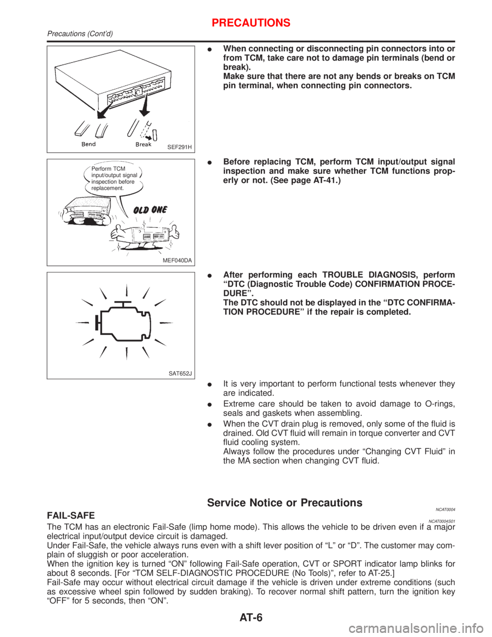
IWhen connecting or disconnecting pin connectors into or
from TCM, take care not to damage pin terminals (bend or
break).
Make sure that there are not any bends or breaks on TCM
pin terminal, when connecting pin connectors.
IBefore replacing TCM, perform TCM input/output signal
inspection and make sure whether TCM functions prop-
erly or not. (See page AT-41.)
IAfter performing each TROUBLE DIAGNOSIS, perform
ªDTC (Diagnostic Trouble Code) CONFIRMATION PROCE-
DUREº.
The DTC should not be displayed in the ªDTC CONFIRMA-
TION PROCEDUREº if the repair is completed.
IIt is very important to perform functional tests whenever they
are indicated.
IExtreme care should be taken to avoid damage to O-rings,
seals and gaskets when assembling.
IWhen the CVT drain plug is removed, only some of the fluid is
drained. Old CVT fluid will remain in torque converter and CVT
fluid cooling system.
Always follow the procedures under ªChanging CVT Fluidº in
the MA section when changing CVT fluid.
Service Notice or PrecautionsNCAT0004FAIL-SAFENCAT0004S01The TCM has an electronic Fail-Safe (limp home mode). This allows the vehicle to be driven even if a major
electrical input/output device circuit is damaged.
Under Fail-Safe, the vehicle always runs even with a shift lever position of ªLº or ªDº. The customer may com-
plain of sluggish or poor acceleration.
When the ignition key is turned ªONº following Fail-Safe operation, CVT or SPORT indicator lamp blinks for
about 8 seconds. [For ªTCM SELF-DIAGNOSTIC PROCEDURE (No Tools)º, refer to AT-25.]
Fail-Safe may occur without electrical circuit damage if the vehicle is driven under extreme conditions (such
as excessive wheel spin followed by sudden braking). To recover normal shift pattern, turn the ignition key
ªOFFº for 5 seconds, then ªONº.
SEF291H
MEF040DA Perform TCM
input/output signal
inspection before
replacement.
SAT652J
PRECAUTIONS
Precautions (Cont'd)
AT-6
Page 13 of 2267
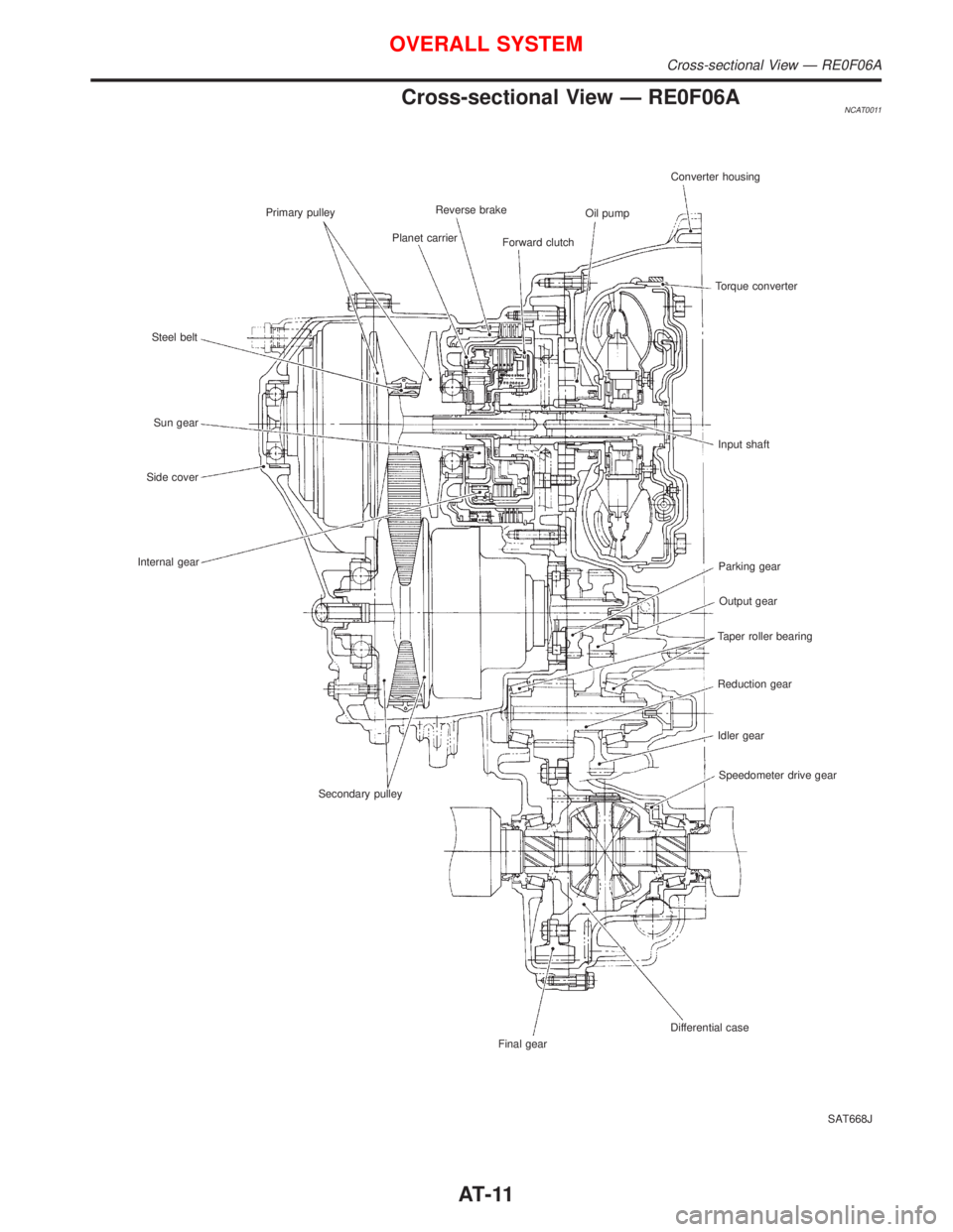
Cross-sectional View Ð RE0F06ANCAT0011
SAT668J Primary pulley
Steel belt
Sun gear
Side cover
Internal gear
Secondary pulley
Final gearDifferential caseSpeedometer drive gear Idler gear Reduction gear Taper roller bearingOutput gear Parking gear Input shaft Torque converter Converter housing
Oil pump
Forward clutch Reverse brake
Planet carrier
OVERALL SYSTEM
Cross-sectional View Ð RE0F06A
AT-11
Page 14 of 2267
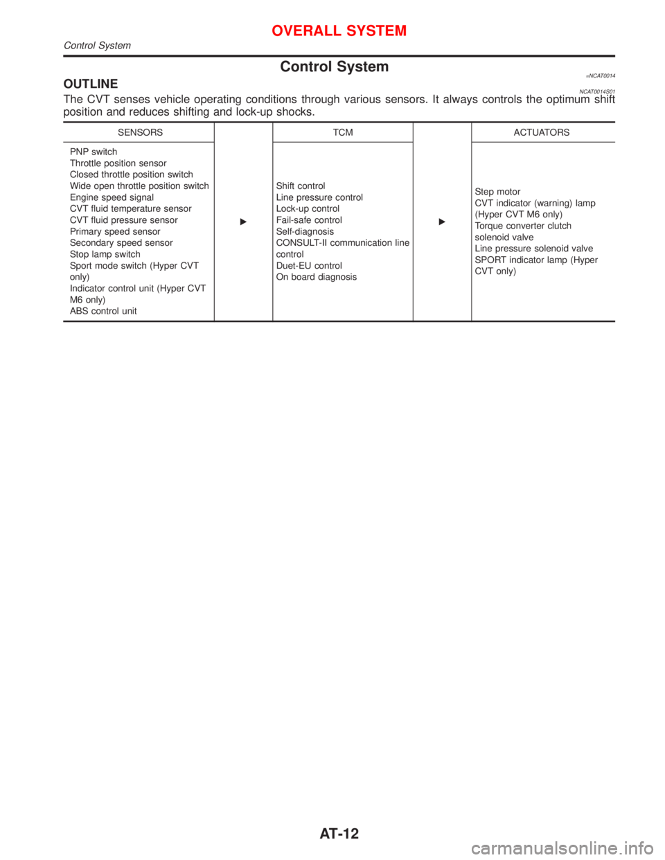
Control System=NCAT0014OUTLINENCAT0014S01The CVT senses vehicle operating conditions through various sensors. It always controls the optimum shift
position and reduces shifting and lock-up shocks.
SENSORS
ETCM
EACTUATORS
PNP switch
Throttle position sensor
Closed throttle position switch
Wide open throttle position switch
Engine speed signal
CVT fluid temperature sensor
CVT fluid pressure sensor
Primary speed sensor
Secondary speed sensor
Stop lamp switch
Sport mode switch (Hyper CVT
only)
Indicator control unit (Hyper CVT
M6 only)
ABS control unitShift control
Line pressure control
Lock-up control
Fail-safe control
Self-diagnosis
CONSULT-II communication line
control
Duet-EU control
On board diagnosisStep motor
CVT indicator (warning) lamp
(Hyper CVT M6 only)
Torque converter clutch
solenoid valve
Line pressure solenoid valve
SPORT indicator lamp (Hyper
CVT only)
OVERALL SYSTEM
Control System
AT-12
Page 15 of 2267
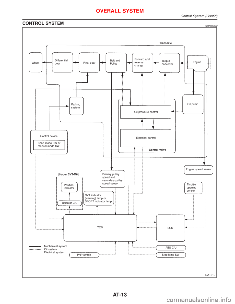
CONTROL SYSTEMNCAT0014S02
NAT310 WheelDifferential
gearFinal gearBelt and
PulleyForward and
reverse
changeTorque
converterEngine Transaxle
Oil pump
Oil pressure control Parking
system
Control device
Sport mode SW or
manual mode SWElectrical control
Control valve
Primary pulley
speed and
secondary pulley
speed sensor
CVT indicator
(warning) lamp or
SPORT indicator lamp [Hyper CVT-M6]
Position
indicator
Indicator C/U
TCM
Mechanical system
Oil system
Electrical system
Stop lamp SWABS C/UECMThrottle
opening
sensor Engine speed sensor
PNP switch
OVERALL SYSTEM
Control System (Cont'd)
AT-13
Page 16 of 2267
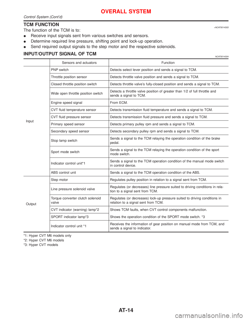
TCM FUNCTION=NCAT0014S03The function of the TCM is to:
IReceive input signals sent from various switches and sensors.
IDetermine required line pressure, shifting point and lock-up operation.
ISend required output signals to the step motor and the respective solenoids.
INPUT/OUTPUT SIGNAL OF TCMNCAT0014S04
Sensors and actuators Function
InputPNP switch Detects select lever position and sends a signal to TCM.
Throttle position sensor Detects throttle valve position and sends a signal to TCM.
Closed throttle position switch Detects throttle valve's fully-closed position and sends a signal to TCM.
Wide open throttle position switchDetects a throttle valve position of greater than 1/2 of full throttle and
sends a signal to TCM.
Engine speed signal From ECM.
CVT fluid temperature sensor Detects transmission fluid temperature and sends a signal to TCM.
CVT fluid pressure sensor Detects transmission fluid pressure and sends a signal to TCM.
Primary speed sensor Detects primary pulley rpm and sends a signal to TCM.
Secondary speed sensor Detects secondary pulley rpm and sends a signal to TCM.
Stop lamp switchSends a signal to the TCM relaying the operation condition of the brake
pedal.
Sport mode switchSends a signal to the TCM relaying the operation condition of the sport
mode switch.
Indicator control unit*1Sends a signal to the TCM operation condition of the manual mode switch
in control device.
ABS control unit Sends a signal to the TCM operation condition of the ABS.
OutputStep motor Regulates pulley position in relation to a signal sent from TCM.
Line pressure solenoid valveRegulates (or decreases) line pressure suited to driving conditions in rela-
tion to a signal sent from TCM.
Torque converter clutch solenoid
valveRegulates (or decreases) lock-up pressure suited to driving conditions in
relation to a signal sent from TCM.
CVT indicator (warning) lamp*2 Shows TCM faults, when CVT control components malfunction.
SPORT indicator lamp*3 Shows the operation condition of the SPORT mode switch. *3
Indicator control unit *1Receives the information of gear position on manual mode from TCM, and
sends a signal to indicator.
*1: Hyper CVT M6 models only
*2: Hyper CVT M6 models
*3: Hyper CVT models
OVERALL SYSTEM
Control System (Cont'd)
AT-14
Page 24 of 2267
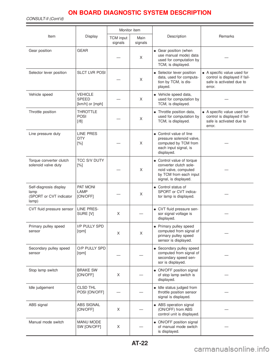
Item DisplayMonitor item
Description Remarks
TCM input
signalsMain
signals
Gear position GEAR
ÐXIGear position (when
use manual mode) data
used for computation by
TCM, is displayed.Ð
Selector lever position SLCT LVR POSI
ÐXISelector lever position
data, used for computa-
tion by TCM, is dis-
played.IA specific value used for
control is displayed if fail-
safe is activated due to
error.
Vehicle speed VEHICLE
SPEED
[km/h] or [mph]ÐXIVehicle speed data,
used for computation by
TCM, is displayed.Ð
Throttle position THROTTLE
POSI
[/8]ÐXIThrottle position data,
used for computation by
TCM, is displayed.IA specific value used for
control is displayed if fail-
safe is activated due to
error.
Line pressure duty LINE PRES
DTY
[%] Ð XIControl value of line
pressure solenoid valve,
computed by TCM from
each input signal, is
displayed.Ð
Torque converter clutch
solenoid valve dutyTCC S/V DUTY
[%]
ÐXIControl value of torque
converter clutch sole-
noid valve, computed
by TCM from each input
signal, is displayed.Ð
Self-diagnosis display
lamp
(SPORT or CVT indicator
lamp)PAT MONI
LAMP
[ON/OFF]ÐXIControl status of
SPORT or CVT indica-
tor lamp is displayed.Ð
CVT fluid pressure sensor LINE PRES-
SURE [V] X ÐICVT fluid pressure sen-
sor signal voltage is
displayed.Ð
Primary pulley speed
sensorI/P PULLY SPD
[rpm]
XXIPrimary pulley speed
computed from signal of
primary pulley speed
sensor is displayed.Ð
Secondary pulley speed
sensorO/P PULLY SPD
[rpm]
ÐÐISecondary pulley speed
computed from signal of
secondary speed sen-
sor is displayed.Ð
Stop lamp switch BRAKE SW
[ON/OFF] X ÐION/OFF position signal
of stop lamp switch is
displayed.Ð
Idle judgement CLSD THL
POSI [ON/OFF] Ð ÐIIdle status judged from
throttle position sensor
signal is displayed.Ð
ABS signal ABS SIGNAL
[ON/OFF] X ÐIABS operation signal
(ON/OFF) from ABS
control unit is displayed.Ð
Manual mode switch MANU MODE
SW [ON/OFF] X ÐION/OFF position signal
of manual mode switch
is displayed.Ð
ON BOARD DIAGNOSTIC SYSTEM DESCRIPTION
CONSULT-II (Cont'd)
AT-22
Page 29 of 2267
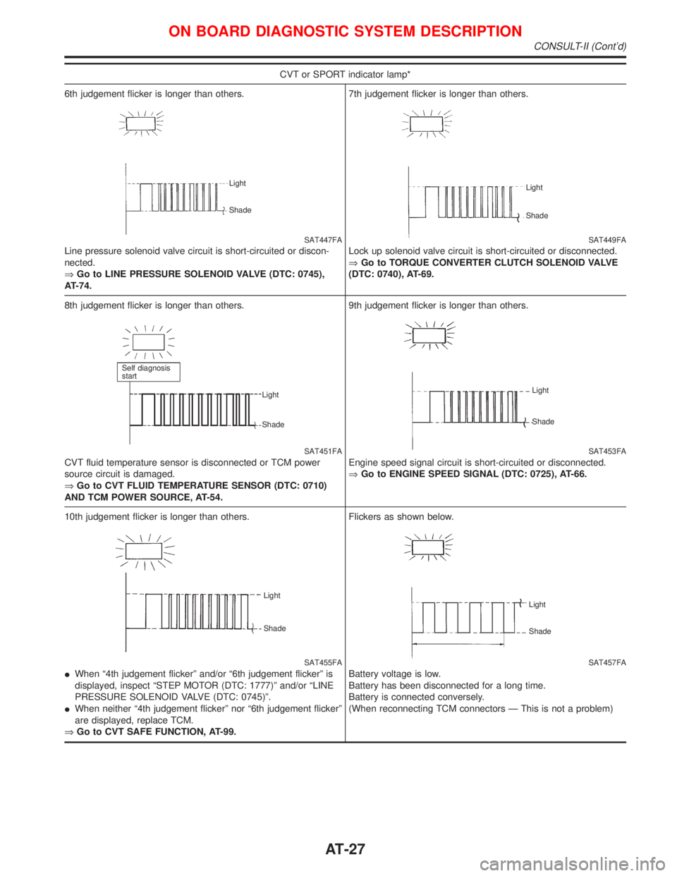
CVT or SPORT indicator lamp*
6th judgement flicker is longer than others.
SAT447FA
Line pressure solenoid valve circuit is short-circuited or discon-
nected.
ÞGo to LINE PRESSURE SOLENOID VALVE (DTC: 0745),
AT-74.
Light
Shade
7th judgement flicker is longer than others.
SAT449FA
Lock up solenoid valve circuit is short-circuited or disconnected.
ÞGo to TORQUE CONVERTER CLUTCH SOLENOID VALVE
(DTC: 0740), AT-69.
Light
Shade
8th judgement flicker is longer than others.
SAT451FA
CVT fluid temperature sensor is disconnected or TCM power
source circuit is damaged.
ÞGo to CVT FLUID TEMPERATURE SENSOR (DTC: 0710)
AND TCM POWER SOURCE, AT-54.
Self diagnosis
start
Light
Shade
9th judgement flicker is longer than others.
SAT453FA
Engine speed signal circuit is short-circuited or disconnected.
ÞGo to ENGINE SPEED SIGNAL (DTC: 0725), AT-66.
Light
Shade
10th judgement flicker is longer than others.
SAT455FA Light
Shade
IWhen ª4th judgement flickerº and/or ª6th judgement flickerº is
displayed, inspect ªSTEP MOTOR (DTC: 1777)º and/or ªLINE
PRESSURE SOLENOID VALVE (DTC: 0745)º.
IWhen neither ª4th judgement flickerº nor ª6th judgement flickerº
are displayed, replace TCM.
ÞGo to CVT SAFE FUNCTION, AT-99.Flickers as shown below.
SAT457FA
Battery voltage is low.
Battery has been disconnected for a long time.
Battery is connected conversely.
(When reconnecting TCM connectors Ð This is not a problem)
Light
Shade
ON BOARD DIAGNOSTIC SYSTEM DESCRIPTION
CONSULT-II (Cont'd)
AT-27