Page 119 of 2267

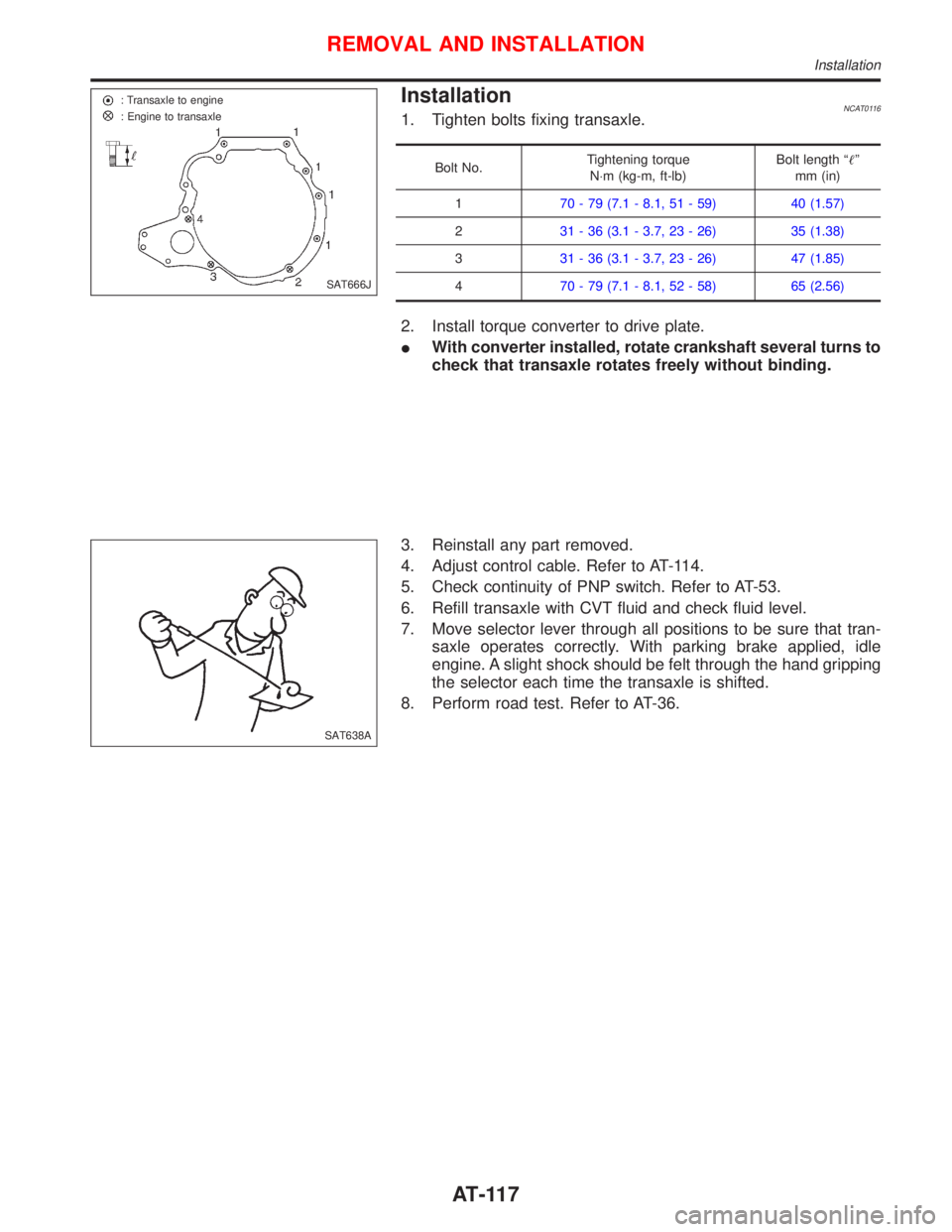
InstallationNCAT01161. Tighten bolts fixing transaxle.
Bolt No.Tightening torque
N×m (kg-m, ft-lb)Bolt length ªº
mm (in)
170 - 79 (7.1 - 8.1, 51 - 59) 40 (1.57)
231 - 36 (3.1 - 3.7, 23 - 26) 35 (1.38)
331 - 36 (3.1 - 3.7, 23 - 26) 47 (1.85)
470 - 79 (7.1 - 8.1, 52 - 58) 65 (2.56)
2. Install torque converter to drive plate.
IWith converter installed, rotate crankshaft several turns to
check that transaxle rotates freely without binding.
3. Reinstall any part removed.
4. Adjust control cable. Refer to AT-114.
5. Check continuity of PNP switch. Refer to AT-53.
6. Refill transaxle with CVT fluid and check fluid level.
7. Move selector lever through all positions to be sure that tran-
saxle operates correctly. With parking brake applied, idle
engine. A slight shock should be felt through the hand gripping
the selector each time the transaxle is shifted.
8. Perform road test. Refer to AT-36.
SAT666J : Transaxle to engine
: Engine to transaxle
SAT638A
REMOVAL AND INSTALLATION
Installation
AT-117
Page 121 of 2267
Components
NAT311 Fluid level gauge
Fluid charging pipe
5.0 - 6.8 (0.5 - 0.7, 44 - 60)
PNP SW5.0 - 6.8
(0.5 - 0.7, 44 - 60)
Dropping resistor
Secondary pulley speed sensor
5.0 - 6.8
(0.5 - 0.7, 44 - 60)
Speedometer pinion
O-ring
O-ringDifferential
oil seal
Torque converter
Input shaft O-ring
Oil pump
oil seal
CVT assy
Oil pan installation bolt (18)
6.9 - 8.8 (0.7 - 0.9, 61 - 78)
: N´m (kg-m, in-lb)
: N´m (kg-m, ft-lb)
: CVT fluid NS-1Oil panMagnetDrain bolt
30 - 39 (3.0 - 4.0, 22 - 29)
Gasket
Oil pan gasket
4.5 - 5.7 (0.45 - 0.59, 40 - 50)Tube (inlet)
40-58
(4.0 - 6.0,
30 - 43)
Copper washer
4.5 - 5.7
(0.45 - 0.59, 40 - 50) Tube (outlet)
4.5 - 5.7 (0.45 - 0.59, 40 - 50)Copper washer40 - 58 (4.0 - 6.0, 30 - 43)Primary pulley
speed sensor
5.0 - 6.8 (0.5 - 0.7, 44 - 60)
O-ring
O-ring
4.5 - 5.7 (0.45 - 0.59, 40 - 50)
Differential
oil seal
SEC. 310×311×312×319
REMOVAL AND INSTALLATION
Components
AT-119
Page 122 of 2267
General SpecificationsNCAT0179
EngineSR20DE
Automatic transaxle modelRE0F06A
Automatic transaxle assembly Model code number 8E020
Transaxle gear ratioD range Variable
Reverse 1.586
Final drive 5.473
Recommended fluidNissan CVT fluid NS-1*1
Fluid capacity8.1(7-1/8 Imp qt)
*1: Refer to MA section (ªFluids and Lubricantsº, ªRECOMMENDED FLUIDS AND LUBRICANTSº).
Any other fluid will damage the CVT.
Stall RevolutionNCAT0181
Engine Stall revolution rpm
(SR20DE) 2,350 - 2,850
Line PressureNCAT0182
Engine speed
rpmLine pressure MPa (kg/cm2, psi)
R position D position L position
Idle 0.6 (6.1, 87)
Stall 4.1 (42, 595)
Removal and InstallationNCAT0197Unit: mm (in)
Distance between end of converter housing and torque converter 15.9 (0.626) or more
SERVICE DATA AND SPECIFICATIONS (SDS)
General Specifications
AT-120
Page 125 of 2267

Supplemental Restraint System (SRS) ªAIR
BAGº and ªSEAT BELT PRE-TENSIONERº
The Supplemental Restraint System such as ªAIR BAGº and ªSEAT BELT PRE-TENSIONERº used along
with a seat belt, helps to reduce the risk or severity of injury to the driver and front passenger for certain
types of collision. The SRS system composition which is available to NISSAN MODEL P11 is as follows (The
composition varies according to the destination and optional equipment.):
lFor a frontal collision
The Supplemental Restraint System consists of driver air bag module (located in the center of the
steering wheel), front passenger air bag module (located on the instrument panel on passenger side),
front seat belt pre-tensioners, a diagnosis sensor unit, warning lamp, wiring harness and spiral cable.
lFor a side collision
The Supplemental Restraint System consists of front side air bag module (located in the outer side of
front seat), side air bag (satellite) sensor, diagnosis sensor unit (one of components of air bags for a
frontal collision), wiring harness, warning lamp (one of components of air bags for a frontal collision).
Information necessary to service the system safely is included in theRS sectionof this Service Manual.
WARNING:
lTo avoid rendering the SRS inoperative, which could increase the risk of personal injury or death
in the event of a collision which would result in air bag inflation, all maintenance should be per-
formed by an authorized NISSAN dealer.
lImproper maintenance, including incorrect removal and installation of the SRS, can lead to per-
sonal injury caused by unintentional activation of the system. For removal of Spiral Cable and
Air Bag Module, see the RS section.
lDo not use electrical test equipment on any circuit related to the SRS unless instructed to in this
Service Manual. Spiral cable and wiring harnesses covered with yellow insulation tape either just
before the harness connectors or for the complete harness are related to the SRS.
Precautions for Brake System
lRecommended fluid is brake fluid ªDOT 4º.
lNever reuse drained brake fluid.
lBe careful not to splash brake fluid on painted areas.
lTo clean or wash all parts of master cylinder, disc brake
caliper and wheel cylinder, use clean brake fluid.
lNever use mineral oils such as gasoline or kerosene.
They will ruin rubber parts of the hydraulic system.
lUse flare nut wrench when removing and installing brake
tube.
lAlways torque brake lines when installing.
lBurnish the brake contact surfaces after refinishing or
replacing rotors, after replacing pads, or if a soft pedal
occurs at very low mileage.
Refer to ªBrake Burnishing Procedureº, ªCheck and
Adjustmentº, BR-7.
WARNING:
lClean brake pads with a waste cloth, then wipe with a
dust collector.
SBR686C Commercial service tool
PRECAUTIONS
BR-3
Page 127 of 2267
Commercial Service Tools
Tool name Description
p1Flare nut crows foot
p2Torque wrench
NT360
Removing and installing each brake piping
a: 10 mm (0.39 in)
Brake fluid pressure
gauge
NT151
Measuring brake fluid pressure
PRECAUTIONS AND PREPARATION
BR-5
Page 139 of 2267
Installation
CAUTION:
lRefill with new brake fluid ªDOT 4º.
lNever reuse drained brake fluid.
1. Place master cylinder onto brake booster and secure mount-
ing nuts lightly.
2. Torque mounting nuts.
: 14 - 17 N´m (1.5 - 1.7 kg-m, 11 - 12 ft-lb)
3. Fill up reservoir tank with new brake fluid.
4. Plug all ports on master cylinder with fingers to prevent air
suction while releasing brake pedal.
5. Have driver depress brake pedal slowly several times until no
air comes out of master cylinder.
6. Fit brake lines to master cylinder.
7. Tighten flare nuts.
: 15 - 18 N´m (1.5 - 1.8 kg-m, 11 - 13 ft-lb)
8. Connect fluid level connector.
9. Bleed air from brake system. Refer to ªBleeding Brake
Systemº, BR-8.
SBR236E
MASTER CYLINDER
BR-17
Page 146 of 2267
1. Remove master cylinder reservoir cap.
2. Remove lower pin bolt.
3. Open cylinder body upward. Then remove pad retainers, and
inner and outer shims.
Standard pad thickness:
11 mm (0.43 in)
Pad wear limit:
2.0 mm (0.079 in)
Carefully monitor brake fluid level because brake fluid will
return to reservoir when pushing back piston.
Removal
WARNING:
Clean brake pads with a vacuum dust collector to minimize
the hazard of airborne materials.
CAUTION:
Suspend caliper assembly with wire so as not to stretch
brake hose.
Remove torque member fixing bolts and connecting bolt.
It is not necessary to remove connecting bolt except for
disassembly or replacement of caliper assembly.
NBR156
SBR079B Wire
NBR159
FRONT DISC BRAKE
Pad Replacement (Cont'd)
BR-24
Page 149 of 2267
REMOVAL
1. Remove the housing retaining spring.
2. Wipe away any dirt from the guide pins between the torque
member and the cylinder body.
3. Pull out the protective caps from the guide sleeves.
4. Usea7-mmALLEN key to unscrew the guide pins
from the torque member.
5. Partially remove the guide pins from the guide sleeve.
6. Pull the cylinder body manually towards the outer side of the
vehicle so that the piston is slightly pressed back.
7. Remove the cylinder body and hang it on a wire in the wheel
arch in a suitable position.
Make sure there is no strain on the brake hose piping.
8. Remove the brake pad on the piston side from the piston.
9. Remove the second brake pad from the torque member.
NBR292 Spring Cylinder bodyTorque member lug.Torque member lug Locating
holes
NBR300 Protective
caps
NBR290
Wire
Spring
FRONT DISC BRAKESR20DE - M/T
Pad Replacement (Cont'd)
BR-27