Page 966 of 2267
Diagnostic ProcedureNCEC0126
1 RETIGHTEN GROUND SCREWS
1. Turn ignition switch ªOFFº.
2. Loosen and retighten engine ground screws.
SEF202X
©GO TO 2.
2 RETIGHTEN HEATED OXYGEN SENSOR 1 (FRONT)
Loosen and retighten heated oxygen sensor 1 (front).
Tightening torque:
40-60N×m (4.1 - 6.1 kg-m, 30 - 44 ft-lb)
©GO TO 3.
3 CHECK EXHAUST AIR LEAK
1. Start engine and run it at idle.
2. Listen for an exhaust air leak before three way catalyst.
SEF099P
OK or NG
OK©GO TO 4.
NG©Repair or replace.
4 CHECK FOR INTAKE AIR LEAK
Listen for an intake air leak after the mass air flow sensor.
OK or NG
OK©GO TO 5.
NG©Repair or replace.
Intake manifold
collector
Engine
ground
DTC P0133 HEATED OXYGEN SENSOR 1
(FRONT) (RESPONSE MONITORING)SR20DE
Diagnostic Procedure
EC-166
Page 973 of 2267

Diagnostic ProcedureNCEC0134
1 RETIGHTEN HEATED OXYGEN SENSOR 1 (FRONT)
Loosen and retighten heated oxygen sensor 1 (front).
Tightening torque:
40-60N×m (4.1 - 6.1 kg-m, 30 - 44 ft-lb)
©GO TO 2.
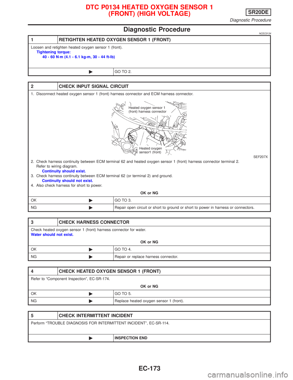
2 CHECK INPUT SIGNAL CIRCUIT
1. Disconnect heated oxygen sensor 1 (front) harness connector and ECM harness connector.
SEF207X2. Check harness continuity between ECM terminal 62 and heated oxygen sensor 1 (front) harness connector terminal 2.
Refer to wiring diagram.
Continuity should exist.
3. Check harness continuity between ECM terminal 62 (or terminal 2) and ground.
Continuity should not exist.
4. Also check harness for short to power.
OK or NG
OK©GO TO 3.
NG©Repair open circuit or short to ground or short to power in harness or connectors.
3 CHECK HARNESS CONNECTOR
Check heated oxygen sensor 1 (front) harness connector for water.
Water should not exist.
OK or NG
OK©GO TO 4.
NG©Repair or replace harness connector.
4 CHECK HEATED OXYGEN SENSOR 1 (FRONT)
Refer to ªComponent Inspectionº, EC-SR-174.
OK or NG
OK©GO TO 5.
NG©Replace heated oxygen sensor 1 (front).
5 CHECK INTERMITTENT INCIDENT
Perform ªTROUBLE DIAGNOSIS FOR INTERMITTENT INCIDENTº, EC-SR-114.
©INSPECTION END
Heated oxygen sensor 1
(front) harness connector
Heated oxygen
sensor1 (front)
DTC P0134 HEATED OXYGEN SENSOR 1
(FRONT) (HIGH VOLTAGE)SR20DE
Diagnostic Procedure
EC-173
Page 1187 of 2267

Trouble Diagnoses
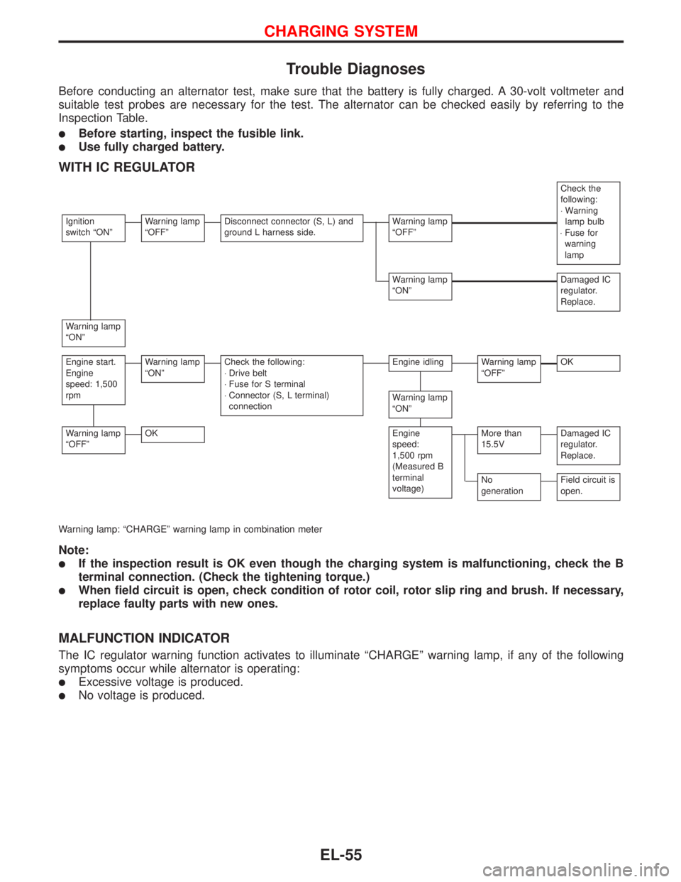
Before conducting an alternator test, make sure that the battery is fully charged. A 30-volt voltmeter and
suitable test probes are necessary for the test. The alternator can be checked easily by referring to the
Inspection Table.
�Before starting, inspect the fusible link.
�Use fully charged battery.
WITH IC REGULATOR
Check the
following:
⋅Warning
lamp bulb
⋅Fuse for
warning
lamp
Ignition
switch“ON”Warning lamp
“OFF”Disconnect connector (S, L) and
ground L harness side.Warning lamp
“OFF”
Warning lamp
“ON”Damaged IC
regulator.
Replace.
Warning lamp
“ON”
Engine start.
Engine
speed: 1,500
rpmWarning lamp
“ON”Check the following:
⋅Drive belt
⋅Fuse for S terminal
⋅Connector (S, L terminal)
connectionEngine idlingWarning lamp
“OFF”OK
Warning lamp
“ON”
Warning lamp
“OFF”OKEngine
speed:
1,500 rpm
(Measured B
terminal
voltage)More than
15.5VDamaged IC
regulator.
Replace.
No
generationField circuit is
open.
Warning lamp:“CHARGE”warning lamp in combination meter
Note:
�If the inspection result is OK even though the charging system is malfunctioning, check the B
terminal connection. (Check the tightening torque.)
�When field circuit is open, check condition of rotor coil, rotor slip ring and brush. If necessary,
replace faulty parts with new ones.
MALFUNCTION INDICATOR
The IC regulator warning function activates to illuminate“CHARGE”warning lamp, if any of the following
symptoms occur while alternator is operating:
�Excessive voltage is produced.
�No voltage is produced.
CHARGING SYSTEM
EL-55
Page 1322 of 2267
Removal and Installation
WIPER ARMS
1. Prior to wiper arm installation, turn on wiper switch to oper-
ate wiper motor and then turn it“OFF”(Auto Stop).
2. Lift the blade up and then set it down onto glass surface. Set
the blade center to clearance“C”immediately before tight-
ening nut.
3. Eject washer fluid. Turn on wiper switch to operate wiper
motor and then turn it“OFF”.
4. Ensure that wiper blades stop within clearance“C”.
Clearance“C”: 19 - 33 mm (0.75 - 1.30 in)
�Tighten windshield wiper arm nuts to specified torque.
:21-26N·m (2.1 - 2.7 kg-m, 15 - 20 ft-lb)
�Before reinstalling wiper arm, clean up the pivot area as
illustrated. This will reduce possibility of wiper arm
looseness.
NEL310 Clearance“C”
(Passenger side)
Clearance“C”
(Driver side)
Cowl top seal
SEL024J
FRONT WIPER AND WASHER
EL-190
Page 1329 of 2267
Removal and Installation
WIPER ARM
1. Prior to wiper arm installation, turn on wiper switch to oper-
ate wiper motor and then turn it off (Auto Stop).
2. Lift the blade up and then set it down onto glass surface. Set
the blade center before tightening nut.
3. Eject washer fluid. Turn on wiper switch to operate wiper
motor and then turn it off.
4. Ensure that wiper blade stops in the correct position.
�Tighten windshield wiper arm nut to specified torque.
:13-18N·m (1.4 - 1.8 kg-m, 10 - 13 ft-lb)
�Before reinstalling wiper arm, clean up the pivot area as
illustrated. This will reduce possibility of wiper arm
looseness.
Washer Nozzle Adjustment
�Adjust washer nozzle with suitable tool as shown in the fig-
ure at left.
Adjustable range: ±10°(In any direction)
Wagon60 (2.4)
170.3 (6.7)
Unit: mm (in) Sedan
Molding
edge
Hatchback
Back
door
side
66 (2.6)
YEL456B
SEL024J
NEL314 Suitable tool
Max. 10°
Nozzle hole bore diameter
1.0 mm (0.039 in)
REAR WIPER AND WASHER
EL-197
Page 1545 of 2267

Parts Requiring Angular Tightening
ISome important engine parts are tightened using an angular-
tightening method rather than a torque setting method.
IIf these parts are tightened using a torque setting method,
dispersal of the tightening force (axial bolt force) will be two or
three times that of the dispersal produced by using the correct
angular-tightening method.
IAlthough the torque setting values (described in this manual)
are equivalent to those used when bolts and nuts are tightened
with an angular-tightening method, they should be used for
reference only.
ITo assure the satisfactory maintenance of the engine, bolts
and nuts must be tightened using an angular-tightening
method.
IBefore tightening the bolts and nuts, ensure that the thread
and seating surfaces are clean and then coated with engine oil.
IThe bolts and nuts which require the angular-tightening
method are as follows:
(1) Cylinder head bolts ..... SR, CD, QG
(2) Main bearing cap bolts ..... SR
(3) Connecting rod cap nuts ..... SR, QG
Liquid Gasket Application Procedure
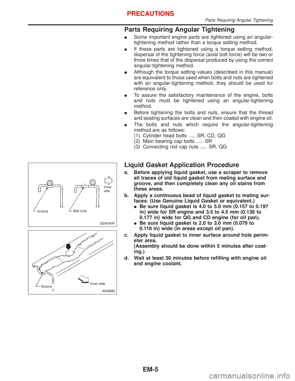
a. Before applying liquid gasket, use a scraper to remove
all traces of old liquid gasket from mating surface and
groove, and then completely clean any oil stains from
these areas.
b. Apply a continuous bead of liquid gasket to mating sur-
faces. (Use Genuine Liquid Gasket or equivalent.)
IBe sure liquid gasket is 4.0 to 5.0 mm (0.157 to 0.197
in) wide for SR engine and 3.5 to 4.5 mm (0.138 to
0.177 in) wide for QG and CD engine (for oil pan).
IBe sure liquid gasket is 2.0 to 3.0 mm (0.079 to
0.118 in) wide (in areas except oil pan).
c. Apply liquid gasket to inner surface around hole perim-
eter area.
(Assembly should be done within 5 minutes after coat-
ing.)
d. Wait at least 30 minutes before refilling with engine oil
and engine coolant.
SEM164FInner
side
GrooveBolt hole
AEM080 Inner side
Groove
PRECAUTIONS
Parts Requiring Angular Tightening
EM-5
Page 1565 of 2267

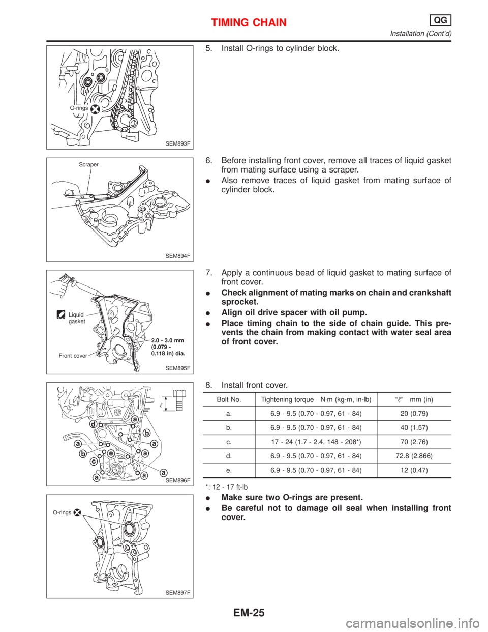
5. Install O-rings to cylinder block.
6. Before installing front cover, remove all traces of liquid gasket
from mating surface using a scraper.
IAlso remove traces of liquid gasket from mating surface of
cylinder block.
7. Apply a continuous bead of liquid gasket to mating surface of
front cover.
ICheck alignment of mating marks on chain and crankshaft
sprocket.
IAlign oil drive spacer with oil pump.
IPlace timing chain to the side of chain guide. This pre-
vents the chain from making contact with water seal area
of front cover.
8. Install front cover.
Bolt No. Tightening torque N×m (kg-m, in-lb) ªº mm (in)
a. 6.9 - 9.5 (0.70 - 0.97, 61 - 84) 20 (0.79)
b. 6.9 - 9.5 (0.70 - 0.97, 61 - 84) 40 (1.57)
c. 17 - 24 (1.7 - 2.4, 148 - 208*) 70 (2.76)
d. 6.9 - 9.5 (0.70 - 0.97, 61 - 84) 72.8 (2.866)
e. 6.9 - 9.5 (0.70 - 0.97, 61 - 84) 12 (0.47)
*: 12 - 17 ft-lb
IMake sure two O-rings are present.
IBe careful not to damage oil seal when installing front
cover.
SEM893F O-rings
SEM894F Scraper
SEM895F 2.0 - 3.0 mm
(0.079 -
0.118 in) dia.
Liquid
gasket
Front cover
SEM896F
SEM897F O-rings
TIMING CHAINQG
Installation (Cont'd)
EM-25
Page 1567 of 2267
21. Install camshaft sprocket bolts to correct torque.
IApply new engine oil to bolt threads and seat surface.
22. Install chain tensioner.
IBefore installing chain tensioner, insert a suitable pin into
pin hole of chain tensioner.
IAfter installing chain tensioner, remove the pin.
23. Install timing chain guide.
24. Install cylinder head front cover.
IApply liquid gasket to cylinder head front cover.
IUse Genuine Liquid Gasket or equivalent.
25. Install camshaft position sensor (PHASE).
26. Before installing rocker cover, apply a continuous bead of li-
quid gasket to mating surface of cylinder head.
SEM906F
SEM907F Chain guide
Chain tensioner
Stopper pin
SEM887F Cylinder head front cover
2.0 - 3.0 mm
(0.079 -
0.118 in) dia.
SEM889F Camshaft position
sensor (PHASE)
O-ring
SEM888F Liquid gasket
3 mm (0.12 in) dia.
Cylinder head
Cylinder head front cover
TIMING CHAINQG
Installation (Cont'd)
EM-27