Page 1688 of 2267
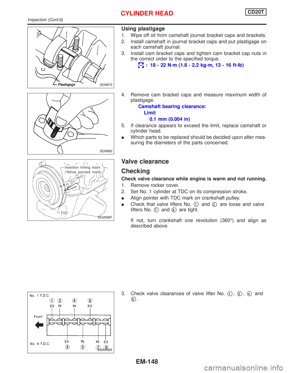
Using plastigage
1. Wipe off oil from camshaft journal bracket caps and brackets.
2. Install camshaft in journal bracket caps and put plastigage on
each camshaft journal.
3. Install cam bracket caps and tighten cam bracket cap nuts in
the correct order to the specified torque.
: 18 - 22 N´m (1.8 - 2.2 kg-m, 13 - 16 ft-lb)
4. Remove cam bracket caps and measure maximum width of
plastigage.
Camshaft bearing clearance:
Limit
0.1 mm (0.004 in)
5. If clearance appears to exceed the limit, replace camshaft or
cylinder head.
IWhich parts to be replaced should be decided upon after mea-
suring the diameters of the parts concerned.
Valve clearance
Checking
Check valve clearance while engine is warm and not running.
1. Remove rocker cover.
2. Set No. 1 cylinder at TDC on its compression stroke.
IAlign pointer with TDC mark on crankshaft pulley.
ICheck that valve lifters No.
p1andp2are loose and valve
lifters No.
p7andp8are tight.
If not, turn crankshaft one revolution (360É) and align as
described above.
3. Check valve clearances of valve lifter No.
p1,p2,p4and
p6.
SEM879
SEM880
SEM369F
SMA406A
CYLINDER HEADCD20T
Inspection (Cont'd)
EM-148
Page 1691 of 2267
Assembly
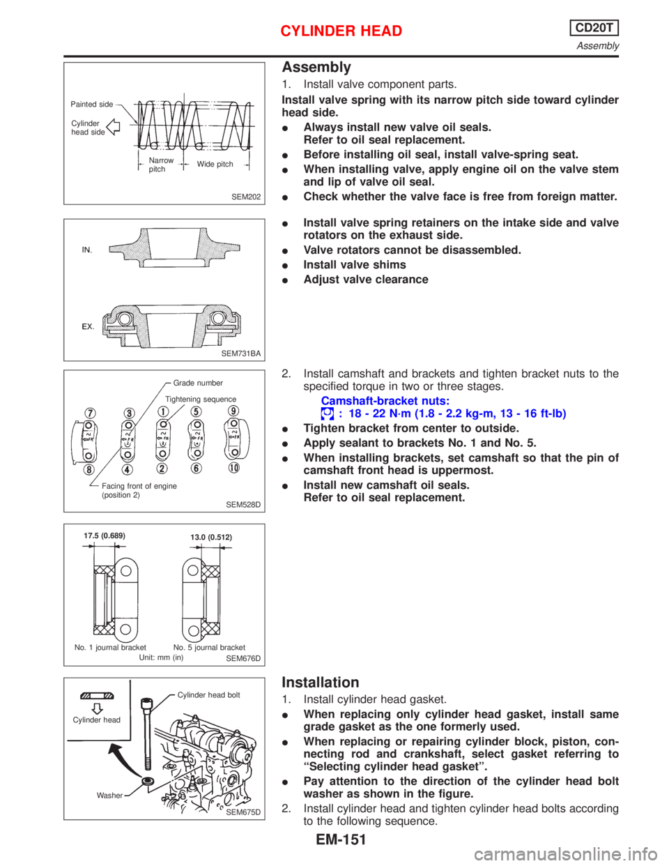
1. Install valve component parts.
Install valve spring with its narrow pitch side toward cylinder
head side.
IAlways install new valve oil seals.
Refer to oil seal replacement.
IBefore installing oil seal, install valve-spring seat.
IWhen installing valve, apply engine oil on the valve stem
and lip of valve oil seal.
ICheck whether the valve face is free from foreign matter.
IInstall valve spring retainers on the intake side and valve
rotators on the exhaust side.
IValve rotators cannot be disassembled.
IInstall valve shims
IAdjust valve clearance
2. Install camshaft and brackets and tighten bracket nuts to the
specified torque in two or three stages.
Camshaft-bracket nuts:
: 18 - 22 N´m (1.8 - 2.2 kg-m, 13 - 16 ft-lb)
ITighten bracket from center to outside.
IApply sealant to brackets No. 1 and No. 5.
IWhen installing brackets, set camshaft so that the pin of
camshaft front head is uppermost.
IInstall new camshaft oil seals.
Refer to oil seal replacement.
Installation
1. Install cylinder head gasket.
IWhen replacing only cylinder head gasket, install same
grade gasket as the one formerly used.
IWhen replacing or repairing cylinder block, piston, con-
necting rod and crankshaft, select gasket referring to
ªSelecting cylinder head gasketº.
IPay attention to the direction of the cylinder head bolt
washer as shown in the figure.
2. Install cylinder head and tighten cylinder head bolts according
to the following sequence.
SEM202 Painted side
Cylinder
head side
Narrow
pitchWide pitch
SEM731BA
SEM528D Grade number
Tightening sequence
Facing front of engine
(position 2)
SEM676D 17.5 (0.689)
13.0 (0.512)
No. 1 journal bracket No. 5 journal bracket
Unit: mm (in)
SEM675D Cylinder headCylinder head bolt
Washer
CYLINDER HEADCD20T
Assembly
EM-151
Page 1714 of 2267
Reboring
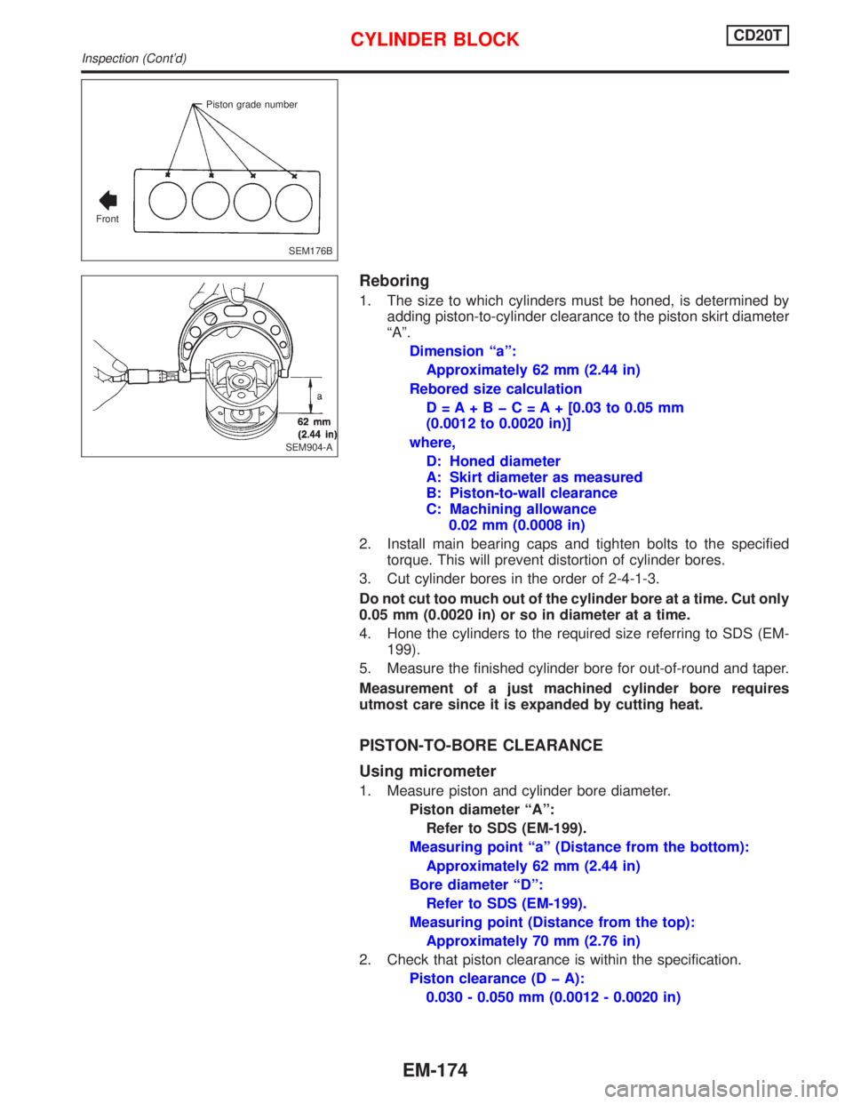
1. The size to which cylinders must be honed, is determined by
adding piston-to-cylinder clearance to the piston skirt diameter
ªAº.
Dimension ªaº:
Approximately 62 mm (2.44 in)
Rebored size calculation
D=A+BþC=A+[0.03 to 0.05 mm
(0.0012 to 0.0020 in)]
where,
D: Honed diameter
A: Skirt diameter as measured
B: Piston-to-wall clearance
C: Machining allowance
0.02 mm (0.0008 in)
2. Install main bearing caps and tighten bolts to the specified
torque. This will prevent distortion of cylinder bores.
3. Cut cylinder bores in the order of 2-4-1-3.
Do not cut too much out of the cylinder bore at a time. Cut only
0.05 mm (0.0020 in) or so in diameter at a time.
4. Hone the cylinders to the required size referring to SDS (EM-
199).
5. Measure the finished cylinder bore for out-of-round and taper.
Measurement of a just machined cylinder bore requires
utmost care since it is expanded by cutting heat.
PISTON-TO-BORE CLEARANCE
Using micrometer
1. Measure piston and cylinder bore diameter.
Piston diameter ªAº:
Refer to SDS (EM-199).
Measuring point ªaº (Distance from the bottom):
Approximately 62 mm (2.44 in)
Bore diameter ªDº:
Refer to SDS (EM-199).
Measuring point (Distance from the top):
Approximately 70 mm (2.76 in)
2. Check that piston clearance is within the specification.
Piston clearance (D þ A):
0.030 - 0.050 mm (0.0012 - 0.0020 in)
SEM176B Piston grade number
Front
SEM904-A
CYLINDER BLOCKCD20T
Inspection (Cont'd)
EM-174
Page 1744 of 2267
Precautions
lWhen installing each rubber part, final tightening must
be carried out under unladen condition* with tires on
ground.
*: Fuel, radiator coolant and engine oil full. Spare tire,
jack, hand tools and mats in designated positions.
lWhen removing each suspension part, check wheel
alignment and adjust if necessary.
lUse Tool when removing or installing brake tubes.
lAlways torque brake lines when installing.
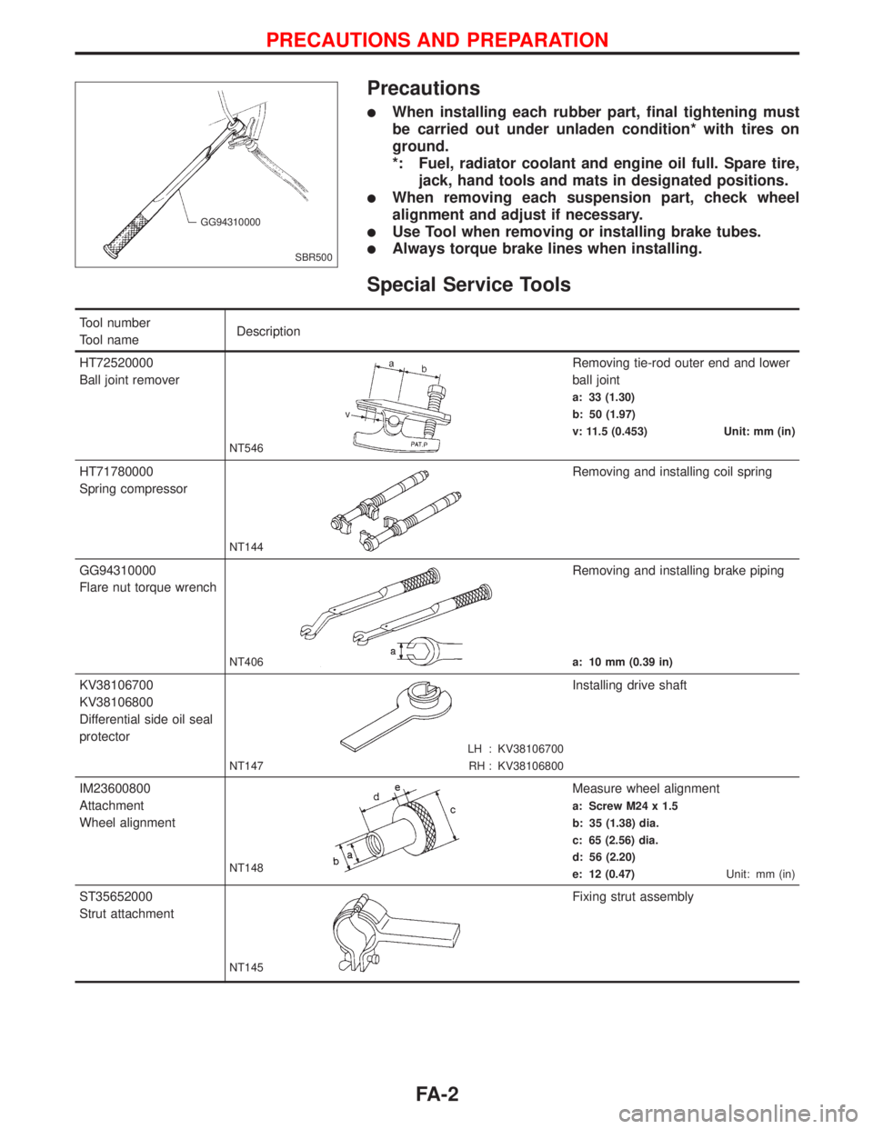
Special Service Tools
Tool number
Tool nameDescription
HT72520000
Ball joint remover
NT546
Removing tie-rod outer end and lower
ball joint
a: 33 (1.30)
b: 50 (1.97)
v: 11.5 (0.453) Unit: mm (in)
HT71780000
Spring compressor
NT144
Removing and installing coil spring
GG94310000
Flare nut torque wrench
NT406
Removing and installing brake piping
a: 10 mm (0.39 in)
KV38106700
KV38106800
Differential side oil seal
protector
LH : KV38106700
RH : KV38106800 NT147
Installing drive shaft
IM23600800
Attachment
Wheel alignment
NT148
Measure wheel alignment
a: Screw M24 x 1.5
b: 35 (1.38) dia.
c: 65 (2.56) dia.
d: 56 (2.20)
e: 12 (0.47)Unit: mm (in)
ST35652000
Strut attachment
NT145
Fixing strut assembly
SBR500 GG94310000
PRECAUTIONS AND PREPARATION
FA-2
Page 1747 of 2267
Front Axle and Front Suspension Parts
Check front axle and front suspension parts for excessive play,
cracks, wear or other damage.
lShake each front wheel to check for excessive play.
lEnsure that new cotter pins are used, and are correctly fit-
ted.
lRetighten all axle and suspension nuts and bolts to the speci-
fied torque.
Tightening torque:
Refer to FRONT SUSPENSION, FA-26.
lCheck strut (shock absorber) for oil leakage or other dam-
age.
lCheck suspension ball joint for grease leakage and ball joint
dust cover for cracks or other damage.
If ball joint dust cover is cracked or damaged, replace trans-
verse link.
SMA525A
SMA614
NFA029
SMA113
SFA911A.SFA911A
ON-VEHICLE SERVICE
FA-5
Page 1750 of 2267
b. Adjust toe-in by screwing tie-rods in and out.
Standard length ªLº:
Refer to ST section (ªGeneral Specificationsº,
ªSDSº).
c. Tighten lock nuts to specified torque.
: 38 - 47 N´m (3.9 - 4.7 kg-m, 28 - 34 ft-lb)
FRONT WHEEL TURNING ANGLE
1. Set wheels in straight-ahead position. Then move vehicle
forward until front wheels rest on turning radius gauge prop-
erly.
2. Rotate steering wheel all the way right and left; measure
turning angle.
lOn power steering models, turn steering wheel to full lock
and apply force (at circumference of steering wheel) of 98 to
147 N (10 to 15 kg, 22 to 33 lb) with engine at idle.
Do not hold the steering wheel at full lock for more than
15 seconds.
Wheel turning angle (Full turn):
Refer to SDS, FA-35.
Drive Shaft
Check for grease leakage or other damage.
SFA486A Lock nut
SFA439B
.SFA914A
ON-VEHICLE SERVICE
Front Wheel Alignment (Cont'd)
FA-8
Page 1774 of 2267

Transverse Link and Lower Ball Joint
REMOVAL AND INSTALLATION
lRemove tension rod, ball joint and transverse link assembly.
lDuring installation, final tightening must be done at curb
weight with tires on ground.
lAfter installation, check wheel alignment.
Refer to ªFront Wheel Alignmentº, ªON-VEHICLE SER-
VICEº, FA-6.
INSPECTION
Transverse link
lCheck transverse link for damage, cracks or deformation.
Replace it if necessary.
lCheck rubber bushing for damage, cracks and deformation.
Replace transverse link if necessary.
Lower ball joint
lCheck ball joint for excessive play. Replace transverse link
assembly if any of the following exists:
lBall stud is worn.
lJoint is hard to swing.
lPlay in axial direction is excessive.
Before checking, turn ball joint at least 10 revolutions so that
ball joint is properly broken in.
Swinging force ªAº:
(measuring point: cotter pin hole of ball stud)
7.8 - 57.9 N (0.8 - 5.9 kg, 1.8 - 13.0 lb)
Turning torque ªBº:
0.5 - 3.4 (5 - 35 kg-cm, 4.3 - 30.4 in-lb)
Vertical end play ªCº:
0mm(0in)
lCheck dust cover for damage. Replace it and cover clamp if
necessary.
Stabilizer Bar
REMOVAL AND INSTALLATION
CAUTION:
Ð For models with xenon headlamps only
lWhen removing or installing stabilizer bar, take care not
to damage headlamp leveling sensor.
lAfter installation of the stabilizer bar, the headlamp sen-
sor has to be recalibrated. Refer to EL-section.
lRemove stabilizer bar.
NFA036
SFA858A A
B
C
.SFA925A
FRONT SUSPENSION
FA-32
Page 1777 of 2267
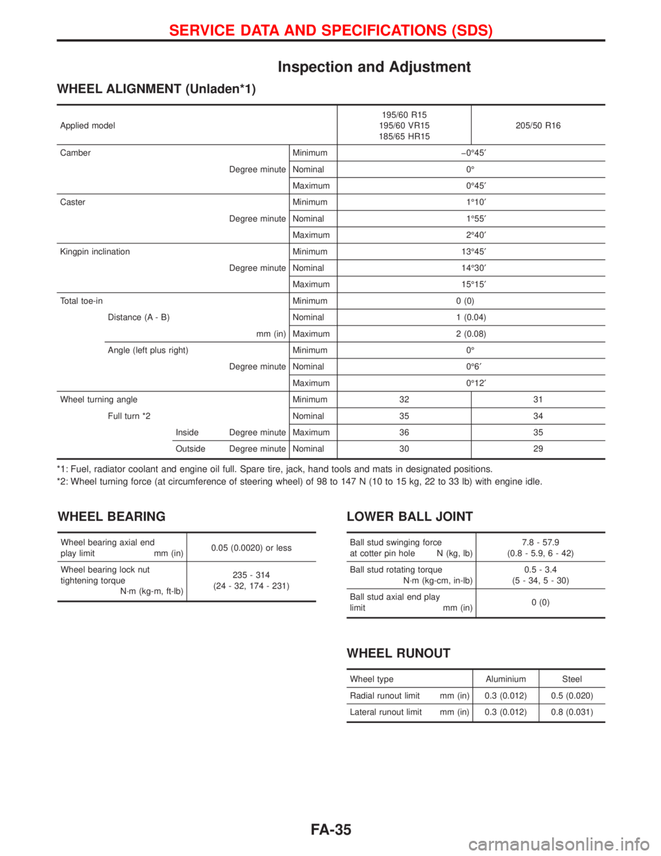
Inspection and Adjustment
WHEEL ALIGNMENT (Unladen*1)
Applied model195/60 R15
195/60 VR15
185/65 HR15205/50 R16
Camber Minimum þ0É45¢
Degree minute Nominal 0É
Maximum 0É45¢
Caster Minimum 1É10¢
Degree minute Nominal 1É55¢
Maximum 2É40¢
Kingpin inclination Minimum 13É45¢
Degree minute Nominal 14É30¢
Maximum 15É15¢
Total toe-in Minimum 0 (0)
Distance (A - B) Nominal 1 (0.04)
mm (in) Maximum 2 (0.08)
Angle (left plus right) Minimum 0É
Degree minute Nominal 0É6¢
Maximum 0É12¢
Wheel turning angle Minimum 32 31
Full turn *2 Nominal 35 34
Inside Degree minute Maximum 36 35
Outside Degree minute Nominal 30 29
*1: Fuel, radiator coolant and engine oil full. Spare tire, jack, hand tools and mats in designated positions.
*2: Wheel turning force (at circumference of steering wheel) of 98 to 147 N (10 to 15 kg, 22 to 33 lb) with engine idle.
WHEEL BEARING
Wheel bearing axial end
play limit mm (in)0.05 (0.0020) or less
Wheel bearing lock nut
tightening torque
N´m (kg-m, ft-lb)235 - 314
(24 - 32, 174 - 231)
LOWER BALL JOINT
Ball stud swinging force
at cotter pin hole N (kg, lb)7.8 - 57.9
(0.8 - 5.9, 6 - 42)
Ball stud rotating torque
N´m (kg-cm, in-lb)0.5 - 3.4
(5 - 34, 5 - 30)
Ball stud axial end play
limit mm (in)0 (0)
WHEEL RUNOUT
Wheel type Aluminium Steel
Radial runout limit mm (in) 0.3 (0.012) 0.5 (0.020)
Lateral runout limit mm (in) 0.3 (0.012) 0.8 (0.031)
SERVICE DATA AND SPECIFICATIONS (SDS)
FA-35