Page 2050 of 2267
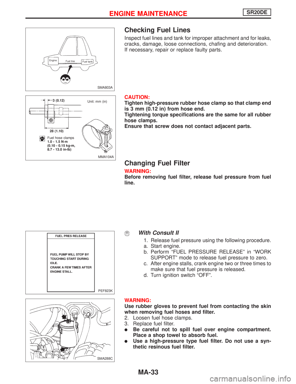
Checking Fuel Lines
Inspect fuel lines and tank for improper attachment and for leaks,
cracks, damage, loose connections, chafing and deterioration.
If necessary, repair or replace faulty parts.
CAUTION:
Tighten high-pressure rubber hose clamp so that clamp end
is 3 mm (0.12 in) from hose end.
Tightening torque specifications are the same for all rubber
hose clamps.
Ensure that screw does not contact adjacent parts.
Changing Fuel Filter
WARNING:
Before removing fuel filter, release fuel pressure from fuel
line.
With Consult II
1. Release fuel pressure using the following procedure.
a. Start engine.
b. Perform“FUEL PRESSURE RELEASE”in“WORK
SUPPORT”mode to release fuel pressure to zero.
c. After engine stalls, crank engine two or three times to
make sure that fuel pressure is released.
d. Turn ignition switch“OFF”.
WARNING:
Use rubber gloves to prevent fuel from contacting the skin
when removing fuel hoses and filter.
2. Loosen fuel hose clamps.
3. Replace fuel filter.
�Be careful not to spill fuel over engine compartment.
Place a shop towel to absorb fuel.
�Use a high-pressure type fuel filter. Do not use a syn-
thetic resinous fuel filter.
SMA803A
Engine
Fuel line
Fuel tank
MMA104A 3 (0.12)
28 (1.10)
Fuel hose clamps
1.0 - 1.5 N·m
(0.10 - 0.15 kg-m,
8.7 - 13.0 in-lb)Unit: mm (in)
PEF823K
.SMA288C
ENGINE MAINTENANCESR20DE
MA-33
Page 2070 of 2267
Balancing Wheels
Wheel balance (maximum allowable unbalance):
10 g (0.35 oz) at rim flange.
Tire balance weight:
5 - 60 g (0.18 - 2.12 oz)
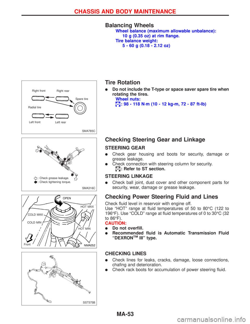
Tire Rotation
�Do not include the T-type or space saver spare tire when
rotating the tires.
Wheel nuts:
:98-118N·m (10 - 12 kg-m, 72 - 87 ft-lb)
Checking Steering Gear and Linkage
STEERING GEAR
�Check gear housing and boots for security, damage or
grease leakage.
�Check connection with steering column for security.
: Refer to ST section.
STEERING LINKAGE
�Check ball joint, dust cover and other component parts for
security, wear, damage or grease leakage.
Checking Power Steering Fluid and Lines
Check fluid level in reservoir with engine off.
Use“HOT”range at fluid temperatures of 50 to 80°C (122 to
196°F). Use“COLD”range at fluid temperatures of 0 to 30°C (32
to 86°F).
CAUTION:
�Do not overfill.
�Recommended fluid is Automatic Transmission Fluid
“DEXRONTMIII”type.
CHECKING LINES
�Check lines for leaks, cracks, damage, loose connections,
chafing and deterioration.
�Check rack boots for accumulation of power steering fluid.
SMA785C Right front
Right rear
Radial tire
Left front
Left rearSpare tire
SMA316C : Check grease leakage.
: Check tightening torque.
NMA052 OPEN
.HOT MAX
.HOT MIN COLD MAX
COLD MIN
Front
SST575B
CHASSIS AND BODY MAINTENANCE
MA-53
Page 2080 of 2267
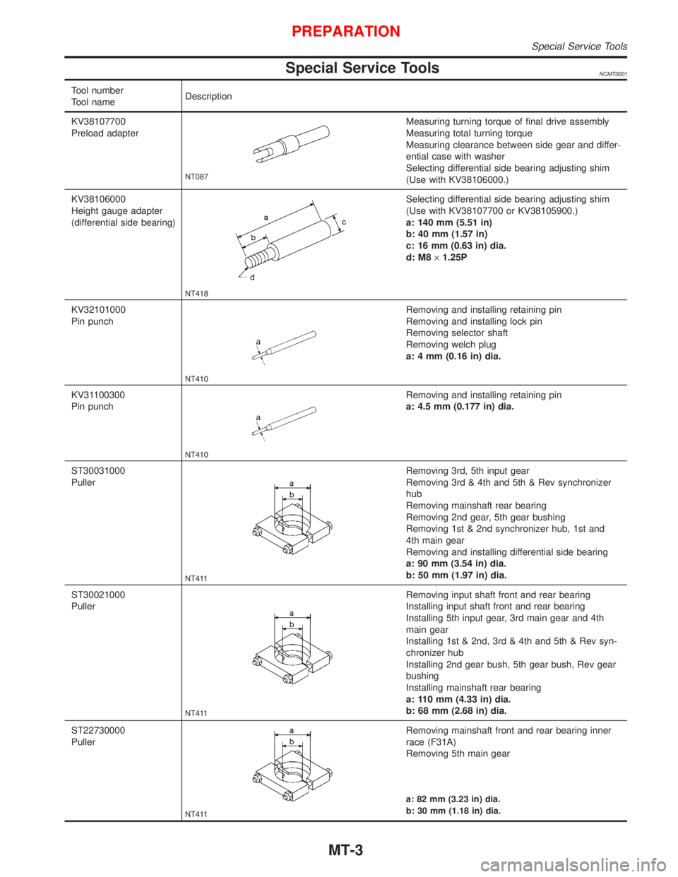
Special Service ToolsNCMT0001
Tool number
Tool nameDescription
KV38107700
Preload adapter
NT087
Measuring turning torque of final drive assembly
Measuring total turning torque
Measuring clearance between side gear and differ-
ential case with washer
Selecting differential side bearing adjusting shim
(Use with KV38106000.)
KV38106000
Height gauge adapter
(differential side bearing)
NT418
Selecting differential side bearing adjusting shim
(Use with KV38107700 or KV38105900.)
a: 140 mm (5.51 in)
b: 40 mm (1.57 in)
c: 16 mm (0.63 in) dia.
d: M8´1.25P
KV32101000
Pin punch
NT410
Removing and installing retaining pin
Removing and installing lock pin
Removing selector shaft
Removing welch plug
a: 4 mm (0.16 in) dia.
KV31100300
Pin punch
NT410
Removing and installing retaining pin
a: 4.5 mm (0.177 in) dia.
ST30031000
Puller
NT411
Removing 3rd, 5th input gear
Removing 3rd & 4th and 5th & Rev synchronizer
hub
Removing mainshaft rear bearing
Removing 2nd gear, 5th gear bushing
Removing 1st & 2nd synchronizer hub, 1st and
4th main gear
Removing and installing differential side bearing
a: 90 mm (3.54 in) dia.
b: 50 mm (1.97 in) dia.
ST30021000
Puller
NT411
Removing input shaft front and rear bearing
Installing input shaft front and rear bearing
Installing 5th input gear, 3rd main gear and 4th
main gear
Installing 1st & 2nd, 3rd & 4th and 5th & Rev syn-
chronizer hub
Installing 2nd gear bush, 5th gear bush, Rev gear
bushing
Installing mainshaft rear bearing
a: 110 mm (4.33 in) dia.
b: 68 mm (2.68 in) dia.
ST22730000
Puller
NT411
Removing mainshaft front and rear bearing inner
race (F31A)
Removing 5th main gear
a: 82 mm (3.23 in) dia.
b: 30 mm (1.18 in) dia.
PREPARATION
Special Service Tools
MT-3
Page 2089 of 2267
14. Remove bolts securing transaxle.
15. Lower transaxle while supporting it with a jack.
InstallationNCMT0007S02
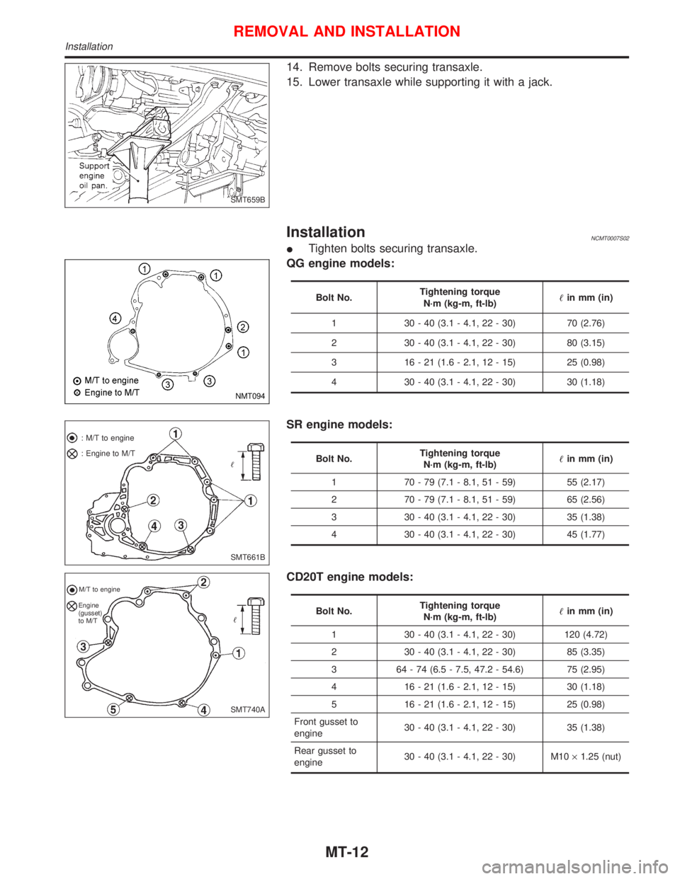
ITighten bolts securing transaxle.
QG engine models:
Bolt No.Tightening torque
N´m (kg-m, ft-lb)in mm (in)
1 30 - 40 (3.1 - 4.1, 22 - 30) 70 (2.76)
2 30 - 40 (3.1 - 4.1, 22 - 30) 80 (3.15)
3 16 - 21 (1.6 - 2.1, 12 - 15) 25 (0.98)
4 30 - 40 (3.1 - 4.1, 22 - 30) 30 (1.18)
SR engine models:
Bolt No.Tightening torque
N´m (kg-m, ft-lb)in mm (in)
1 70 - 79 (7.1 - 8.1, 51 - 59) 55 (2.17)
2 70 - 79 (7.1 - 8.1, 51 - 59) 65 (2.56)
3 30 - 40 (3.1 - 4.1, 22 - 30) 35 (1.38)
4 30 - 40 (3.1 - 4.1, 22 - 30) 45 (1.77)
CD20T engine models:
Bolt No.Tightening torque
N´m (kg-m, ft-lb)in mm (in)
1 30 - 40 (3.1 - 4.1, 22 - 30) 120 (4.72)
2 30 - 40 (3.1 - 4.1, 22 - 30) 85 (3.35)
3 64 - 74 (6.5 - 7.5, 47.2 - 54.6) 75 (2.95)
4 16 - 21 (1.6 - 2.1, 12 - 15) 30 (1.18)
5 16 - 21 (1.6 - 2.1, 12 - 15) 25 (0.98)
Front gusset to
engine30 - 40 (3.1 - 4.1, 22 - 30) 35 (1.38)
Rear gusset to
engine30 - 40 (3.1 - 4.1, 22 - 30) M10´1.25 (nut)
SMT659B
NMT094
SMT661B : M/T to engine
: Engine to M/T
SMT740A
M/T to engine
Engine
(gusset)
to M/T
REMOVAL AND INSTALLATION
Installation
MT-12
Page 2116 of 2267
Differential Side Bearing Preload
If any of the following parts are replaced, adjust differential side
bearing preload.
IDifferential case
IDifferential side bearing
IClutch housing
ITransmission case
1. Remove differential side bearing outer race (transmission case
side) and shim.
2. Reinstall differential side bearing outer race without shim.
3. Install final drive assembly on clutch housing.
4. Install transmission case on clutch housing.
ITighten transmission case fixing bolts to the specified
torque.
5. Set dial indicator on front end of differential case.
6. Insert Tool all the way into differential side gear.
7. Move Tool up and down and measure dial indicator deflection.
8. Select shim of proper thickness using SDS table as a guide.
Differential side bearing adjusting shims:
Refer to SDS MT-88.
SMT645 ST33290001
SMT646A
SMT454 KV38106000
KV38107700
ADJUSTMENTRS5F32A
Differential Side Bearing Preload
MT-39
Page 2117 of 2267
9. Install selected shim and differential side bearing outer race.
10. Check differential side bearing turning torque.
a. Install final drive assembly on clutch housing.
b. Install transmission case on clutch housing.
ITighten transmission case fixing bolts to the specified
torque. Page MT-15
c. Measure turning torque of final drive assembly.
Turning torque of final drive assembly
(New bearing):
2.9 - 6.9 N´m (30 - 70 kg-cm, 26 - 61 in-lb)
IWhen old bearing is used again, turning torque will be
slightly less than the above.
IMake sure torque is close to the specified range.
IChanges in turning torque of final drive assembly per
revolution should be within 1.0 N´m (10 kg-cm, 8.7 in-lb)
without binding.
SMT600 KV38107700
ADJUSTMENTRS5F32A
Differential Side Bearing Preload (Cont'd)
MT-40
Page 2151 of 2267
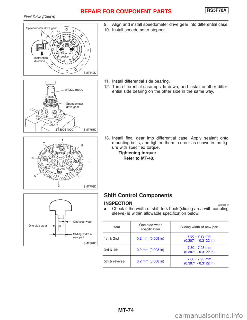
9. Align and install speedometer drive gear into differential case.
10. Install speedometer stopper.
11. Install differential side bearing.
12. Turn differential case upside down, and install another differ-
ential side bearing on the other side in the same way.
13. Install final gear into differential case. Apply sealant onto
mounting bolts, and tighten them in order as shown in the fig-
ure with specified torque.
Tightening torque:
Refer to MT-48.
Shift Control Components
INSPECTIONNCMT0019
ICheck if the width of shift fork hook (sliding area with coupling
sleeve) is within allowable specification below.
ItemOne-side wear
specificationSliding width of new part
1st & 2nd0.2 mm (0.008 in)7.80 - 7.93 mm
(0.3071 - 0.3122 in)
3rd & 4th0.2 mm (0.008 in)7.80 - 7.93 mm
(0.3071 - 0.3122 in)
5th & reverse0.2 mm (0.008 in)7.80 - 7.93 mm
(0.3071 - 0.3122 in)
SMT842D Speedometer drive gear
Installation
directionAlignment
position
SMT751D Speedometer
drive gear
SMT752D
SMT801D One-side wear
Sliding width of
new part One-side wear
REPAIR FOR COMPONENT PARTSRS5F70A
Final Drive (Cont'd)
MT-74
Page 2154 of 2267
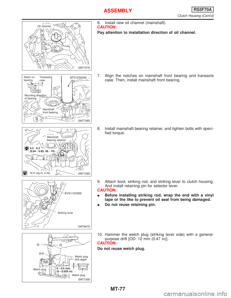
6. Install new oil channel (mainshaft).
CAUTION:
Pay attention to installation direction of oil channel.
7. Align the notches on mainshaft front bearing and transaxle
case. Then, install mainshaft front bearing.
8. Install mainshaft bearing retainer, and tighten bolts with speci-
fied torque.
9. Attach boot, striking rod, and striking lever to clutch housing.
And install retaining pin for selector lever.
CAUTION:
IBefore installing striking rod, wrap the end with a vinyl
tape or the like to prevent oil seal from being damaged.
IDo not reuse retaining pin.
10. Hammer the welch plug (striking lever side) with a general-
purpose drift [OD: 12 mm (0.47 in)].
CAUTION:
Do not reuse welch plug.
SMT727D Oil channel
SMT728D Notch on
bearingTransaxle
case
Mounting direction
of bearing
Mainshaft
front bearing
SMT729D Mainshaft
bearing retainer
6.3 - 8.3
(0.64 - 0.85, 56 - 74)
N´m (kg-m, in-lb)
SMT667D Striking lever
SMT730D Drift
Welch plug0 - 0.5 mm
(0 - 0.020 in)
Welch plugWelch plug
drift depth
ASSEMBLYRS5F70A
Clutch Housing (Cont'd)
MT-77