Page 2174 of 2267
Rear Axle and Rear Suspension Parts
Check axle and suspension parts for excessive play, wear or
damage.
lShake each rear wheel to check for excessive play.
lRetighten all nuts and bolts to the specified torque.
Tightening torque:
Refer to REAR SUSPENSION (RA-9).
lCheck shock absorber for oil leakage or other damage.
Rear Wheel Bearing
lCheck axial end play.
Axial end play:
0.00 mm (0.0000 in)
lCheck that wheel hub bearings operate smoothly.
lCheck tightening torque of wheel bearing lock nut.
: 187 - 255 N´m (19 - 26 kg-m, 138 - 188 ft-lb)
lReplace wheel bearing assembly if there is axial end play
or wheel bearing does not turn smoothly.
Refer to REAR AXLE Ð Wheel Hub (RA-7).
SMA525A
NRA005
SMA113
SRA690A
ON-VEHICLE SERVICE
RA-5
Page 2176 of 2267
Wheel Hub
p1Spindle
p2Baffle plate
p3Wheel hub bearing
p4Wheel bearing lock nut
p5Cotter pinp6Hub cap
p7ABS sensor
REMOVAL
CAUTION:
lBefore removing the rear wheel hub assembly, discon-
nect the ABS wheel sensor from the assembly. Then
move it away from the hub assembly. Failure to do so
may result in damage to the sensor wires and the sen-
sor becoming inoperative.
lWheel hub bearing does not require maintenance. If any
of the following symptoms are noted, replace wheel hub
bearing assembly.
lGrowling noise is emitted from wheel hub bearing during
operation.
lWheel hub bearing drags or turns roughly. This occurs when
turning hub by hand after bearing lock nut is tightened to
specified torque.
NRA015
SEC. 430
Front
187 - 255
(19 - 26, 138 - 188)
22-29
(2.3 - 2.9, 17 - 21)25 - 33 (2.6 - 3.3, 19 - 24)
: Do not re-use
: N´m (kg-m, ft-lb)
REAR AXLE
RA-7
Page 2179 of 2267

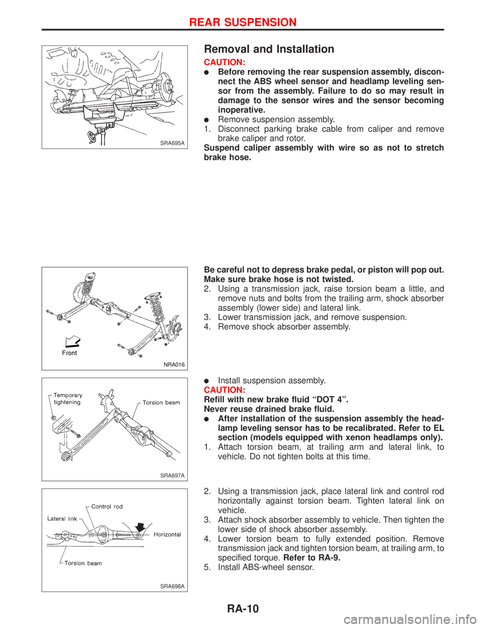
Removal and Installation
CAUTION:
lBefore removing the rear suspension assembly, discon-
nect the ABS wheel sensor and headlamp leveling sen-
sor from the assembly. Failure to do so may result in
damage to the sensor wires and the sensor becoming
inoperative.
lRemove suspension assembly.
1. Disconnect parking brake cable from caliper and remove
brake caliper and rotor.
Suspend caliper assembly with wire so as not to stretch
brake hose.
Be careful not to depress brake pedal, or piston will pop out.
Make sure brake hose is not twisted.
2. Using a transmission jack, raise torsion beam a little, and
remove nuts and bolts from the trailing arm, shock absorber
assembly (lower side) and lateral link.
3. Lower transmission jack, and remove suspension.
4. Remove shock absorber assembly.
lInstall suspension assembly.
CAUTION:
Refill with new brake fluid ªDOT 4º.
Never reuse drained brake fluid.
lAfter installation of the suspension assembly the head-
lamp leveling sensor has to be recalibrated. Refer to EL
section (models equipped with xenon headlamps only).
1. Attach torsion beam, at trailing arm and lateral link, to
vehicle. Do not tighten bolts at this time.
2. Using a transmission jack, place lateral link and control rod
horizontally against torsion beam. Tighten lateral link on
vehicle.
3. Attach shock absorber assembly to vehicle. Then tighten the
lower side of shock absorber assembly.
4. Lower torsion beam to fully extended position. Remove
transmission jack and tighten torsion beam, at trailing arm, to
specified torque.Refer to RA-9.
5. Install ABS-wheel sensor.
SRA695A
NRA016
SRA697A
SRA698A
REAR SUSPENSION
RA-10
Page 2182 of 2267
2. Temporarily install lateral link and control rod on torsion
beam.
lWhen installing, place lateral link with the arrow topside.
3. Place lateral link and control rod horizontally against torsion
beam, and tighten to the specified torque.
4. Install torsion beam assembly. Refer to Removal and Instal-
lation in REAR SUSPENSION (RA-10).
SRA701A
SRA702A
REAR SUSPENSION
Torsion Beam, Lateral Link and Control Rod
(Cont'd)
RA-13
Page 2183 of 2267
General Specifications
Suspension type Multi-link beam suspension
Shock absorber type Double-acting hydraulic
Stabilizer Standard equipment
Inspection and Adjustment
WHEEL ALIGNMENT (Unladen*)
Camber Minimum þ2É9¢(þ2.15É)
Degree minute
(Decimal degree)Nominal þ1É24¢(þ1.4É)
Maximum þ0É39¢(þ0.65É)
Total toe-in Minimum þ1.8 (þ0.07)
Distance (AþB)
mm (in)Nominal 2.2 (0.09)
Maximum 6.2 (0.24)
Angle (left plus right) Minimum þ0É11¢24²(þ0.19É)
Degree minute
(Decimal degree)Nominal 0É12¢36²(0.21É)
Maximum 0É36¢36²(0.61É)
*: Fuel, radiator coolant and engine oil full. Spare tire, jack,
hand tools and mats in designated positions.
WHEEL BEARING
Wheel bearing axial end play
mm (in)0.0 (0.00)
Wheel bearing lock nut tighten-
ing torque
N´m (kg-m, ft-lb)187 - 255
(19 - 26, 138 - 188)
SERVICE DATA AND SPECIFICATIONS (SDS)
RA-14
Page 2246 of 2267
SPECIAL SERVICE TOOLS
Tool number
Tool nameDescription
KV48100700
Torque adapter
Measuring pinion rotating torque
HT72520000
Ball joint remover
Removing ball joint
ST27091000
Pressure gauge
Measuring oil pressure
KV48102500
Pressure gauge adapter
Measuring oil pressure
ST3127S000
p1GG91030000
Torque wrench
p2HT62940000
Socket adapter
p3HT62900000
Socket adapter
Measuring turning torque
PREPARATION
ST-3
Page 2247 of 2267

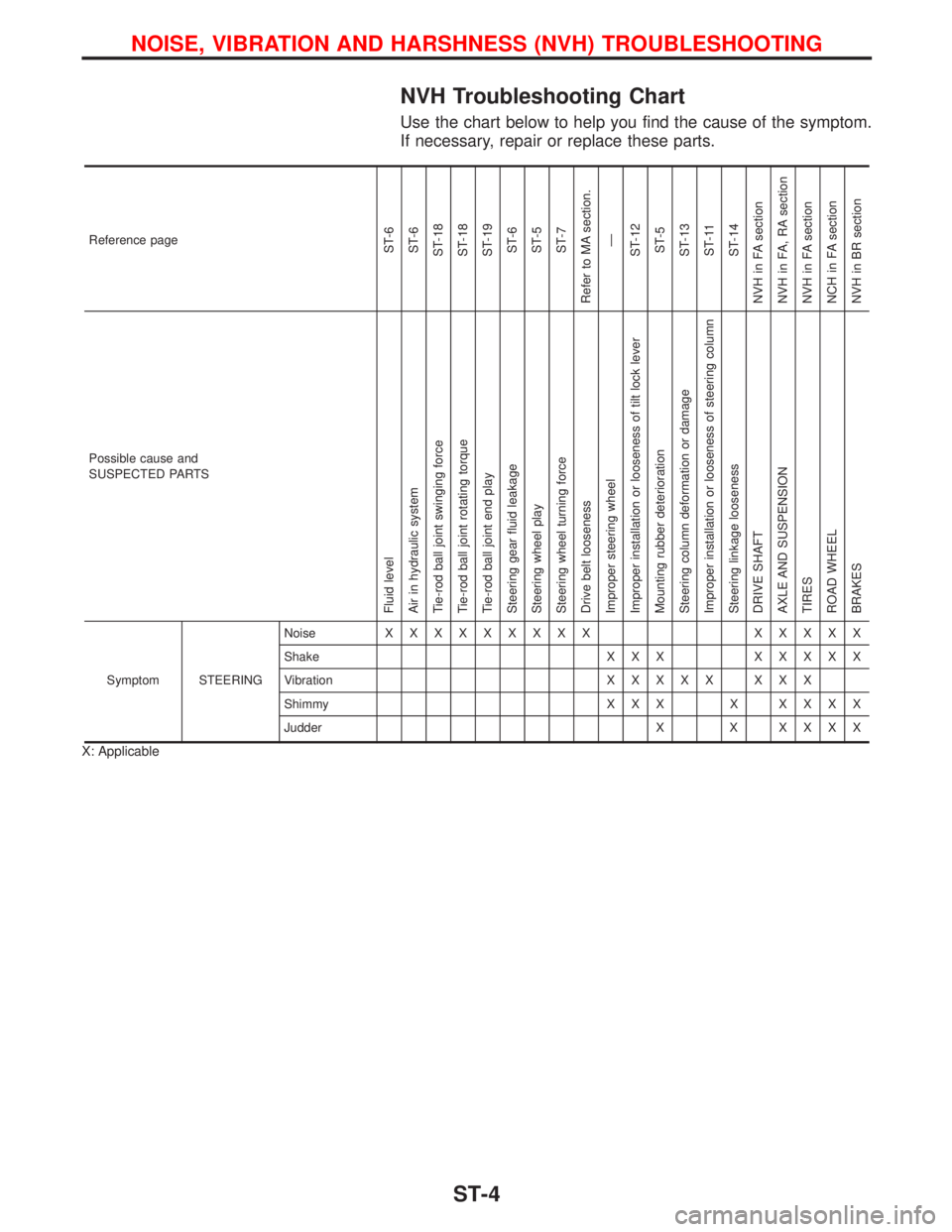
NVH Troubleshooting Chart
Use the chart below to help you find the cause of the symptom.
If necessary, repair or replace these parts.
Reference pageST-6
ST-6
ST-18
ST-18
ST-19
ST-6
ST-5
ST-7
Refer to MA section.
Ð
ST-12
ST-5
ST-13
ST-11
ST-14
NVH in FA section
NVH in FA, RA section
NVH in FA section
NCH in FA section
NVH in BR section
Possible cause and
SUSPECTED PARTS
Fluid level
Air in hydraulic system
Tie-rod ball joint swinging force
Tie-rod ball joint rotating torque
Tie-rod ball joint end play
Steering gear fluid leakage
Steering wheel play
Steering wheel turning force
Drive belt looseness
Improper steering wheel
Improper installation or looseness of tilt lock lever
Mounting rubber deterioration
Steering column deformation or damage
Improper installation or looseness of steering column
Steering linkage looseness
DRIVE SHAFT
AXLE AND SUSPENSION
TIRES
ROAD WHEEL
BRAKES
Symptom STEERINGNoiseXXXXXXXXX XXXXX
Shake X X XXXXXX
VibrationXXXXX XXX
Shimmy X X X XXXXX
Judder X XXXXX
X: Applicable
NOISE, VIBRATION AND HARSHNESS (NVH) TROUBLESHOOTING
ST-4
Page 2259 of 2267

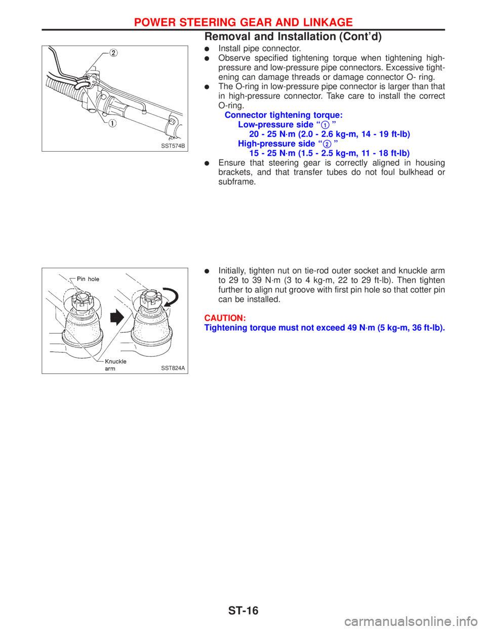
lInstall pipe connector.
lObserve specified tightening torque when tightening high-
pressure and low-pressure pipe connectors. Excessive tight-
ening can damage threads or damage connector O- ring.
lThe O-ring in low-pressure pipe connector is larger than that
in high-pressure connector. Take care to install the correct
O-ring.
Connector tightening torque:
Low-pressure side ª
p1º
20 - 25 N´m (2.0 - 2.6 kg-m, 14 - 19 ft-lb)
High-pressure side ª
p2º
15 - 25 N´m (1.5 - 2.5 kg-m, 11 - 18 ft-lb)
lEnsure that steering gear is correctly aligned in housing
brackets, and that transfer tubes do not foul bulkhead or
subframe.
lInitially, tighten nut on tie-rod outer socket and knuckle arm
to 29 to 39 N´m (3 to 4 kg-m, 22 to 29 ft-lb). Then tighten
further to align nut groove with first pin hole so that cotter pin
can be installed.
CAUTION:
Tightening torque must not exceed 49 N´m (5 kg-m, 36 ft-lb).
SST574B
SST824A
POWER STEERING GEAR AND LINKAGE
Removal and Installation (Cont'd)
ST-16