Page 2155 of 2267
11. Install selector, selector shaft, and selector shaft pin into clutch
housing.
12. Hammer the welch plug (selector shaft side) with a general-
purpose drift [OD: 12 mm (0.47 in)].
CAUTION:
Do not reuse welch plug.
13. Install selector leaf spring, return spring, steel ball, reverse
gate, selector arm, bushing, and return bearing. Then, tighten
two reamer bolts with specified torque.
CAUTION:
Use correct reamer bolts for each installation point, because
each bolt has a different length.
14. Install oil pocket.
SMT731D Selector shaft pin
Selector
Welch plug
Selector shaft
SMT732D Drift
Welch plug
0 - 0.5 mm
(0 - 0.020 in)Welch plug
drift depth
Welch plug
SMT733D Reamer bolt
(short)
Selector
leaf spring
Return
spring
Reverse
gate
Steel ballReamer bolt
(long)
Bushing
Return bearing
Selector
arm
SMT734D N´m
(kg-m, ft-lb)
16-21
(1.6 - 2.1, 12 - 15)
SMT735D Oil pocket
ASSEMBLYRS5F70A
Clutch Housing (Cont'd)
MT-78
Page 2156 of 2267
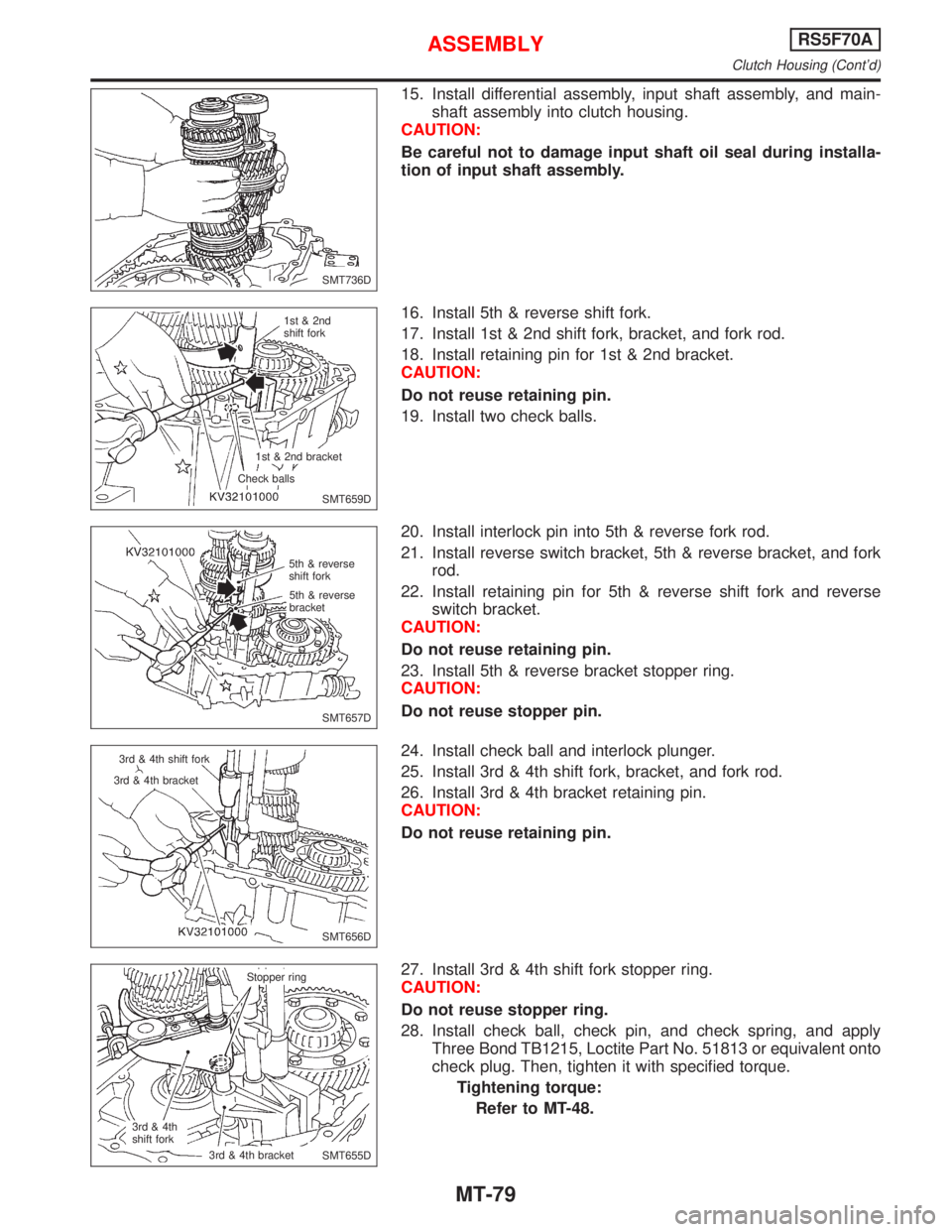
15. Install differential assembly, input shaft assembly, and main-
shaft assembly into clutch housing.
CAUTION:
Be careful not to damage input shaft oil seal during installa-
tion of input shaft assembly.
16. Install 5th & reverse shift fork.
17. Install 1st & 2nd shift fork, bracket, and fork rod.
18. Install retaining pin for 1st & 2nd bracket.
CAUTION:
Do not reuse retaining pin.
19. Install two check balls.
20. Install interlock pin into 5th & reverse fork rod.
21. Install reverse switch bracket, 5th & reverse bracket, and fork
rod.
22. Install retaining pin for 5th & reverse shift fork and reverse
switch bracket.
CAUTION:
Do not reuse retaining pin.
23. Install 5th & reverse bracket stopper ring.
CAUTION:
Do not reuse stopper pin.
24. Install check ball and interlock plunger.
25. Install 3rd & 4th shift fork, bracket, and fork rod.
26. Install 3rd & 4th bracket retaining pin.
CAUTION:
Do not reuse retaining pin.
27. Install 3rd & 4th shift fork stopper ring.
CAUTION:
Do not reuse stopper ring.
28. Install check ball, check pin, and check spring, and apply
Three Bond TB1215, Loctite Part No. 51813 or equivalent onto
check plug. Then, tighten it with specified torque.
Tightening torque:
Refer to MT-48.
SMT736D
SMT659D 1st & 2nd
shift fork
1st & 2nd bracket
Check balls
SMT657D 5th & reverse
shift fork
5th & reverse
bracket
SMT656D 3rd & 4th shift fork
3rd & 4th bracket
SMT655D Stopper ring
3rd & 4th
shift fork.3rd & 4th bracket
ASSEMBLYRS5F70A
Clutch Housing (Cont'd)
MT-79
Page 2158 of 2267
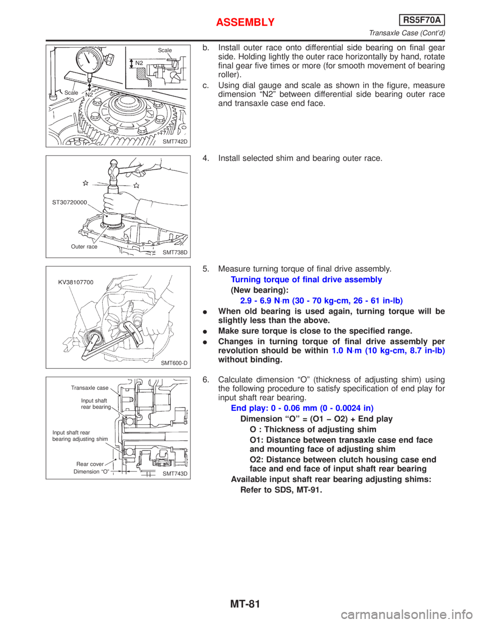
b. Install outer race onto differential side bearing on final gear
side. Holding lightly the outer race horizontally by hand, rotate
final gear five times or more (for smooth movement of bearing
roller).
c. Using dial gauge and scale as shown in the figure, measure
dimension ªN2º between differential side bearing outer race
and transaxle case end face.
4. Install selected shim and bearing outer race.
5. Measure turning torque of final drive assembly.
Turning torque of final drive assembly
(New bearing):
2.9 - 6.9 N×m (30 - 70 kg-cm, 26 - 61 in-lb)
IWhen old bearing is used again, turning torque will be
slightly less than the above.
IMake sure torque is close to the specified range.
IChanges in turning torque of final drive assembly per
revolution should be within1.0 N×m (10 kg-cm, 8.7 in-lb)
without binding.
6. Calculate dimension ªOº (thickness of adjusting shim) using
the following procedure to satisfy specification of end play for
input shaft rear bearing.
End play: 0 - 0.06 mm (0 - 0.0024 in)
Dimension ªOº = (O1 þ O2) + End play
O : Thickness of adjusting shim
O1: Distance between transaxle case end face
and mounting face of adjusting shim
O2: Distance between clutch housing case end
face and end face of input shaft rear bearing
Available input shaft rear bearing adjusting shims:
Refer to SDS, MT-91.
SMT742D ScaleScale
SMT738D Outer race
SMT600-D
SMT743D Transaxle case
Input shaft
rear bearing
Input shaft rear
bearing adjusting shim
Rear cover
Dimension ªOº
ASSEMBLYRS5F70A
Transaxle Case (Cont'd)
MT-81
Page 2160 of 2267
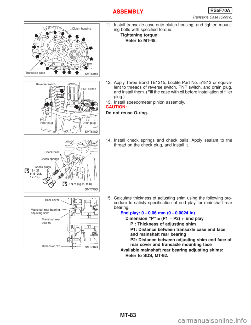
11. Install transaxle case onto clutch housing, and tighten mount-
ing bolts with specified torque.
Tightening torque:
Refer to MT-48.
12. Apply Three Bond TB1215, Loctite Part No. 51813 or equiva-
lent to threads of reverse switch, PNP switch, and drain plug,
and install them. (Fill the case with oil before installation of filler
plug.)
13. Install speedometer pinion assembly.
CAUTION:
Do not reuse O-ring.
14. Install check springs and check balls. Apply sealant to the
thread on the check plug, and install it.
15. Calculate thickness of adjusting shim using the following pro-
cedure to satisfy specification of end play for mainshaft rear
bearing.
End play: 0 - 0.06 mm (0 - 0.0024 in)
Dimension ªPº = (P1 þ P2) + End play
P : Thickness of adjusting shim
P1: Distance between transaxle case end face
and mainshaft rear bearing
P2: Distance between adjusting shim end face of
rear cover and transaxle mounting face
Available mainshaft rear bearing adjusting shims:
Refer to SDS, MT-92.
SMT649D Clutch housing
Transaxle case
SMT648D Reverse switch
PNP switch
Filler plug Drain plug
SMT749D Check balls
Check springs
Check plugs
16-22
(1.6 -2.2,
12 -16)
N´m (kg-m, ft-lb)
SMT746D Rear cover
Mainshaft rear bearing
adjusting shim
Mainshaft rear
bearing
Dimension ªPº
ASSEMBLYRS5F70A
Transaxle Case (Cont'd)
MT-83
Page 2162 of 2267
21. Install selected snap ring.
CAUTION:
Do not reuse snap ring.
22. Apply gear oil to rear cover O-ring, and install rear cover, side
cover gasket, and side cover. Then tighten mounting bolts with
specified torque.
Tightening torque:
Refer to MT-48.
CAUTION:
Do not reuse mounting bolts for rear cover and side cover.
SMT644D Snap ring
Rear cover
Side cover
ASSEMBLYRS5F70A
Transaxle Case (Cont'd)
MT-85
Page 2164 of 2267
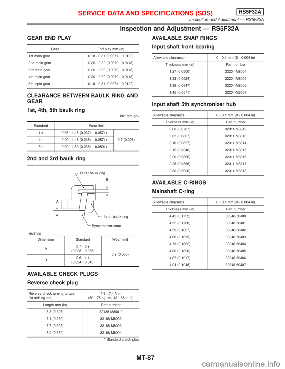
Inspection and Adjustment Ð RS5F32A
GEAR END PLAY
Gear End play mm (in)
1st main gear 0.18 - 0.31 (0.0071 - 0.0122)
2nd main gear 0.20 - 0.30 (0.0079 - 0.0118)
3rd main gear 0.20 - 0.30 (0.0079 - 0.0118)
4th main gear 0.20 - 0.30 (0.0079 - 0.0118)
5th input gear 0.18 - 0.31 (0.0071 - 0.0122)
CLEARANCE BETWEEN BAULK RING AND
GEAR
1st, 4th, 5th baulk ring
Unit: mm (in)
Standard Wear limit
1st 0.95 - 1.45 (0.0374 - 0.0571)
0.7 (0.028) 4th 0.90 - 1.45 (0.0354 - 0.0571)
5th 0.90 - 1.50 (0.0354 - 0.0591)
2nd and 3rd baulk ring
NMT026
Outer baulk ring
B
A
Inner baulk ring
Synchronizer cone
Dimension Standard Wear limit
A0.7 - 0.9
(0.028 - 0.035)
0.2 (0.008)
B0.6 - 1.1
(0.024 - 0.043)
AVAILABLE CHECK PLUGS
Reverse check plug
Reverse check turning torque
(At striking rod)4.9 - 7.4 N´m
(50 - 75 kg-cm, 43 - 65 in-lb)
Length mm (in) Part number
8.3 (0.327) 32188-M8001*
7.1 (0.280) 32188-M8002
7.7 (0.303) 32188-M8003
8.9 (0.350) 32188-M8004
* Standard check plug
AVAILABLE SNAP RINGS
Input shaft front bearing
Allowable clearance 0 - 0.1 mm (0 - 0.004 in)
Thickness mm (in) Part number
1.27 (0.0500) 32204-M8004
1.33 (0.0524) 32204-M8005
1.39 (0.0547) 32204-M8006
1.45 (0.0571) 32204-M8007
Input shaft 5th synchronizer hub
Allowable clearance 0 - 0.1 mm (0 - 0.004 in)
Thickness mm (in) Part number
2.00 (0.0787) 32311-M8812
2.05 (0.0807) 32311-M8813
2.10 (0.0827) 32311-M8814
2.15 (0.0846) 32311-M8815
2.20 (0.0866) 32311-M8816
2.25 (0.0886) 32311-M8817
2.30 (0.0906) 32311-M8818
AVAILABLE C-RINGS
Mainshaft C-ring
Allowable clearance 0 - 0.1 mm (0 - 0.004 in)
Thickness mm (in) Part number
4.45 (0.1752) 32348-50J00
4.52 (0.1780) 32348-50J01
4.59 (0.1807) 32348-50J02
4.66 (0.1835) 32348-50J03
4.73 (0.1862) 32348-50J04
4.80 (0.1890) 32348-50J05
4.87 (0.1917) 32348-50J06
4.94 (0.1945) 32348-50J07
SERVICE DATA AND SPECIFICATIONS (SDS)RS5F32A
Inspection and Adjustment Ð RS5F32A
MT-87
Page 2165 of 2267
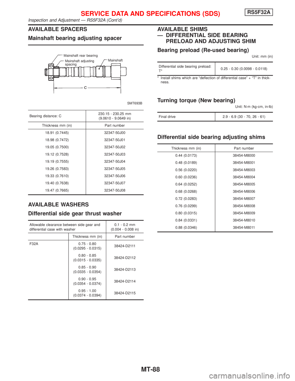
AVAILABLE SPACERS
Mainshaft bearing adjusting spacer
SMT693B Mainshaft rear bearing
Mainshaft adjusting
spacingMainshaft
Bearing distance: C230.15 - 230.25 mm
(9.0610 - 9.0649 in)
Thickness mm (in) Part number
18.91 (0.7445) 32347-50J00
18.98 (0.7472) 32347-50J01
19.05 (0.7500) 32347-50J02
19.12 (0.7528) 32347-50J03
19.19 (0.7555) 32347-50J04
19.26 (0.7583) 32347-50J05
19.33 (0.7610) 32347-50J06
19.40 (0.7638) 32347-50J07
19.47 (0.7665) 32347-50J08
AVAILABLE WASHERS
Differential side gear thrust washer
Allowable clearance between side gear and
differential case with washer0.1 - 0.2 mm
(0.004 - 0.008 in)
Thickness mm (in) Part number
F32A 0.75 - 0.80
(0.0295 - 0.0315)38424-D2111
0.80 - 0.85
(0.0315 - 0.0335)38424-D2112
0.85 - 0.90
(0.0335 - 0.0354)38424-D2113
0.90 - 0.95
(0.0354 - 0.0374)38424-D2114
0.95 - 1.00
(0.0374 - 0.0394)38424-D2115
AVAILABLE SHIMS
Ð DIFFERENTIAL SIDE BEARING
PRELOAD AND ADJUSTING SHIM
Bearing preload (Re-used bearing)
Unit: mm (in)
Differential side bearing preload:
T*0.25 - 0.30 (0.0098 - 0.0118)
* Install shims which are ªdeflection of differential caseº + ªTº in thick-
ness.
Turning torque (New bearing)
Unit: N´m (kg-cm, in-lb)
Final drive 2.9 - 6.9 (30 - 70, 26 - 61)
Differential side bearing adjusting shims
Thickness mm (in) Part number
0.44 (0.0173) 38454-M8000
0.48 (0.0189) 38454-M8001
0.56 (0.0220) 38454-M8003
0.60 (0.0236) 38454-M8004
0.64 (0.0252) 38454-M8005
0.68 (0.0268) 38454-M8006
0.72 (0.0283) 38454-M8007
0.76 (0.0299) 38454-M8008
0.80 (0.0315) 38454-M8009
0.84 (0.0331) 38454-M8010
0.88 (0.0346) 38454-M8011
SERVICE DATA AND SPECIFICATIONS (SDS)RS5F32A
Inspection and Adjustment Ð RS5F32A (Cont'd)
MT-88
Page 2171 of 2267
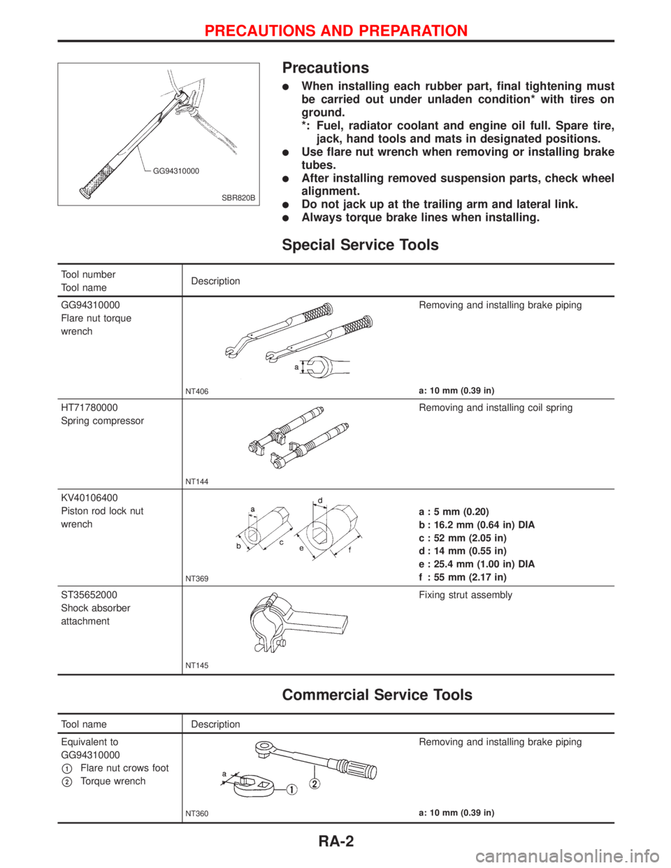
Precautions
lWhen installing each rubber part, final tightening must
be carried out under unladen condition* with tires on
ground.
*: Fuel, radiator coolant and engine oil full. Spare tire,
jack, hand tools and mats in designated positions.
lUse flare nut wrench when removing or installing brake
tubes.
lAfter installing removed suspension parts, check wheel
alignment.
lDo not jack up at the trailing arm and lateral link.
lAlways torque brake lines when installing.
Special Service Tools
Tool number
Tool nameDescription
GG94310000
Flare nut torque
wrench
NT406
Removing and installing brake piping
a: 10 mm (0.39 in)
HT71780000
Spring compressor
NT144
Removing and installing coil spring
KV40106400
Piston rod lock nut
wrench
NT369
a : 5 mm (0.20)
b : 16.2 mm (0.64 in) DIA
c : 52 mm (2.05 in)
d : 14 mm (0.55 in)
e : 25.4 mm (1.00 in) DIA
f : 55 mm (2.17 in)
ST35652000
Shock absorber
attachment
NT145
Fixing strut assembly
Commercial Service Tools
Tool name Description
Equivalent to
GG94310000
p1Flare nut crows foot
p2Torque wrench
NT360
Removing and installing brake piping
a: 10 mm (0.39 in)
SBR820B GG94310000
PRECAUTIONS AND PREPARATION
RA-2