Page 37 of 2267
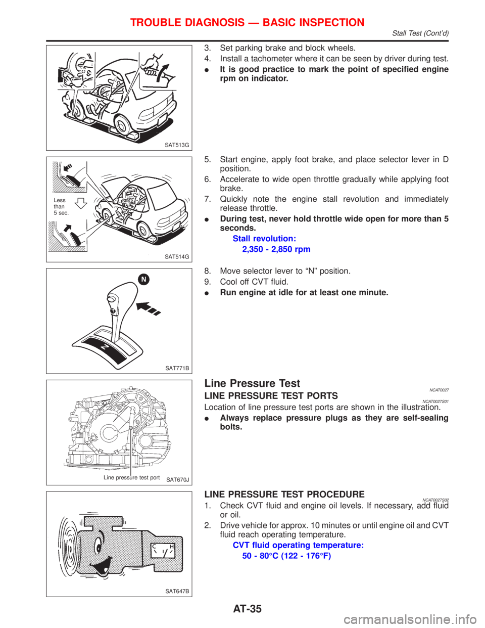
3. Set parking brake and block wheels.
4. Install a tachometer where it can be seen by driver during test.
IIt is good practice to mark the point of specified engine
rpm on indicator.
5. Start engine, apply foot brake, and place selector lever in D
position.
6. Accelerate to wide open throttle gradually while applying foot
brake.
7. Quickly note the engine stall revolution and immediately
release throttle.
IDuring test, never hold throttle wide open for more than 5
seconds.
Stall revolution:
2,350 - 2,850 rpm
8. Move selector lever to ªNº position.
9. Cool off CVT fluid.
IRun engine at idle for at least one minute.
Line Pressure TestNCAT0027LINE PRESSURE TEST PORTSNCAT0027S01Location of line pressure test ports are shown in the illustration.
IAlways replace pressure plugs as they are self-sealing
bolts.
LINE PRESSURE TEST PROCEDURENCAT0027S021. Check CVT fluid and engine oil levels. If necessary, add fluid
or oil.
2. Drive vehicle for approx. 10 minutes or until engine oil and CVT
fluid reach operating temperature.
CVT fluid operating temperature:
50 - 80ÉC (122 - 176ÉF)
SAT513G
SAT514G Less
than
5 sec.
SAT771B
SAT670J Line pressure test port
SAT647B
TROUBLE DIAGNOSIS Ð BASIC INSPECTION
Stall Test (Cont'd)
AT-35
Page 116 of 2267
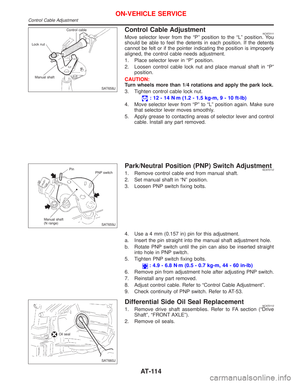
Control Cable AdjustmentNCAT0111Move selector lever from the ªPº position to the ªLº position. You
should be able to feel the detents in each position. If the detents
cannot be felt or if the pointer indicating the position is improperly
aligned, the control cable needs adjustment.
1. Place selector lever in ªPº position.
2. Loosen control cable lock nut and place manual shaft in ªPº
position.
CAUTION:
Turn wheels more than 1/4 rotations and apply the park lock.
3. Tighten control cable lock nut.
:12-14N×m (1.2 - 1.5 kg-m,9-10ft-lb)
4. Move selector lever from ªPº to ªLº position again. Make sure
that selector lever moves smoothly.
5. Apply grease to contacting areas of selector lever and control
cable. Install any part removed.
Park/Neutral Position (PNP) Switch AdjustmentNCAT01121. Remove control cable end from manual shaft.
2. Set manual shaft in ªNº position.
3. Loosen PNP switch fixing bolts.
4. Usea4mm(0.157 in) pin for this adjustment.
a. Insert the pin straight into the manual shaft adjustment hole.
b. Rotate PNP switch until the pin can also be inserted straight
into hole in PNP switch.
5. Tighten PNP switch fixing bolts.
: 4.9 - 6.8 N×m (0.5 - 0.7 kg-m, 44 - 60 in-lb)
6. Remove pin from adjustment hole after adjusting PNP switch.
7. Reinstall any part removed.
8. Adjust control cable. Refer to ªControl Cable Adjustmentº.
9. Check continuity of PNP switch. Refer to AT-53.
Differential Side Oil Seal ReplacementNCAT01131. Remove drive shaft assemblies. Refer to FA section (ªDrive
Shaftº, ªFRONT AXLEº).
2. Remove oil seals.
SAT658J Control cable
Lock nut
Manual shaft
SAT659J Pin
PNP switch
Manual shaft
(N range)
SAT660J Oil seal
ON-VEHICLE SERVICE
Control Cable Adjustment
AT-114
Page 165 of 2267
ROTOR
Rubbing Surface
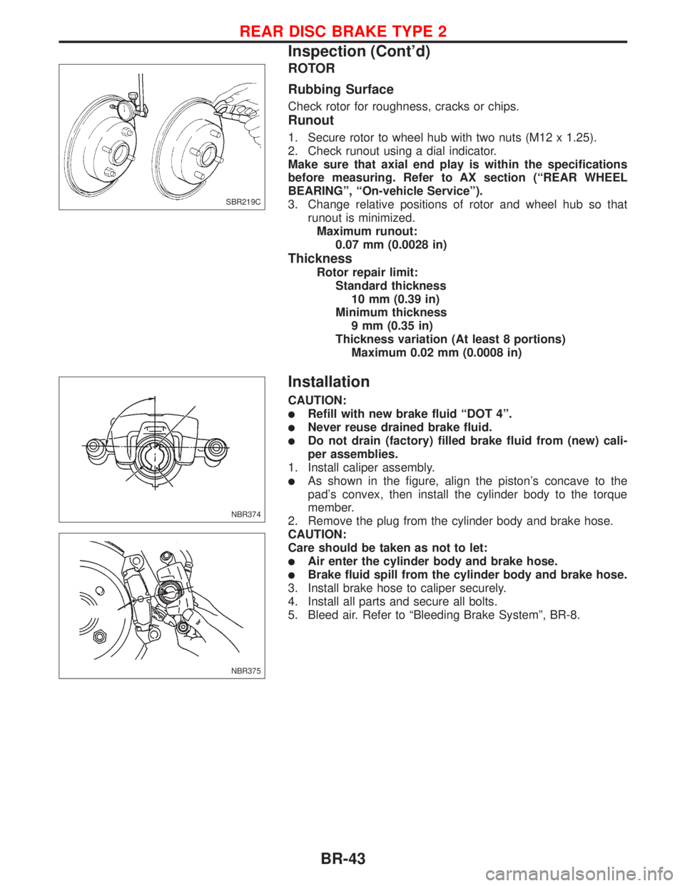
Check rotor for roughness, cracks or chips.
Runout
1. Secure rotor to wheel hub with two nuts (M12 x 1.25).
2. Check runout using a dial indicator.
Make sure that axial end play is within the specifications
before measuring. Refer to AX section (ªREAR WHEEL
BEARINGº, ªOn-vehicle Serviceº).
3. Change relative positions of rotor and wheel hub so that
runout is minimized.
Maximum runout:
0.07 mm (0.0028 in)
Thickness
Rotor repair limit:
Standard thickness
10 mm (0.39 in)
Minimum thickness
9 mm (0.35 in)
Thickness variation (At least 8 portions)
Maximum 0.02 mm (0.0008 in)
Installation
CAUTION:
lRefill with new brake fluid ªDOT 4º.
lNever reuse drained brake fluid.
lDo not drain (factory) filled brake fluid from (new) cali-
per assemblies.
1. Install caliper assembly.
lAs shown in the figure, align the piston's concave to the
pad's convex, then install the cylinder body to the torque
member.
2. Remove the plug from the cylinder body and brake hose.
CAUTION:
Care should be taken as not to let:
lAir enter the cylinder body and brake hose.
lBrake fluid spill from the cylinder body and brake hose.
3. Install brake hose to caliper securely.
4. Install all parts and secure all bolts.
5. Bleed air. Refer to ªBleeding Brake Systemº, BR-8.
SBR219C
NBR374
NBR375
REAR DISC BRAKE TYPE 2
Inspection (Cont'd)
BR-43
Page 167 of 2267
1. Release parking brake lever fully, then remove drum.
If drum is hard to remove, the following procedures
should be carried out.
a. Remove plug. To make shoe clearance, push shoe hold-
down spring to free toggle lever.
b. Install two bolts as shown. Tighten the two bolts gradu-
ally.
2. After removing retainer, remove spring by rotating shoes.
lBe careful not to damage wheel cylinder piston boots.
lBe careful not to damage parking brake cable when
separating it.
3. Remove adjuster.
4. Disconnect parking brake cable from toggle lever.
5. Remove retainer ring with a suitable tool. Then separate
toggle lever and brake shoe.
Inspection Ð Wheel Cylinder
lCheck wheel cylinder for leakage.
lCheck for wear, damage and loose conditions. Replace if any
such condition exists.
SBR617E
SBR020A
SBR214B
SBR329C
SBR330C
REAR DRUM BRAKE
Removal (Cont'd)
BR-45
Page 229 of 2267
CAUTION:
lDisconnect both battery cables in advance.
lDisconnect air bag system line in advance.
lNever tamper with or force air bag lid open, as this may adversely affect air bag performance.
lBe careful not to scratch pad and other parts.
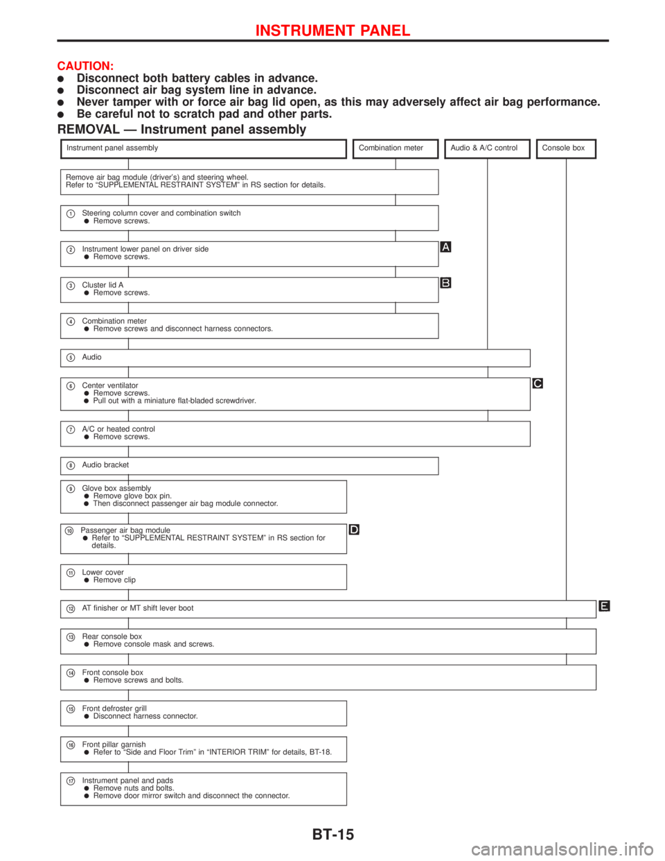
REMOVAL Ð Instrument panel assembly
Instrument panel assemblyCombination meterAudio & A/C controlConsole box
Remove air bag module (driver's) and steering wheel.
Refer to ªSUPPLEMENTAL RESTRAINT SYSTEMº in RS section for details.
p1Steering column cover and combination switchlRemove screws.
p2Instrument lower panel on driver sidelRemove screws.
p3Cluster lid AlRemove screws.
p4Combination meterlRemove screws and disconnect harness connectors.
p5Audio
p6Center ventilatorlRemove screws.lPull out with a miniature flat-bladed screwdriver.
p7A/C or heated controllRemove screws.
p8Audio bracket
p9Glove box assemblylRemove glove box pin.lThen disconnect passenger air bag module connector.
p10Passenger air bag modulelRefer to ªSUPPLEMENTAL RESTRAINT SYSTEMº in RS section for
details.
p11Lower coverlRemove clip
p12AT finisher or MT shift lever boot
p13Rear console boxlRemove console mask and screws.
p14Front console boxlRemove screws and bolts.
p15Front defroster grilllDisconnect harness connector.
p16Front pillar garnishlRefer to ªSide and Floor Trimº in ªINTERIOR TRIMº for details, BT-18.
p17Instrument panel and padslRemove nuts and bolts.lRemove door mirror switch and disconnect the connector.
INSTRUMENT PANEL
BT-15
Page 292 of 2267
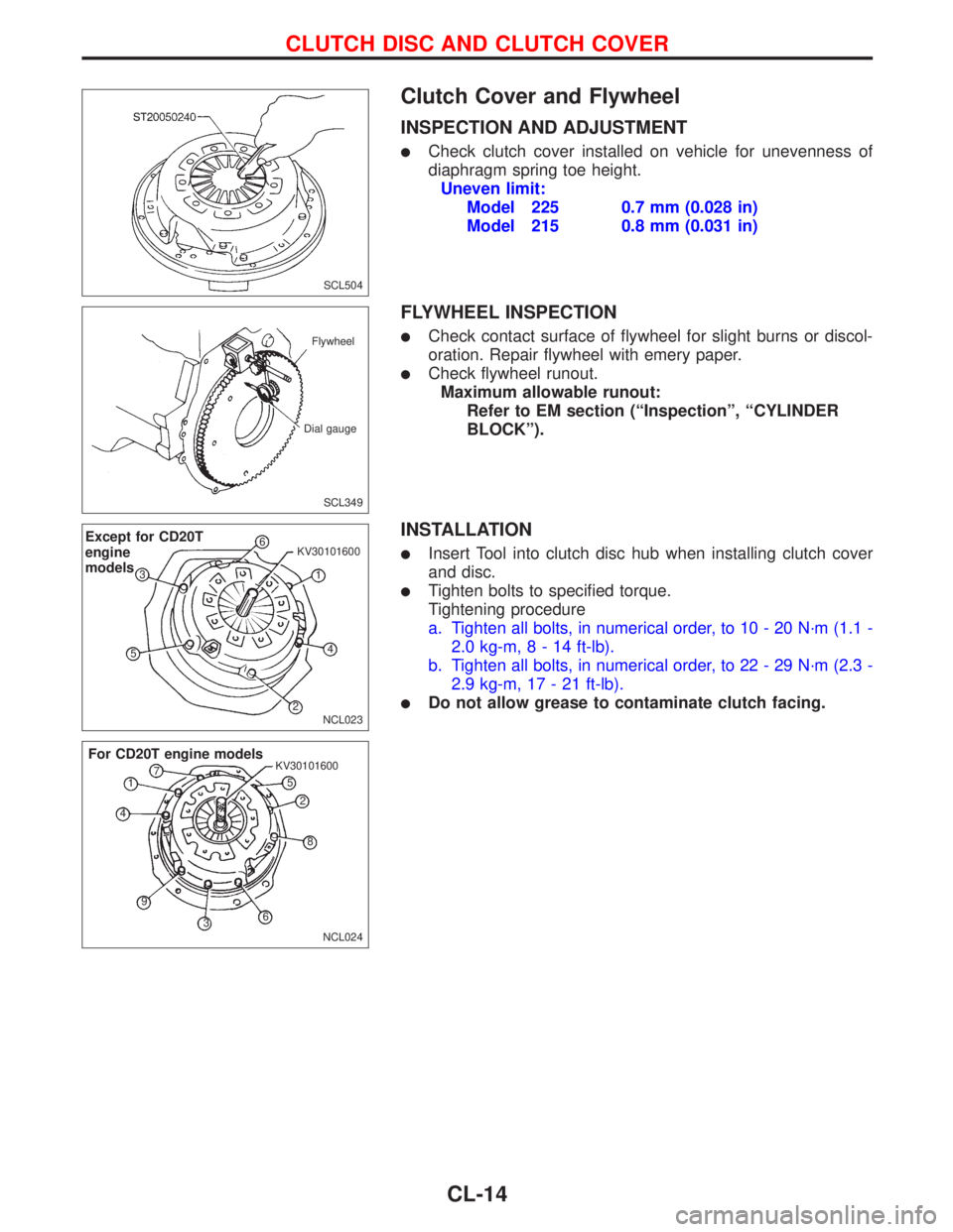
Clutch Cover and Flywheel
INSPECTION AND ADJUSTMENT
lCheck clutch cover installed on vehicle for unevenness of
diaphragm spring toe height.
Uneven limit:
Model 225 0.7 mm (0.028 in)
Model 215 0.8 mm (0.031 in)
FLYWHEEL INSPECTION
lCheck contact surface of flywheel for slight burns or discol-
oration. Repair flywheel with emery paper.
lCheck flywheel runout.
Maximum allowable runout:
Refer to EM section (ªInspectionº, ªCYLINDER
BLOCKº).
INSTALLATION
lInsert Tool into clutch disc hub when installing clutch cover
and disc.
lTighten bolts to specified torque.
Tightening procedure
a. Tighten all bolts, in numerical order, to 10 - 20 N´m (1.1 -
2.0 kg-m,8-14ft-lb).
b. Tighten all bolts, in numerical order, to 22 - 29 N´m (2.3 -
2.9 kg-m, 17 - 21 ft-lb).
lDo not allow grease to contaminate clutch facing.
SCL504
SCL349 Flywheel
Dial gauge
NCL023
Except for CD20T
engine
models6
1 KV30101600
4
2 53
NCL024 KV30101600
For CD20T engine models
1
2
3 45
6 7
8
9
CLUTCH DISC AND CLUTCH COVER
CL-14
Page 1560 of 2267
CAUTION:
IAfter removing timing chain, do not turn crankshaft and
camshaft separately, or valves will strike piston heads.
IWhen installing chain tensioner, oil seals, or other sliding
parts, lubricate contacting surfaces with new engine oil.
IApply new engine oil to bolt threads and seat surfaces
when installing camshaft sprocket and crankshaft pulley.
IWhen removing oil pump assembly, remove camshaft
position sensor (PHASE), then remove timing chain from
engine.
IBe careful not to damage sensor edges.
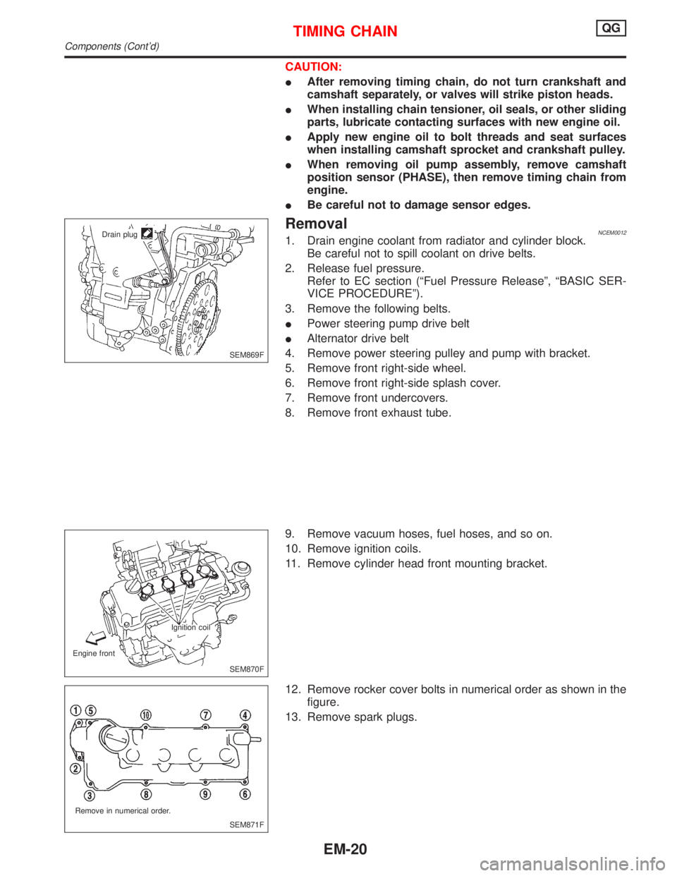
RemovalNCEM00121. Drain engine coolant from radiator and cylinder block.
Be careful not to spill coolant on drive belts.
2. Release fuel pressure.
Refer to EC section (ªFuel Pressure Releaseº, ªBASIC SER-
VICE PROCEDUREº).
3. Remove the following belts.
IPower steering pump drive belt
IAlternator drive belt
4. Remove power steering pulley and pump with bracket.
5. Remove front right-side wheel.
6. Remove front right-side splash cover.
7. Remove front undercovers.
8. Remove front exhaust tube.
9. Remove vacuum hoses, fuel hoses, and so on.
10. Remove ignition coils.
11. Remove cylinder head front mounting bracket.
12. Remove rocker cover bolts in numerical order as shown in the
figure.
13. Remove spark plugs.
SEM869F Drain plug
SEM870F Ignition coil
Engine front
SEM871F Remove in numerical order.
TIMING CHAINQG
Components (Cont'd)
EM-20
Page 1568 of 2267
27. Install rocker cover and tighten bolts in numerical order as
shown in the figure.
28. Install spark plugs.
29. Install ignition coils.
30. Install engine front mounting.
31. Install front exhaust tube.
32. Install front undercover.
33. Install front right splash cover.
34. Install front right wheel.
35. Install power steering pulley and pump with bracket.
To check power steering fluid, refer to MA section (ªChecking
Power Steering Fluid and Linesº, ªCHASSIS AND BODY
MAINTENANCEº).
36. Drive belts.
For adjusting drive belt deflection, refer to MA section (ªCheck-
ing Drive Beltsº, ªENGINE MAINTENANCEº).
37. Reinstall parts in reverse order of removal.
SEM908F Tighten in numerical order
TIMING CHAINQG
Installation (Cont'd)
EM-28