1999 NISSAN PRIMERA air conditioning
[x] Cancel search: air conditioningPage 295 of 2267
ENGINE CONTROL SYSTEM
SECTION
EC
CONTENTS
CD20T
PRECAUTIONS AND PREPARATION.......................... 3
Special Service Tools ................................................ 3
Engine Fuel & Emission Control System .................. 5
Supplemental Restraint System (SRS)²AIR
BAG²and²SEAT BELT PRE-TENSIONER²............. 6
Precautions for On Board Diagnostic (OBD)
System of Engine ...................................................... 6
Precautions ................................................................ 7
ENGINE AND EMISSION CONTROL OVERALL
SYSTEM......................................................................... 9
Engine Control Module Component Parts
Location ..................................................................... 9
Circuit Diagram ......................................................... 11
System Diagram ...................................................... 12
Vacuum Hose Drawing ............................................ 13
System Chart ........................................................... 14
ENGINE AND EMISSION BASIC CONTROL
SYSTEM DESCRIPTION............................................. 15
Glow Control System ............................................... 15
Fuel Injection System .............................................. 15
Fuel Injection Timing System .................................. 18
Air Conditioning Cut Control .................................... 20
Cooling Fan Control................................................. 20
CRANKCASE VENTILATION SYSTEM...................... 21
Description ............................................................... 21
Blow-by Control Valve ............................................. 21
Ventilation Hose ....................................................... 21
INJECTION NOZZLE................................................... 22
Removal and Installation ......................................... 22
Test and Adjustment ................................................ 22
ELECTRONIC FUEL INJECTION PUMP.................... 24
Removal ................................................................... 24
Installation ................................................................ 25Disassembly and Assembly ..................................... 26
ON BOARD DIAGNOSTIC SYSTEM
DESCRIPTION............................................................. 27
CONSULT-II ............................................................. 27
TROUBLE DIAGNOSIS - INTRODUCTION................ 33
Introduction .............................................................. 33
Diagnostic Worksheet .............................................. 34
TROUBLE DIAGNOSIS - WORK FLOW.................... 35
Work Flow ................................................................ 35
Description for Work Flow ....................................... 36
TROUBLE DIAGNOSIS - BASIC INSPECTION......... 37
Basic Inspection....................................................... 37
TROUBLE DIAGNOSIS - GENERAL
DESCRIPTION............................................................. 39
Diagnostic Trouble Chart ......................................... 39
Symptom Matrix Chart ............................................. 47
CONSULT-II Reference Value in Data Monitor
Mode ........................................................................ 50
Major Sensor Reference Graph in Data Monitor
Mode ........................................................................ 51
ECM Terminals and Reference Value ..................... 52
TROUBLE DIAGNOSIS FOR POWER SUPPLY........ 59
Main Power Supply and Ground Circuit .................. 59
TROUBLE DIAGNOSIS 1............................................ 62
Mass Air Flow Sensor (MAFS) ................................ 62
TROUBLE DIAGNOSIS 2............................................ 66
Engine Coolant Temperature (ECT) Sensor ........... 66
TROUBLE DIAGNOSIS 3............................................ 70
Vehicle Speed Sensor (VSS) .................................. 70
TROUBLE DIAGNOSIS 4............................................ 74
Control Sleeve Position Sensor (CSPS) ................. 74
TROUBLE DIAGNOSIS 5............................................ 78
Electric Governor ..................................................... 78
TROUBLE DIAGNOSIS 6............................................ 82
EC
Page 308 of 2267
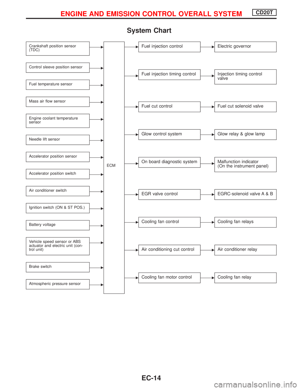
System Chart
Crankshaft position sensor
(TDC)E
ECM
Control sleeve position sensorE
Fuel temperature sensorE
Mass air flow sensorE
Engine coolant temperature
sensorE
Needle lift sensorE
Accelerator position sensorE
Accelerator position switchE
Air conditioner switchE
Ignition switch (ON & ST POS.)E
Battery voltageE
Vehicle speed sensor or ABS
actuator and electric unit (con-
trol unit)E
Brake switchE
Atmospheric pressure sensorE
EFuel injection controlEElectric governor
EFuel injection timing controlEInjection timing control
valve
EFuel cut controlEFuel cut solenoid valve
EGlow control systemEGlow relay & glow lamp
EOn board diagnostic systemEMalfunction indicator
(On the instrument panel)
EEGR valve controlEEGRC-solenoid valve A & B
ECooling fan controlECooling fan relays
EAir conditioning cut controlEAir conditioner relay
ECooling fan motor controlECooling fan relay
ENGINE AND EMISSION CONTROL OVERALL SYSTEMCD20T
EC-14
Page 314 of 2267
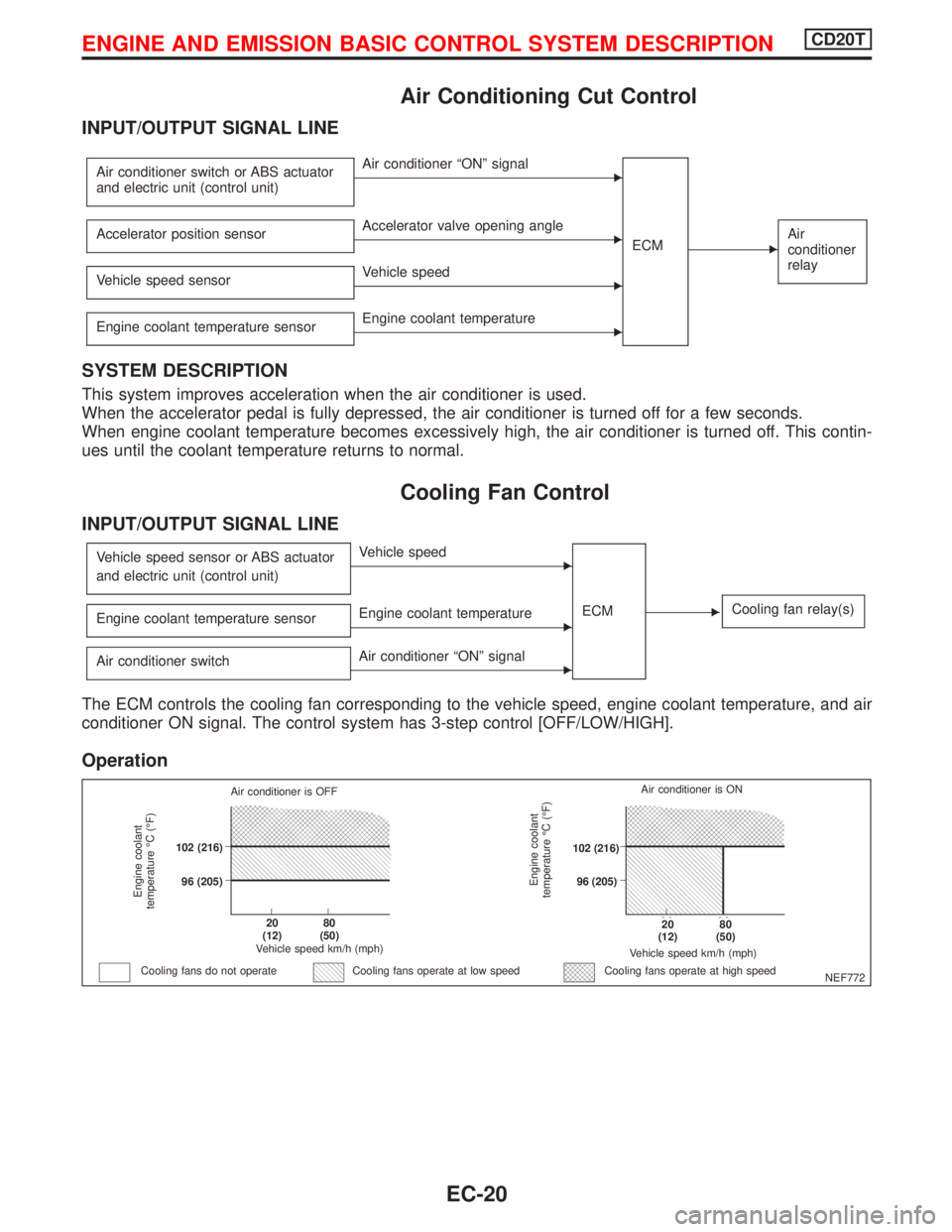
Air Conditioning Cut Control
INPUT/OUTPUT SIGNAL LINE
Air conditioner switch or ABS actuator
and electric unit (control unit)EAir conditioner ªONº signal
ECM
EAir
conditioner
relayAccelerator position sensorEAccelerator valve opening angle
Vehicle speed sensor
EVehicle speed
Engine coolant temperature sensor
EEngine coolant temperature
SYSTEM DESCRIPTION
This system improves acceleration when the air conditioner is used.
When the accelerator pedal is fully depressed, the air conditioner is turned off for a few seconds.
When engine coolant temperature becomes excessively high, the air conditioner is turned off. This contin-
ues until the coolant temperature returns to normal.
Cooling Fan Control
INPUT/OUTPUT SIGNAL LINE
Vehicle speed sensor or ABS actuator
and electric unit (control unit)EVehicle speed
ECM
ECooling fan relay(s)Engine coolant temperature sensorEEngine coolant temperature
Air conditioner switch
EAir conditioner ªONº signal
The ECM controls the cooling fan corresponding to the vehicle speed, engine coolant temperature, and air
conditioner ON signal. The control system has 3-step control [OFF/LOW/HIGH].
Operation
NEF772
Engine coolant
temperature ÉC (ÉF)
Air conditioner is OFF
.102 (216)
.96 (205)
.20
(12).80
(50)
Vehicle speed km/h (mph)
Cooling fans do not operateCooling fans operate at high speed
Engine coolant
temperature ÉC (ÉF)
Vehicle speed km/h (mph)
.20
(12).80
(50)
.102 (216)
.96 (205)Air conditioner is ON
Cooling fans operate at low speed
ENGINE AND EMISSION BASIC CONTROL SYSTEM DESCRIPTIONCD20T
EC-20
Page 443 of 2267
ENGINE CONTROL SYSTEM
SECTION
EC
CONTENTS
QG16I18DE
TROUBLE DIAGNOSIS - INDEX....................................6
Alphabetical & P No. Index for DTC ...........................6
PRECAUTIONS...............................................................9
Supplemental Restraint System (SRS)²AIR
BAG²and²SEAT BELT PRE-TENSIONER²...............9
Precautions for On Board Diagnostic (OBD)
System of Engine ........................................................9
Engine Fuel & Emission Control System ..................10
Precautions ................................................................ 11
Wiring Diagrams and Trouble Diagnosis ...................12
PREPARATION..............................................................13
Special Service Tools ................................................13
Commercial Service Tool ...........................................13
ENGINE AND EMISSION CONTROL OVERALL
SYSTEM.........................................................................14
Engine Control Component Parts Location ...............14
Circuit Diagram ..........................................................17
System Diagram ........................................................18
Vacuum Hose Drawing ..............................................19
System Chart .............................................................20
ENGINE AND EMISSION BASIC CONTROL
SYSTEM DESCRIPTION...............................................21
Multiport Fuel Injection (MFI) System .......................21
Electronic Ignition (EI) System ..................................23
Air Conditioning Cut Control ......................................24
Fuel Cut Control (at no load & high engine
speed) ........................................................................25
Evaporative Emission System ...................................25
Positive Crankcase Ventilation ..................................28
BASIC SERVICE PROCEDURE...................................29
Fuel Pressure Release ..............................................29
Fuel Pressure Check .................................................29
Fuel Pressure Regulator Check ................................30
Injector .......................................................................30
Idle Speed/Ignition Timing/Idle Mixture Ratio
Adjustment .................................................................32Idle Air Volume Learning ...........................................33
ON BOARD DIAGNOSTIC SYSTEM
DESCRIPTION...............................................................36
Introduction ................................................................36
Two Trip Detection Logic ...........................................36
Emission-related Diagnostic Information ...................37
Malfunction Indicator (MI) ..........................................45
OBD System Operation Chart ...................................50
CONSULT-II ...............................................................55
Generic Scan Tool (GST) ..........................................66
TROUBLE DIAGNOSIS - INTRODUCTION..................68
Introduction ................................................................68
Work Flow ..................................................................70
TROUBLE DIAGNOSIS - BASIC INSPECTION...........72
Basic Inspection.........................................................72
TROUBLE DIAGNOSIS - GENERAL
DESCRIPTION...............................................................80
DTC Inspection Priority Chart....................................80
Fail-safe Chart ...........................................................81
Symptom Matrix Chart ...............................................82
CONSULT-II Reference Value in Data Monitor
Mode ..........................................................................86
Major Sensor Reference Graph in Data Monitor
Mode ..........................................................................88
ECM Terminals and Reference Value .......................91
TROUBLE DIAGNOSIS - SPECIFICATION VALUE....98
Description .................................................................98
Testing Condition .......................................................98
Inspection Procedure .................................................98
Diagnostic Procedure ................................................99
TROUBLE DIAGNOSIS FOR INTERMITTENT
INCIDENT.....................................................................102
Description ...............................................................102
Diagnostic Procedure ..............................................102
TROUBLE DIAGNOSIS FOR POWER SUPPLY........103
Main Power Supply and Ground Circuit ..................103
EC
Page 462 of 2267
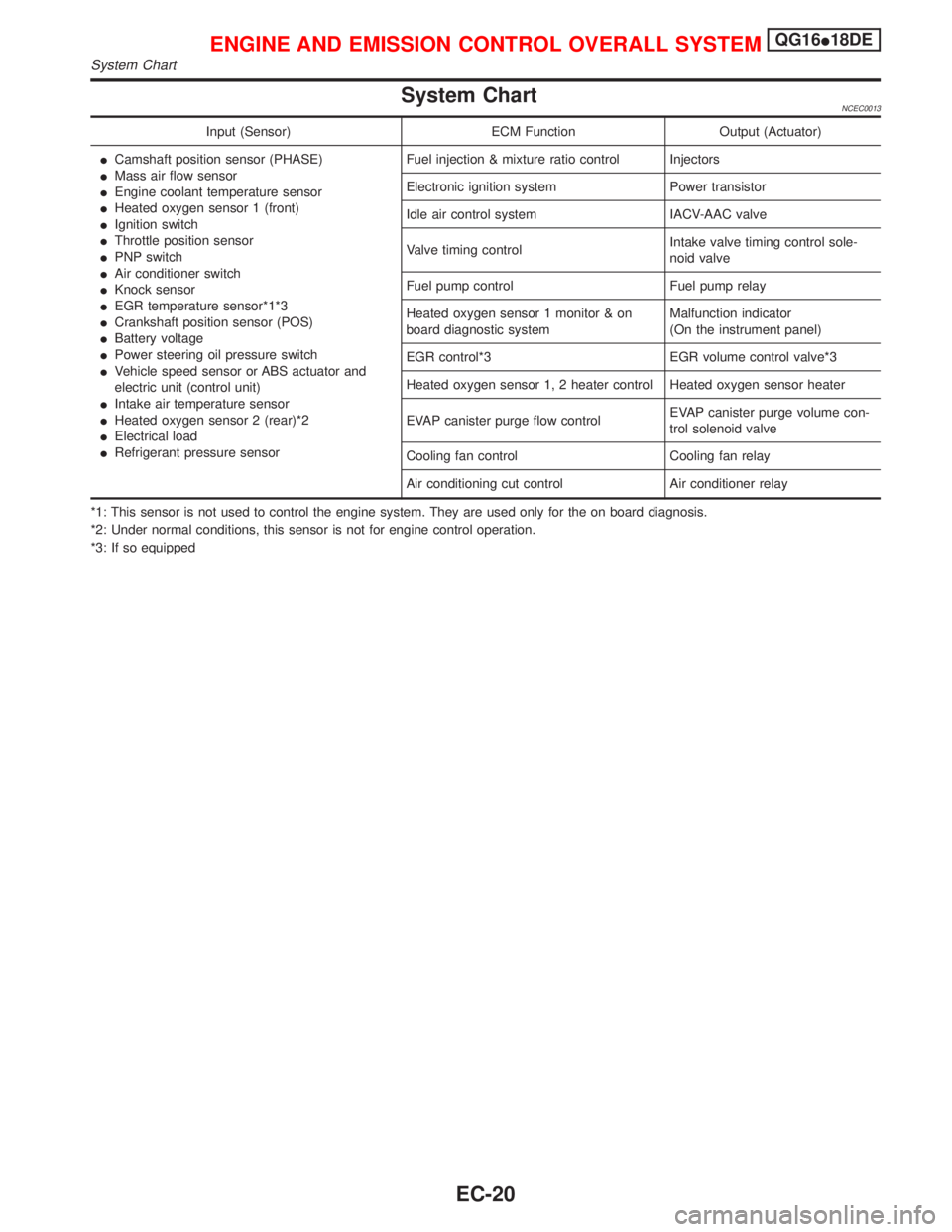
System ChartNCEC0013
Input (Sensor) ECM Function Output (Actuator)
ICamshaft position sensor (PHASE)
IMass air flow sensor
IEngine coolant temperature sensor
IHeated oxygen sensor 1 (front)
IIgnition switch
IThrottle position sensor
IPNP switch
IAir conditioner switch
IKnock sensor
IEGR temperature sensor*1*3
ICrankshaft position sensor (POS)
IBattery voltage
IPower steering oil pressure switch
IVehicle speed sensor or ABS actuator and
electric unit (control unit)
IIntake air temperature sensor
IHeated oxygen sensor 2 (rear)*2
IElectrical load
IRefrigerant pressure sensorFuel injection & mixture ratio control Injectors
Electronic ignition system Power transistor
Idle air control system IACV-AAC valve
Valve timing controlIntake valve timing control sole-
noid valve
Fuel pump control Fuel pump relay
Heated oxygen sensor 1 monitor & on
board diagnostic systemMalfunction indicator
(On the instrument panel)
EGR control*3 EGR volume control valve*3
Heated oxygen sensor 1, 2 heater control Heated oxygen sensor heater
EVAP canister purge flow controlEVAP canister purge volume con-
trol solenoid valve
Cooling fan control Cooling fan relay
Air conditioning cut control Air conditioner relay
*1: This sensor is not used to control the engine system. They are used only for the on board diagnosis.
*2: Under normal conditions, this sensor is not for engine control operation.
*3: If so equipped
ENGINE AND EMISSION CONTROL OVERALL SYSTEMQG16I18DE
System Chart
EC-20
Page 466 of 2267
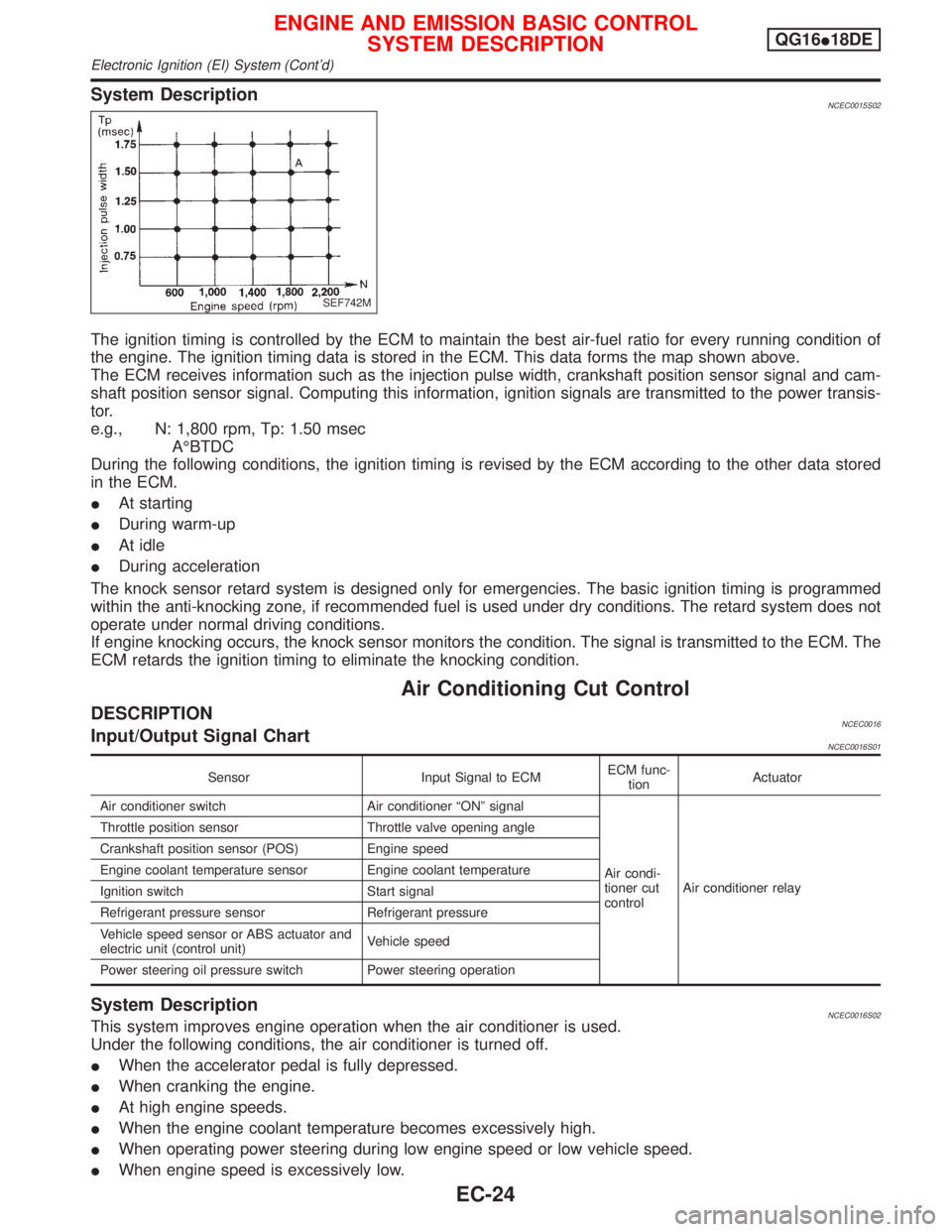
System DescriptionNCEC0015S02
The ignition timing is controlled by the ECM to maintain the best air-fuel ratio for every running condition of
the engine. The ignition timing data is stored in the ECM. This data forms the map shown above.
The ECM receives information such as the injection pulse width, crankshaft position sensor signal and cam-
shaft position sensor signal. Computing this information, ignition signals are transmitted to the power transis-
tor.
e.g., N: 1,800 rpm, Tp: 1.50 msec
AÉBTDC
During the following conditions, the ignition timing is revised by the ECM according to the other data stored
in the ECM.
IAt starting
IDuring warm-up
IAt idle
IDuring acceleration
The knock sensor retard system is designed only for emergencies. The basic ignition timing is programmed
within the anti-knocking zone, if recommended fuel is used under dry conditions. The retard system does not
operate under normal driving conditions.
If engine knocking occurs, the knock sensor monitors the condition. The signal is transmitted to the ECM. The
ECM retards the ignition timing to eliminate the knocking condition.
Air Conditioning Cut Control
DESCRIPTIONNCEC0016Input/Output Signal ChartNCEC0016S01
Sensor Input Signal to ECMECM func-
tionActuator
Air conditioner switch Air conditioner ªONº signal
Air condi-
tioner cut
controlAir conditioner relay Throttle position sensor Throttle valve opening angle
Crankshaft position sensor (POS) Engine speed
Engine coolant temperature sensor Engine coolant temperature
Ignition switch Start signal
Refrigerant pressure sensor Refrigerant pressure
Vehicle speed sensor or ABS actuator and
electric unit (control unit)Vehicle speed
Power steering oil pressure switch Power steering operation
System DescriptionNCEC0016S02This system improves engine operation when the air conditioner is used.
Under the following conditions, the air conditioner is turned off.
IWhen the accelerator pedal is fully depressed.
IWhen cranking the engine.
IAt high engine speeds.
IWhen the engine coolant temperature becomes excessively high.
IWhen operating power steering during low engine speed or low vehicle speed.
IWhen engine speed is excessively low.
SEF742M
ENGINE AND EMISSION BASIC CONTROL
SYSTEM DESCRIPTIONQG16I18DE
Electronic Ignition (EI) System (Cont'd)
EC-24
Page 475 of 2267
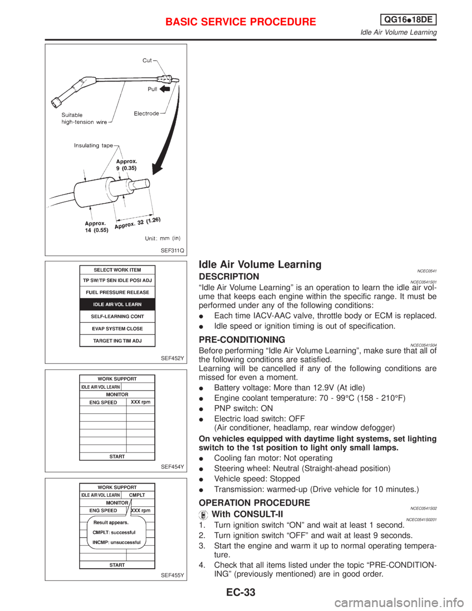
Idle Air Volume LearningNCEC0541DESCRIPTIONNCEC0541S01ªIdle Air Volume Learningº is an operation to learn the idle air vol-
ume that keeps each engine within the specific range. It must be
performed under any of the following conditions:
IEach time IACV-AAC valve, throttle body or ECM is replaced.
IIdle speed or ignition timing is out of specification.
PRE-CONDITIONINGNCEC0541S04Before performing ªIdle Air Volume Learningº, make sure that all of
the following conditions are satisfied.
Learning will be cancelled if any of the following conditions are
missed for even a moment.
IBattery voltage: More than 12.9V (At idle)
IEngine coolant temperature: 70 - 99ÉC (158 - 210ÉF)
IPNP switch: ON
IElectric load switch: OFF
(Air conditioner, headlamp, rear window defogger)
On vehicles equipped with daytime light systems, set lighting
switch to the 1st position to light only small lamps.
ICooling fan motor: Not operating
ISteering wheel: Neutral (Straight-ahead position)
IVehicle speed: Stopped
ITransmission: warmed-up (Drive vehicle for 10 minutes.)
OPERATION PROCEDURENCEC0541S02With CONSULT-IINCEC0541S02011. Turn ignition switch ªONº and wait at least 1 second.
2. Turn ignition switch ªOFFº and wait at least 9 seconds.
3. Start the engine and warm it up to normal operating tempera-
ture.
4. Check that all items listed under the topic ªPRE-CONDITION-
INGº (previously mentioned) are in good order.
SEF311Q
SEF452Y
SEF454Y
SEF455Y
BASIC SERVICE PROCEDUREQG16I18DE
Idle Air Volume Learning
EC-33
Page 801 of 2267
ENGINE CONTROL SYSTEM
SECTION
EC
CONTENTS
SR20DE
TROUBLE DIAGNOSIS - INDEX....................................6
Alphabetical & P No. Index for DTC ...........................6
PRECAUTIONS.............................................................10
Supplemental Restraint System (SRS)²AIR
BAG²and²SEAT BELT PRE-TENSIONER².............10
Precautions for On Board Diagnostic (OBD)
System of Engine and CVT .......................................10
Engine Fuel & Emission Control System .................. 11
Precautions ................................................................12
Wiring Diagrams and Trouble Diagnosis ...................13
PREPARATION.............................................................14
Special Service Tools ................................................14
Commercial Service Tool ...........................................14
ENGINE AND EMISSION CONTROL OVERALL
SYSTEM.........................................................................15
Engine Control Component Parts Location ...............15
Circuit Diagram ..........................................................19
System Diagram ........................................................20
Vacuum Hose Drawing ..............................................21
System Chart .............................................................22
ENGINE AND EMISSION BASIC CONTROL
SYSTEM DESCRIPTION...............................................23
Multiport Fuel Injection (MFI) System .......................23
Distributor Ignition (DI) System .................................25
Air Conditioning Cut Control ......................................26
Fuel Cut Control (at no load & high engine
speed) ........................................................................27
Evaporative Emission System ...................................27
Positive Crankcase Ventilation ..................................30
BASIC SERVICE PROCEDURE...................................31
Fuel Pressure Release ..............................................31
Fuel Pressure Check .................................................31
Fuel Pressure Regulator Check ................................32
Injector .......................................................................32
Idle Speed/Ignition Timing/Idle Mixture Ratio
Adjustment .................................................................34Idle Air Volume Learning ...........................................46
ON BOARD DIAGNOSTIC SYSTEM
DESCRIPTION...............................................................48
Introduction ................................................................48
Two Trip Detection Logic ...........................................48
Emission-related Diagnostic Information ...................49
Malfunction Indicator (MI) ..........................................58
OBD System Operation Chart ...................................63
CONSULT-II ...............................................................68
Generic Scan Tool (GST) ..........................................78
TROUBLE DIAGNOSIS - INTRODUCTION..................80
Introduction ................................................................80
Work Flow ..................................................................82
TROUBLE DIAGNOSIS - BASIC INSPECTION...........84
Basic Inspection.........................................................84
TROUBLE DIAGNOSIS - GENERAL
DESCRIPTION...............................................................92
DTC Inspection Priority Chart....................................92
Fail-safe Chart ...........................................................93
Symptom Matrix Chart ...............................................94
CONSULT-II Reference Value in Data Monitor
Mode ..........................................................................98
Major Sensor Reference Graph in Data Monitor
Mode ........................................................................100
ECM Terminals and Reference Value .....................103
TROUBLE DIAGNOSIS - SPECIFICATION VALUE.. 110
Description ............................................................... 110
Testing Condition ..................................................... 110
Inspection Procedure ............................................... 110
Diagnostic Procedure .............................................. 111
TROUBLE DIAGNOSIS FOR INTERMITTENT
INCIDENT..................................................................... 114
Description ............................................................... 114
Diagnostic Procedure .............................................. 114
TROUBLE DIAGNOSIS FOR POWER SUPPLY........ 115
Main Power Supply and Ground Circuit .................. 115
EC