1999 NISSAN PRIMERA fuel filter location
[x] Cancel search: fuel filter locationPage 471 of 2267

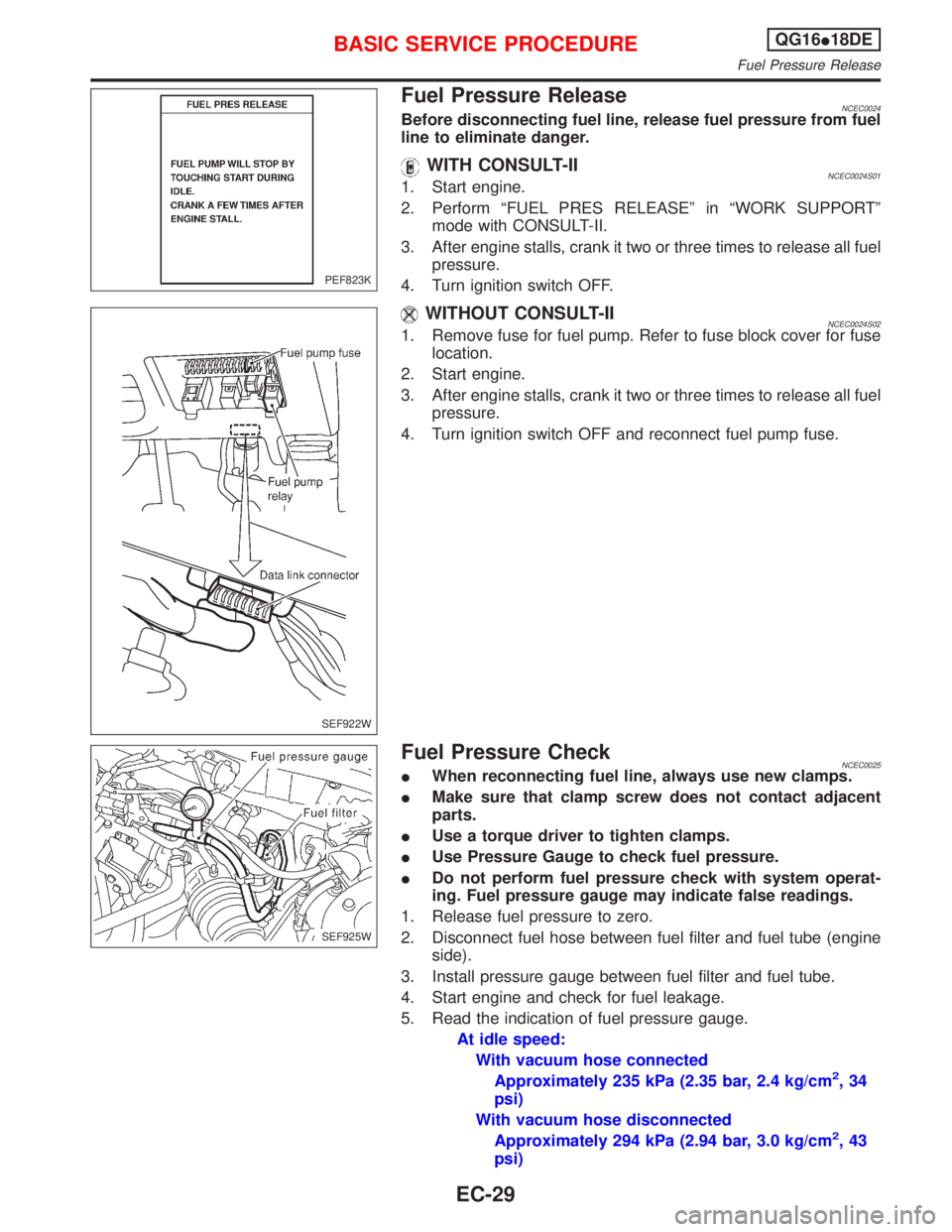
Fuel Pressure ReleaseNCEC0024Before disconnecting fuel line, release fuel pressure from fuel
line to eliminate danger.
WITH CONSULT-IINCEC0024S011. Start engine.
2. Perform ªFUEL PRES RELEASEº in ªWORK SUPPORTº
mode with CONSULT-II.
3. After engine stalls, crank it two or three times to release all fuel
pressure.
4. Turn ignition switch OFF.
WITHOUT CONSULT-IINCEC0024S021. Remove fuse for fuel pump. Refer to fuse block cover for fuse
location.
2. Start engine.
3. After engine stalls, crank it two or three times to release all fuel
pressure.
4. Turn ignition switch OFF and reconnect fuel pump fuse.
Fuel Pressure CheckNCEC0025IWhen reconnecting fuel line, always use new clamps.
IMake sure that clamp screw does not contact adjacent
parts.
IUse a torque driver to tighten clamps.
IUse Pressure Gauge to check fuel pressure.
IDo not perform fuel pressure check with system operat-
ing. Fuel pressure gauge may indicate false readings.
1. Release fuel pressure to zero.
2. Disconnect fuel hose between fuel filter and fuel tube (engine
side).
3. Install pressure gauge between fuel filter and fuel tube.
4. Start engine and check for fuel leakage.
5. Read the indication of fuel pressure gauge.
At idle speed:
With vacuum hose connected
Approximately 235 kPa (2.35 bar, 2.4 kg/cm
2,34
psi)
With vacuum hose disconnected
Approximately 294 kPa (2.94 bar, 3.0 kg/cm
2,43
psi)
PEF823K
SEF922W
SEF925W
BASIC SERVICE PROCEDUREQG16I18DE
Fuel Pressure Release
EC-29
Page 831 of 2267

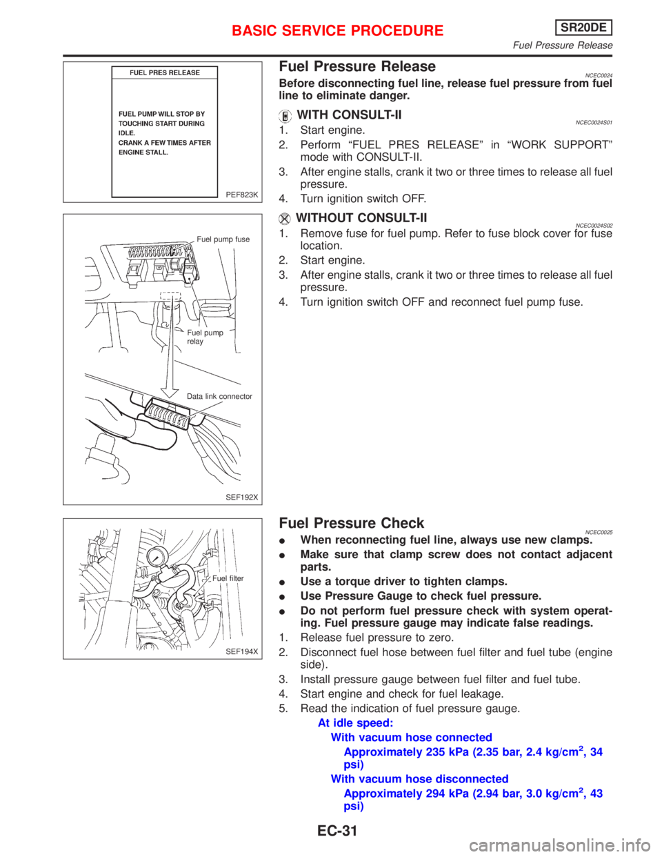
Fuel Pressure ReleaseNCEC0024Before disconnecting fuel line, release fuel pressure from fuel
line to eliminate danger.
WITH CONSULT-IINCEC0024S011. Start engine.
2. Perform ªFUEL PRES RELEASEº in ªWORK SUPPORTº
mode with CONSULT-II.
3. After engine stalls, crank it two or three times to release all fuel
pressure.
4. Turn ignition switch OFF.
WITHOUT CONSULT-IINCEC0024S021. Remove fuse for fuel pump. Refer to fuse block cover for fuse
location.
2. Start engine.
3. After engine stalls, crank it two or three times to release all fuel
pressure.
4. Turn ignition switch OFF and reconnect fuel pump fuse.
Fuel Pressure CheckNCEC0025IWhen reconnecting fuel line, always use new clamps.
IMake sure that clamp screw does not contact adjacent
parts.
IUse a torque driver to tighten clamps.
IUse Pressure Gauge to check fuel pressure.
IDo not perform fuel pressure check with system operat-
ing. Fuel pressure gauge may indicate false readings.
1. Release fuel pressure to zero.
2. Disconnect fuel hose between fuel filter and fuel tube (engine
side).
3. Install pressure gauge between fuel filter and fuel tube.
4. Start engine and check for fuel leakage.
5. Read the indication of fuel pressure gauge.
At idle speed:
With vacuum hose connected
Approximately 235 kPa (2.35 bar, 2.4 kg/cm
2,34
psi)
With vacuum hose disconnected
Approximately 294 kPa (2.94 bar, 3.0 kg/cm
2,43
psi)
PEF823K
Fuel pump fuse
Fuel pump
relay
Data link connector
SEF192X
Fuel filter
SEF194X
BASIC SERVICE PROCEDURESR20DE
Fuel Pressure Release
EC-31
Page 1970 of 2267

Combination meter removal and instal-
lation - See Instrument panel ......................BT-15
Combination switch .........................................EL-64
Combustion chamber replacement ..............EM-146
Component location (cool box) ......................HA-39
Compression pressure ..........EM-69, 126, 188, 196
Compressor clutch removal and
installation .................................................HA-111
Compressor mounting ..................................HA-109
Compressor precaution ....................................HA-7
Compressor special service tool ......................HA-7
Connecting rod......EM-55, 171, 176, 186, 193, 200
Connecting rod bearing
clearance....EM-58, 111, 115, 170, 187, 195, 201
Connecting rod bushing clearance ........EM-59, 116
Console box - See Instrument panel ..............BT-15
CONSULT for ABS .........................................BR-69
CONSULT for engine ...........EC-QG-55, EC-SR-68,
EC-CD-27
CONSULT-II general information .....................GI-39
Control sleeve position sensor ................EC-CD-74
Converter housing installation .......................AT-117
COOL/F - Wiring diagram ....................EC-QG-292,
EC-SR-282, EC-CD-89
Coolant replacement .........................MA-19, 29, 40
Cooling circuit (engine) ........................LC-8, 21, 31
Cooling fan control ...........EC-QG-289, EC-SR-279,
EC-CD-20, 87
Cooling fan motor .............EC-QG-299, EC-SR-289
Cooling fan relay ..............EC-QG-299, EC-SR-289,
EC-CD-96
Crank angle sensor built into distributor
- See Camshaft position sensor .......EC-QG-238,
EC-SR-239
‘‘Crankcase emission control system -
See positive crankcase
ventilation’’ .........................EC-QG-28, EC-SR-30
Crankcase ventilation system - See
Positive crankcase
ventilation ..........................EC-QG-28, EC-SR-30
Crankshaft ........EM-53, 57, 61, 110, 113, 118, 131,
138, 139, 167, 172, 175, 186, 194, 200
Crankshaft position sensor (OBD) .......EC-QG-232,
EC-SR-234, 290
Crankshaft position sensor (POS).........EC-QG-232
Crankshaft position sensor (TDC)..........EC-CD-114
CSPS - Wiring diagram ...........................EC-CD-75
Cylinder block .........................EM-52, 55, 109, 166,
173, 184, 192, 199
Cylinder head ..........EM-31, 86, 140, 178, 188, 196
D
Data link connector for
Consult ..............................EC-QG-29, EC-SR-31
Daytime light system.......................................EL-78
DEF - Wiring diagram ...................................EL-209
Detonation sensor - See Knock
sensor ............................EC-QG-228, EC-SR-230
Diagnosis sensor unit .....................................RS-13Diagnostic trouble code (DTC) for OBD
system ...................................EC-QG-6, EC-SR-6
Diagnostic trouble code (DTC) inspec-
tion priority chart...............EC-QG-80, EC-SR-92,
EC-CD-39
Dimensions ......................................................GI-45
Direct ignition system ..............................EC-QG-32
Door lock .........................................................BT-13
Door mirror ......................................................BT-58
Door trim .........................................................BT-24
Door, front .......................................................BT-13
Door, rear ........................................................BT-13
Drive belt inspection ..........................MA-18, 28, 39
Drive plate runout...................................EM-60, 117
Drive shaft (front) ............................................FA-15
Dropping resistor (A/T) ....................................AT-78
DTC work support .................EC-QG-63, EC-SR-76
DTRL - Wiring diagram ...................................EL-79
E
ECCS relay ............................................EC-CD-140
ECM input/output signal......EC-QG-91, EC-SR-103
ECTS - Wiring diagram ....EC-QG-122, EC-SR-134,
EC-CD-67
EGR control (EGRC) - solenoid valve ...EC-CD-129
EGR control valve..........................EC-QG-252, 311
EGR temperature sensor ......................EC-QG-300
EGR/TS - Wiring diagram .....................EC-QG-302
EGRC - Wiring diagram .........................EC-CD-131
EGRC1 - Wiring diagram ..............EC-QG-248, 309
Electric governer ......................................EC-CD-78
Electric sun roof ............................................EL-230
Electrical diagnoses.........................................GI-24
Electrical ignition system.......EC-QG-23, EC-SR-25
Electrical unit ................................................Foldout
Electronic fuel injection pump ..................EC-CD-24
Engine control circuit
diagram ...........EC-QG-17, EC-SR-19, EC-CD-11
Engine control component parts
location ..............................EC-QG-14, EC-SR-15
Engine control module
(ECM) .....EC-QG-282, EC-SR-277, EC-CD-9, 86
Engine control system diagram and
chart ................EC-QG-18, EC-SR-20, EC-CD-12
Engine coolant temperature sensor
(ECTS) ........EC-QG-120, EC-SR-132, EC-CD-66
Engine fail-safe system .........EC-QG-81, EC-SR-93
Engine oil filter replacement ....................MA-24, 45
Engine oil precautions .......................................GI-6
Engine oil replacement ......................MA-24, 34, 45
Engine removal..............................EM-48, 106, 162
Engine serial number ......................................GI-44
Engine trouble diagnoses ........................EC-CD-33
EVAP canister .......................EC-QG-26, EC-SR-28
EVAP canister purge volume control
solenoid valve ...........EC-QG-26, 262, EC-SR-28
EVAP canister purge volume control
valve ..............................EC-QG-262, EC-SR-250
EVAP vapor lines inspection....................MA-26, 37
ALPHABETICAL INDEX
IDX-3