1999 NISSAN PRIMERA air condition
[x] Cancel search: air conditionPage 1 of 2267

Edition:May 2001
GENERA LINFORMATIONGI
MAINTENANCEMA
ENGIN EMECHANICALEM
ENGIN ELUBRICATIO N&LC
ENGIN ECONTRO LSYSTEMQG16/18DE
ENGIN ECONTRO LSYSTEMSR20DE
ENGIN ECONTRO LSYSTEMCD20T
ACCELERATO RCONTROL,FE
CLUTCHCL
MANUA LTRANSAXLEMT
AUTOMATI CTRANSAXLEAT
FRON TAXL E& FRON TSUSPENSIONFA
REA RAXL E& REA RSUSPENSIONRA
BRAK ESYSTEMBR
STEERIN GSYSTEMST
RESTRAIN TSYSTEMRS
BOD Y& TRIMBT
HEATE R&AIR CONDITIONERHA
ELECTRICA LSYSTEMEL
ALPHABETICA LINDEXIDX
PRIMERA
NISSA NEUROP EN.V.
Page 8 of 2267
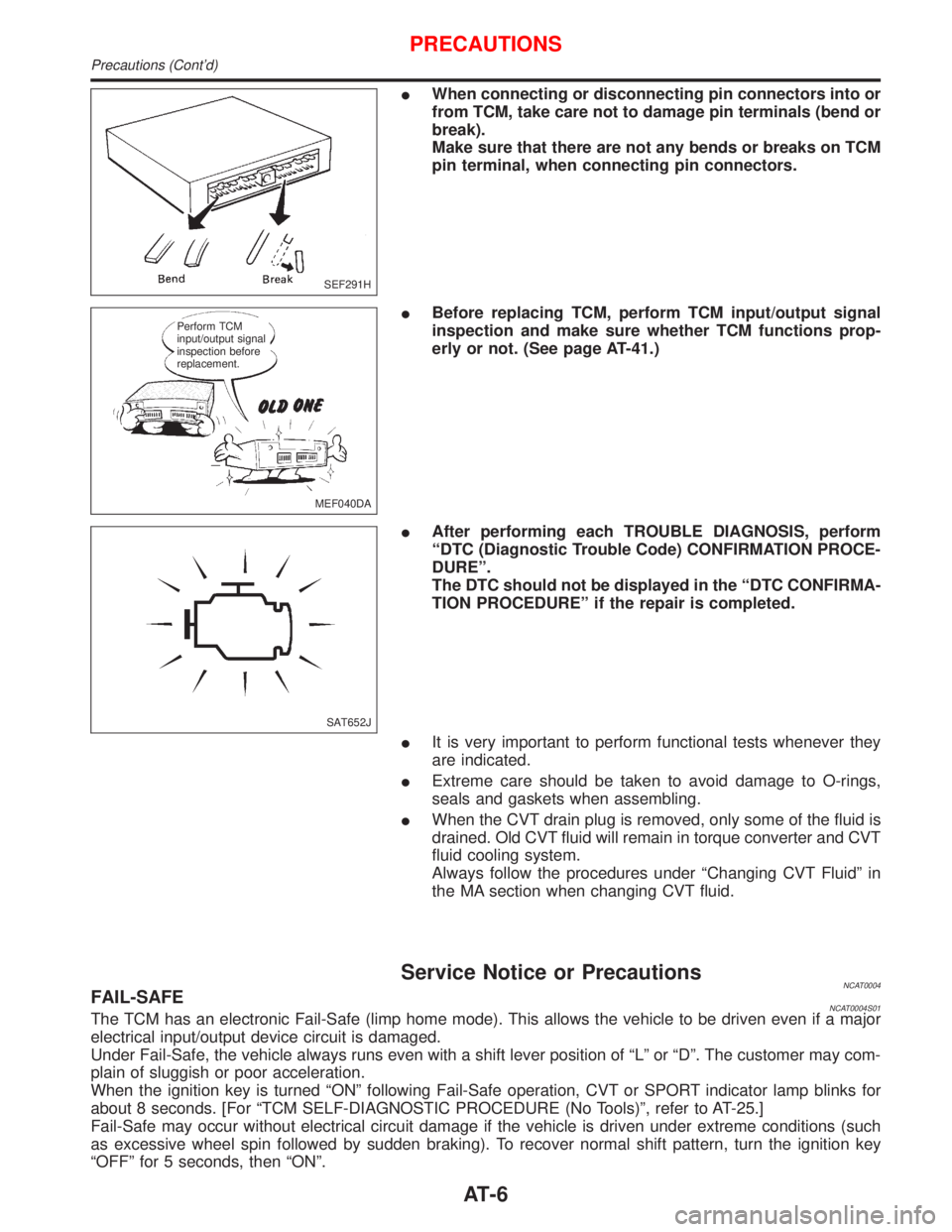
IWhen connecting or disconnecting pin connectors into or
from TCM, take care not to damage pin terminals (bend or
break).
Make sure that there are not any bends or breaks on TCM
pin terminal, when connecting pin connectors.
IBefore replacing TCM, perform TCM input/output signal
inspection and make sure whether TCM functions prop-
erly or not. (See page AT-41.)
IAfter performing each TROUBLE DIAGNOSIS, perform
ªDTC (Diagnostic Trouble Code) CONFIRMATION PROCE-
DUREº.
The DTC should not be displayed in the ªDTC CONFIRMA-
TION PROCEDUREº if the repair is completed.
IIt is very important to perform functional tests whenever they
are indicated.
IExtreme care should be taken to avoid damage to O-rings,
seals and gaskets when assembling.
IWhen the CVT drain plug is removed, only some of the fluid is
drained. Old CVT fluid will remain in torque converter and CVT
fluid cooling system.
Always follow the procedures under ªChanging CVT Fluidº in
the MA section when changing CVT fluid.
Service Notice or PrecautionsNCAT0004FAIL-SAFENCAT0004S01The TCM has an electronic Fail-Safe (limp home mode). This allows the vehicle to be driven even if a major
electrical input/output device circuit is damaged.
Under Fail-Safe, the vehicle always runs even with a shift lever position of ªLº or ªDº. The customer may com-
plain of sluggish or poor acceleration.
When the ignition key is turned ªONº following Fail-Safe operation, CVT or SPORT indicator lamp blinks for
about 8 seconds. [For ªTCM SELF-DIAGNOSTIC PROCEDURE (No Tools)º, refer to AT-25.]
Fail-Safe may occur without electrical circuit damage if the vehicle is driven under extreme conditions (such
as excessive wheel spin followed by sudden braking). To recover normal shift pattern, turn the ignition key
ªOFFº for 5 seconds, then ªONº.
SEF291H
MEF040DA Perform TCM
input/output signal
inspection before
replacement.
SAT652J
PRECAUTIONS
Precautions (Cont'd)
AT-6
Page 9 of 2267
The blinking of the CVT or SPORT indicator lamp for about 8 seconds will appear only once and be cleared.
The customer may resume normal driving conditions.
Always follow the ªWORK FLOWº (Refer to AT-32).
The SELF-DIAGNOSIS results will be as follows:
The first SELF-DIAGNOSIS will indicate damage to the vehicle speed sensor or the revolution sensor.
During the next SELF-DIAGNOSIS, performed after checking the sensor, no damages will be indicated.
OBD SELF-DIAGNOSISNCAT0004S04ICVT self-diagnosis is performed by the TCM in combination with the ECM. The results can be read through
the blinking pattern of the CVT or SPORT indicator. Refer to the table on AT-19 for the indicator used to
display each self-diagnostic result.
IThe self-diagnostic results indicated by the MI are automatically stored in both the ECM and TCM memo-
ries.
Always perform the procedure ªHOW TO ERASE DTCº on AT-16 to complete the repair and avoid
unnecessary blinking of the MI.
For details of OBD, refer to EC section (ªON BOARD DIAGNOSTIC SYSTEM DESCRIPTIONº).
ICertain systems and components, especially those related to OBD, may use a new style slide-
locking type harness connector.
For description and how to disconnect, refer to EL section, ªDescriptionº, ªHARNESS CONNEC-
TORº.
Wiring Diagrams and Trouble DiagnosisNCAT0005When you read wiring diagrams, refer to the followings:
IªHOW TO READ WIRING DIAGRAMSº in GI section
IªPOWER SUPPLY ROUTINGº for power distribution circuit in EL section
When you perform trouble diagnosis, refer to the followings:
IªHOW TO FOLLOW TEST GROUP IN TROUBLE DIAGNOSISº in GI section
IªHOW TO PERFORM EFFICIENT DIAGNOSIS FOR AN ELECTRICAL INCIDENTº in GI section
PRECAUTIONS
Service Notice or Precautions (Cont'd)
AT-7
Page 33 of 2267
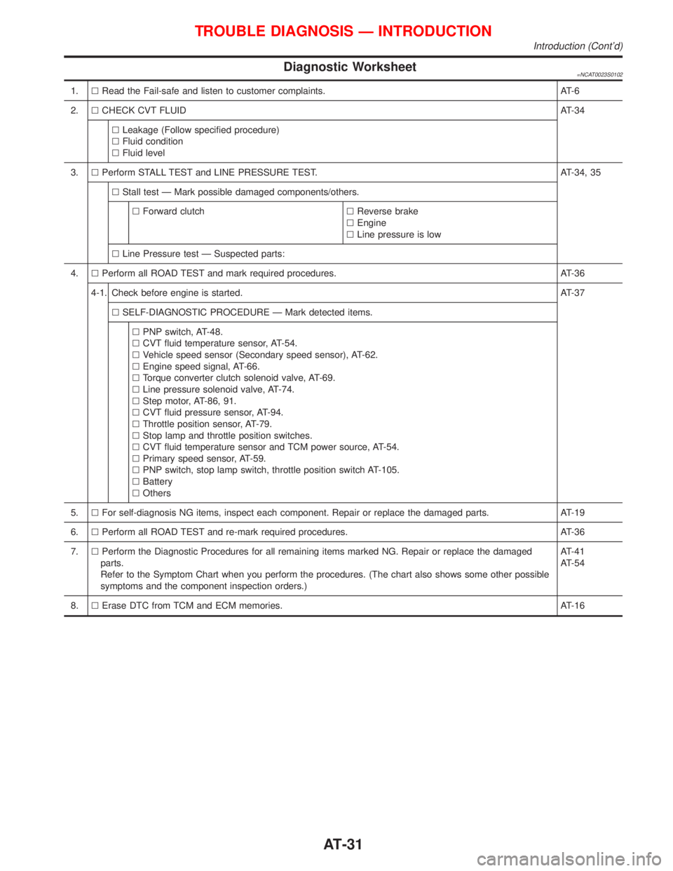
Diagnostic Worksheet=NCAT0023S0102
1.lRead the Fail-safe and listen to customer complaints. AT-6
2.lCHECK CVT FLUIDAT-34
lLeakage (Follow specified procedure)
lFluid condition
lFluid level
3.lPerform STALL TEST and LINE PRESSURE TEST. AT-34, 35
lStall test Ð Mark possible damaged components/others.
lForward clutchlReverse brake
lEngine
lLine pressure is low
lLine Pressure test Ð Suspected parts:
4.lPerform all ROAD TEST and mark required procedures. AT-36
4-1. Check before engine is started.AT-37
lSELF-DIAGNOSTIC PROCEDURE Ð Mark detected items.
lPNP switch, AT-48.
lCVT fluid temperature sensor, AT-54.
lVehicle speed sensor (Secondary speed sensor), AT-62.
lEngine speed signal, AT-66.
lTorque converter clutch solenoid valve, AT-69.
lLine pressure solenoid valve, AT-74.
lStep motor, AT-86, 91.
lCVT fluid pressure sensor, AT-94.
lThrottle position sensor, AT-79.
lStop lamp and throttle position switches.
lCVT fluid temperature sensor and TCM power source, AT-54.
lPrimary speed sensor, AT-59.
lPNP switch, stop lamp switch, throttle position switch AT-105.
lBattery
lOthers
5.lFor self-diagnosis NG items, inspect each component. Repair or replace the damaged parts. AT-19
6.lPerform all ROAD TEST and re-mark required procedures. AT-36
7.lPerform the Diagnostic Procedures for all remaining items marked NG. Repair or replace the damaged
parts.
Refer to the Symptom Chart when you perform the procedures. (The chart also shows some other possible
symptoms and the component inspection orders.)AT-41
AT-54
8.lErase DTC from TCM and ECM memories. AT-16
TROUBLE DIAGNOSIS Ð INTRODUCTION
Introduction (Cont'd)
AT-31
Page 34 of 2267
Work Flow=NCAT0024HOW TO PERFORM TROUBLE DIAGNOSES FOR QUICK AND ACCURATE REPAIRNCAT0024S01A good understanding of the malfunction conditions can make troubleshooting faster and more accurate. In
general, each customer feels differently about a problem. It is important to fully understand the symptoms or
conditions for a customer complaint.
Make good use of the two sheets provided, ªINFORMATION FROM CUSTOMERº (AT-30) and ªDIAGNOS-
TIC WORKSHEETº (AT-31), to perform the best troubleshooting possible.
TROUBLE DIAGNOSIS Ð INTRODUCTION
Work Flow
AT-32
Page 35 of 2267
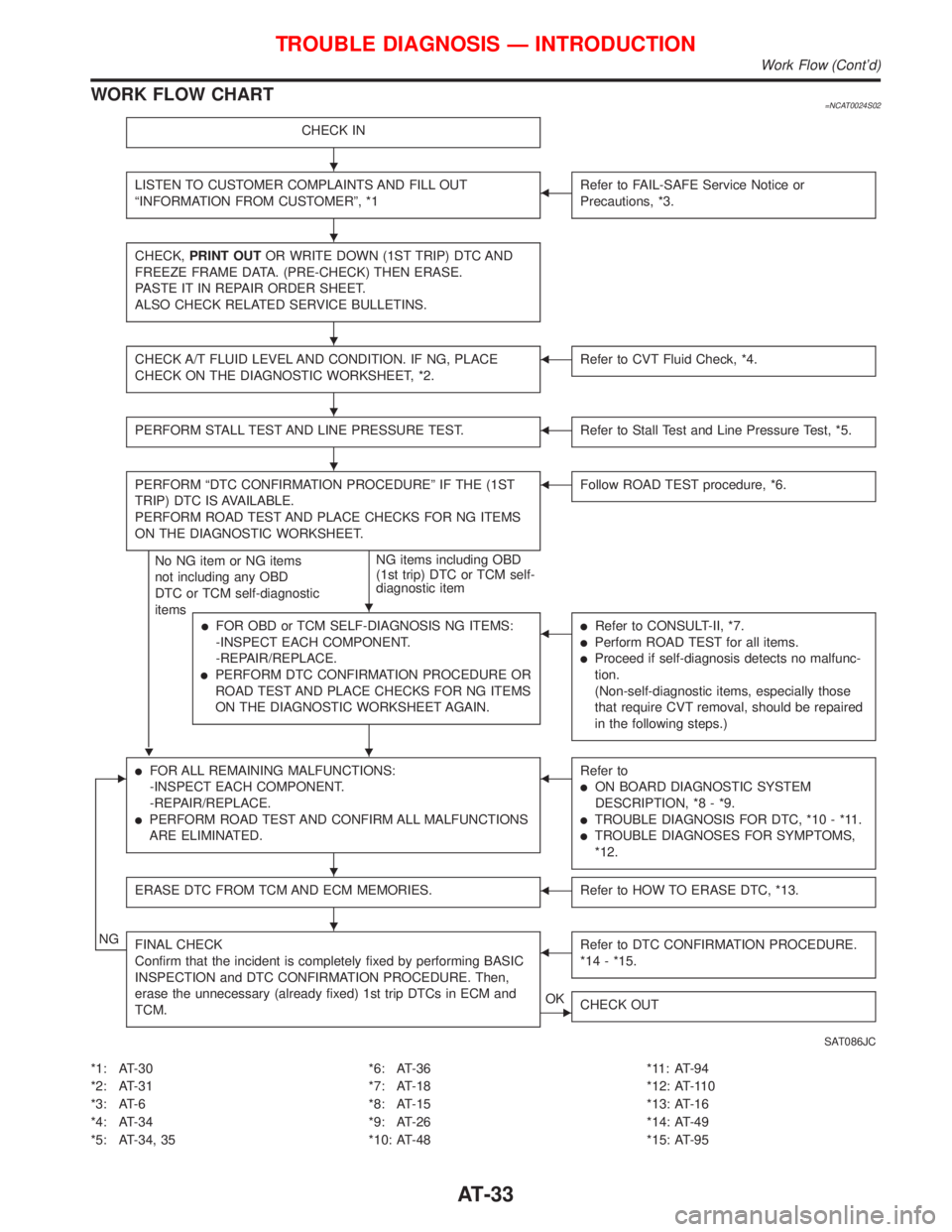
WORK FLOW CHART=NCAT0024S02
CHECK IN
LISTEN TO CUSTOMER COMPLAINTS AND FILL OUT
ªINFORMATION FROM CUSTOMERº, *1FRefer to FAIL-SAFE Service Notice or
Precautions, *3.
CHECK,PRINT OUTOR WRITE DOWN (1ST TRIP) DTC AND
FREEZE FRAME DATA. (PRE-CHECK) THEN ERASE.
PASTE IT IN REPAIR ORDER SHEET.
ALSO CHECK RELATED SERVICE BULLETINS.
CHECK A/T FLUID LEVEL AND CONDITION. IF NG, PLACE
CHECK ON THE DIAGNOSTIC WORKSHEET, *2.FRefer to CVT Fluid Check, *4.
PERFORM STALL TEST AND LINE PRESSURE TEST.FRefer to Stall Test and Line Pressure Test, *5.
PERFORM ªDTC CONFIRMATION PROCEDUREº IF THE (1ST
TRIP) DTC IS AVAILABLE.
PERFORM ROAD TEST AND PLACE CHECKS FOR NG ITEMS
ON THE DIAGNOSTIC WORKSHEET.
H
No NG item or NG items
not including any OBD
DTC or TCM self-diagnostic
itemsNG items including OBD
(1st trip) DTC or TCM self-
diagnostic item
FFollow ROAD TEST procedure, *6.
lFOR OBD or TCM SELF-DIAGNOSIS NG ITEMS:
-INSPECT EACH COMPONENT.
-REPAIR/REPLACE.
lPERFORM DTC CONFIRMATION PROCEDURE OR
ROAD TEST AND PLACE CHECKS FOR NG ITEMS
ON THE DIAGNOSTIC WORKSHEET AGAIN.
FlRefer to CONSULT-II, *7.
lPerform ROAD TEST for all items.
lProceed if self-diagnosis detects no malfunc-
tion.
(Non-self-diagnostic items, especially those
that require CVT removal, should be repaired
in the following steps.)
ElFOR ALL REMAINING MALFUNCTIONS:
-INSPECT EACH COMPONENT.
-REPAIR/REPLACE.
lPERFORM ROAD TEST AND CONFIRM ALL MALFUNCTIONS
ARE ELIMINATED.
FRefer to
lON BOARD DIAGNOSTIC SYSTEM
DESCRIPTION, *8 - *9.
lTROUBLE DIAGNOSIS FOR DTC, *10 - *11.
lTROUBLE DIAGNOSES FOR SYMPTOMS,
*12.
ERASE DTC FROM TCM AND ECM MEMORIES.FRefer to HOW TO ERASE DTC, *13.
NGFINAL CHECK
Confirm that the incident is completely fixed by performing BASIC
INSPECTION and DTC CONFIRMATION PROCEDURE. Then,
erase the unnecessary (already fixed) 1st trip DTCs in ECM and
TCM.FRefer to DTC CONFIRMATION PROCEDURE.
*14 - *15.
EOK
CHECK OUT
SAT086JC
*1: AT-30
*2: AT-31
*3: AT-6
*4: AT-34
*5: AT-34, 35*6: AT-36
*7: AT-18
*8: AT-15
*9: AT-26
*10: AT-48*11: AT-94
*12: AT-110
*13: AT-16
*14: AT-49
*15: AT-95
TROUBLE DIAGNOSIS Ð INTRODUCTION
Work Flow (Cont'd)
H
H
H
H
H
H
H
H
H
AT-33
Page 51 of 2267
DIAGNOSTIC TROUBLE CODE (DTC) CONFIRMATION
PROCEDURE
NCAT0032S03CAUTION:
Always drive vehicle at a safe speed.
NOTE:
If ªDIAGNOSTIC TROUBLE CODE CONFIRMATION PROCE-
DUREº has been previously conducted, always turn ignition
switch ªOFFº and wait at least 5 seconds before conducting
the next test.
After the repair, perform the following procedure to confirm the
malfunction is eliminated.
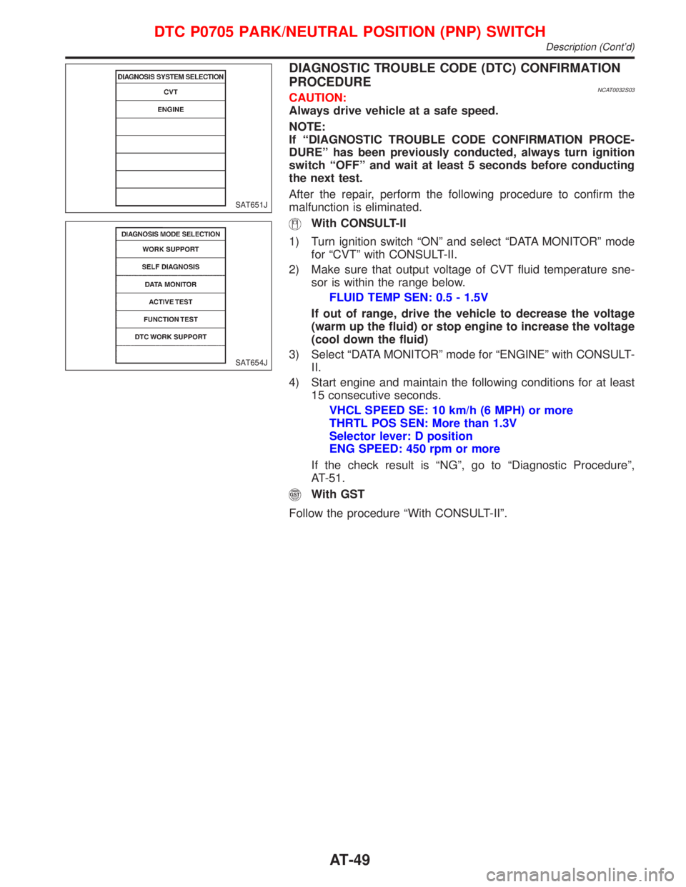
With CONSULT-II
1) Turn ignition switch ªONº and select ªDATA MONITORº mode
for ªCVTº with CONSULT-II.
2) Make sure that output voltage of CVT fluid temperature sne-
sor is within the range below.
FLUID TEMP SEN: 0.5 - 1.5V
If out of range, drive the vehicle to decrease the voltage
(warm up the fluid) or stop engine to increase the voltage
(cool down the fluid)
3) Select ªDATA MONITORº mode for ªENGINEº with CONSULT-
II.
4) Start engine and maintain the following conditions for at least
15 consecutive seconds.
VHCL SPEED SE: 10 km/h (6 MPH) or more
THRTL POS SEN: More than 1.3V
Selector lever: D position
ENG SPEED: 450 rpm or more
If the check result is ªNGº, go to ªDiagnostic Procedureº,
AT-51.
With GST
Follow the procedure ªWith CONSULT-IIº.
SAT651J
SAT654J
DTC P0705 PARK/NEUTRAL POSITION (PNP) SWITCH
Description (Cont'd)
AT-49
Page 57 of 2267
DIAGNOSTIC TROUBLE CODE (DTC) CONFIRMATION
PROCEDURE
NCAT0035S04CAUTION:
Always drive vehicle at a safe speed.
NOTE:
If ªDIAGNOSTIC TROUBLE CODE CONFIRMATION PROCE-
DUREº has been previously conducted, always turn ignition
switch ªOFFº and wait at least 5 seconds before conducting
the next test.
After the repair, perform the following procedure to confirm the
malfunction is eliminated.
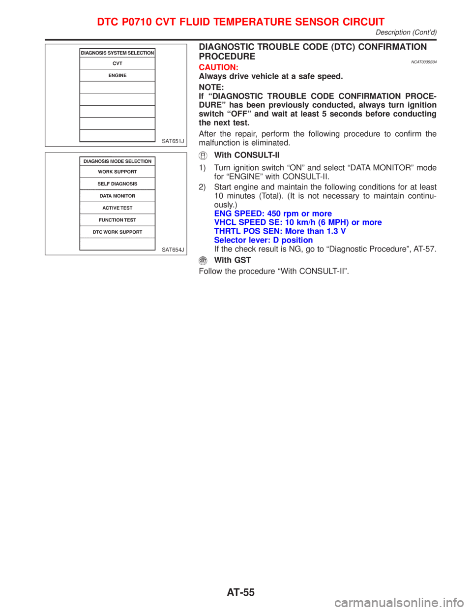
With CONSULT-II
1) Turn ignition switch ªONº and select ªDATA MONITORº mode
for ªENGINEº with CONSULT-II.
2) Start engine and maintain the following conditions for at least
10 minutes (Total). (It is not necessary to maintain continu-
ously.)
ENG SPEED: 450 rpm or more
VHCL SPEED SE: 10 km/h (6 MPH) or more
THRTL POS SEN: More than 1.3 V
Selector lever: D position
If the check result is NG, go to ªDiagnostic Procedureº, AT-57.
With GST
Follow the procedure ªWith CONSULT-IIº.
SAT651J
SAT654J
DTC P0710 CVT FLUID TEMPERATURE SENSOR CIRCUIT
Description (Cont'd)
AT-55