1999 NISSAN PRIMERA air condition
[x] Cancel search: air conditionPage 308 of 2267
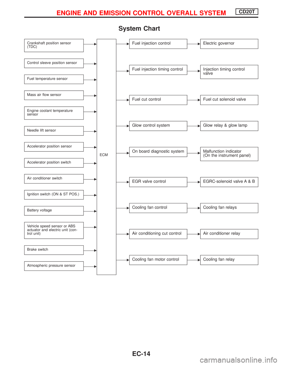
System Chart
Crankshaft position sensor
(TDC)E
ECM
Control sleeve position sensorE
Fuel temperature sensorE
Mass air flow sensorE
Engine coolant temperature
sensorE
Needle lift sensorE
Accelerator position sensorE
Accelerator position switchE
Air conditioner switchE
Ignition switch (ON & ST POS.)E
Battery voltageE
Vehicle speed sensor or ABS
actuator and electric unit (con-
trol unit)E
Brake switchE
Atmospheric pressure sensorE
EFuel injection controlEElectric governor
EFuel injection timing controlEInjection timing control
valve
EFuel cut controlEFuel cut solenoid valve
EGlow control systemEGlow relay & glow lamp
EOn board diagnostic systemEMalfunction indicator
(On the instrument panel)
EEGR valve controlEEGRC-solenoid valve A & B
ECooling fan controlECooling fan relays
EAir conditioning cut controlEAir conditioner relay
ECooling fan motor controlECooling fan relay
ENGINE AND EMISSION CONTROL OVERALL SYSTEMCD20T
EC-14
Page 310 of 2267
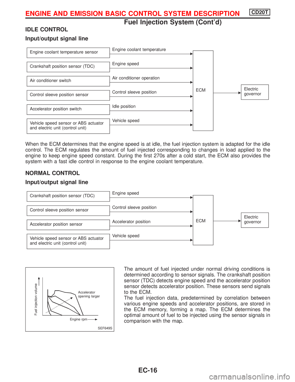
IDLE CONTROL
Input/output signal line
Engine coolant temperature sensorEEngine coolant temperature
ECM
EElectric
governor
Crankshaft position sensor (TDC)EEngine speed
Air conditioner switch
EAir conditioner operation
Control sleeve position sensor
EControl sleeve position
Accelerator position switch
EIdle position
Vehicle speed sensor or ABS actuator
and electric unit (control unit)
EVehicle speed
When the ECM determines that the engine speed is at idle, the fuel injection system is adapted for the idle
control. The ECM regulates the amount of fuel injected corresponding to changes in load applied to the
engine to keep engine speed constant. During the first 270s after a cold start, the ECM also provides the
system with a fast idle control in response to the engine coolant temperature.
NORMAL CONTROL
Input/output signal line
Crankshaft position sensor (TDC)EEngine speed
ECM
EElectric
governor
Control sleeve position sensorEControl sleeve position
Accelerator position sensor
EAccelerator position
Vehicle speed sensor or ABS actuator
and electric unit (control unit)
EVehicle speed
The amount of fuel injected under normal driving conditions is
determined according to sensor signals. The crankshaft position
sensor (TDC) detects engine speed and the accelerator position
sensor detects accelerator position. These sensors send signals
to the ECM.
The fuel injection data, predetermined by correlation between
various engine speeds and accelerator positions, are stored in
the ECM memory, forming a map. The ECM determines the
optimal amount of fuel to be injected using the sensor signals in
comparison with the map.
SEF649S
Fuel injection volume
Accelerator
opening larger
Engine rpm
ENGINE AND EMISSION BASIC CONTROL SYSTEM DESCRIPTIONCD20T
Fuel Injection System (Cont'd)
EC-16
Page 314 of 2267
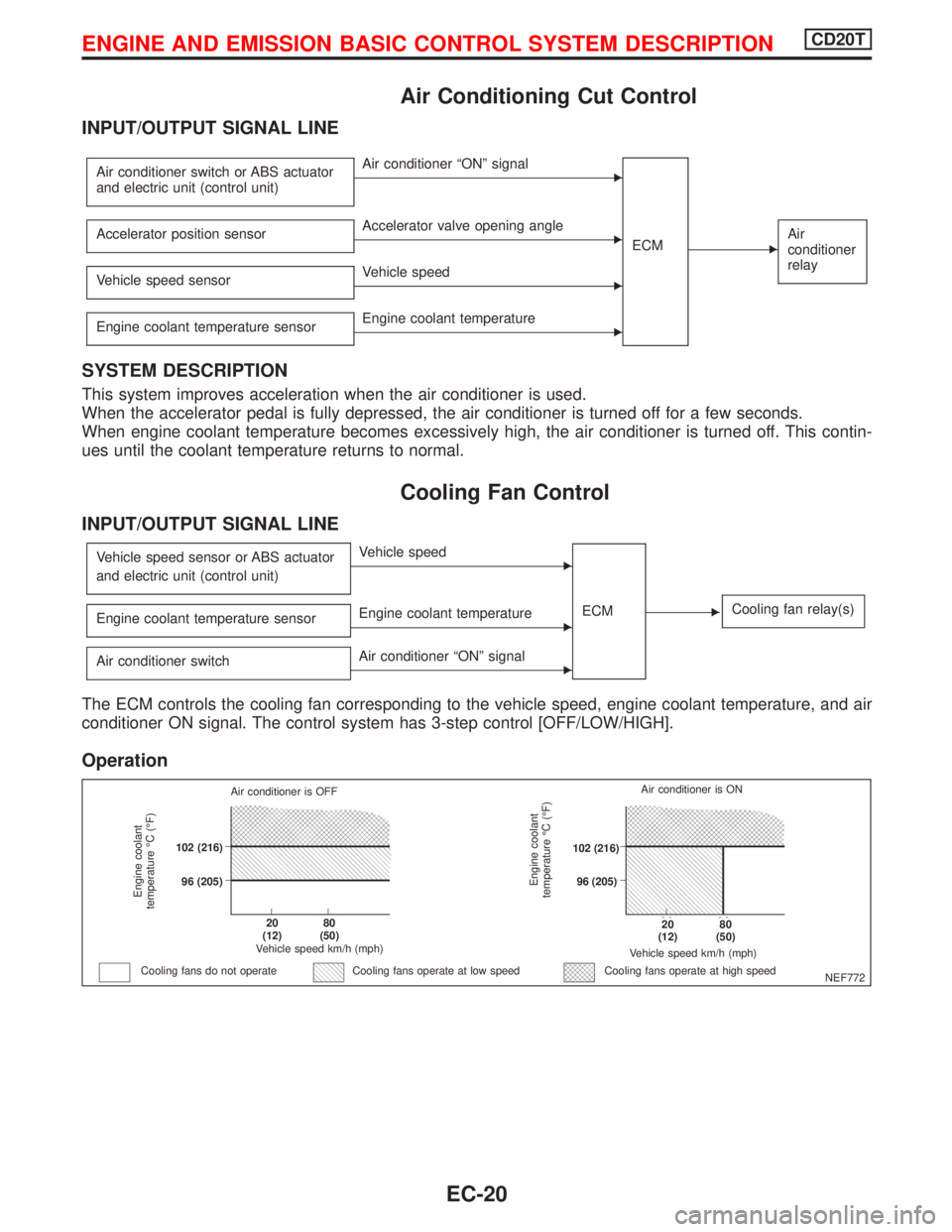
Air Conditioning Cut Control
INPUT/OUTPUT SIGNAL LINE
Air conditioner switch or ABS actuator
and electric unit (control unit)EAir conditioner ªONº signal
ECM
EAir
conditioner
relayAccelerator position sensorEAccelerator valve opening angle
Vehicle speed sensor
EVehicle speed
Engine coolant temperature sensor
EEngine coolant temperature
SYSTEM DESCRIPTION
This system improves acceleration when the air conditioner is used.
When the accelerator pedal is fully depressed, the air conditioner is turned off for a few seconds.
When engine coolant temperature becomes excessively high, the air conditioner is turned off. This contin-
ues until the coolant temperature returns to normal.
Cooling Fan Control
INPUT/OUTPUT SIGNAL LINE
Vehicle speed sensor or ABS actuator
and electric unit (control unit)EVehicle speed
ECM
ECooling fan relay(s)Engine coolant temperature sensorEEngine coolant temperature
Air conditioner switch
EAir conditioner ªONº signal
The ECM controls the cooling fan corresponding to the vehicle speed, engine coolant temperature, and air
conditioner ON signal. The control system has 3-step control [OFF/LOW/HIGH].
Operation
NEF772
Engine coolant
temperature ÉC (ÉF)
Air conditioner is OFF
.102 (216)
.96 (205)
.20
(12).80
(50)
Vehicle speed km/h (mph)
Cooling fans do not operateCooling fans operate at high speed
Engine coolant
temperature ÉC (ÉF)
Vehicle speed km/h (mph)
.20
(12).80
(50)
.102 (216)
.96 (205)Air conditioner is ON
Cooling fans operate at low speed
ENGINE AND EMISSION BASIC CONTROL SYSTEM DESCRIPTIONCD20T
EC-20
Page 322 of 2267
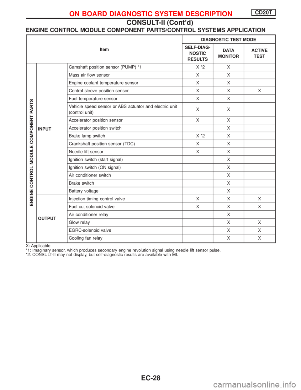
ENGINE CONTROL MODULE COMPONENT PARTS/CONTROL SYSTEMS APPLICATION
ItemDIAGNOSTIC TEST MODE
SELF-DIAG-
NOSTIC
RESULTSD ATA
MONITORACTIVE
TEST
ENGINE CONTROL MODULE COMPONENT PARTS
INPUTCamshaft position sensor (PUMP) *1 X *2 X
Mass air flow sensor X X
Engine coolant temperature sensor X X
Control sleeve position sensor X X X
Fuel temperature sensor X X
Vehicle speed sensor or ABS actuator and electric unit
(control unit)XX
Accelerator position sensor X X
Accelerator position switch X
Brake lamp switch X *2 X
Crankshaft position sensor (TDC) X X
Needle lift sensor X X
Ignition switch (start signal) X
Ignition switch (ON signal) X
Air conditioner switch X
Brake switch X
Battery voltage X
OUTPUTInjection timing control valve X X X
Fuel cut solenoid valve X X X
Air conditioner relay X
Glow relay X X
EGRC-solenoid valve X X
Cooling fan relay X X
X: Applicable
*1: Imaginary sensor, which produces secondary engine revolution signal using needle lift sensor pulse.
*2: CONSULT-II may not display, but self-diagnostic results are available with MI.
ON BOARD DIAGNOSTIC SYSTEM DESCRIPTIONCD20T
CONSULT-II (Cont'd)
EC-28
Page 323 of 2267
![NISSAN PRIMERA 1999 Electronic Repair Manual SELF-DIAGNOSTIC MODE
Regarding items detected in ªSELF-DIAG RESULTSº mode, refer to ªDiagnostic Trouble chartº.
DATA MONITOR MODE
Monitored item
[Unit]ECM
input
signalsMain
signalsDescription Rema](/manual-img/5/57377/w960_57377-322.png "NISSAN PRIMERA 1999 Electronic Repair Manual SELF-DIAGNOSTIC MODE
Regarding items detected in ªSELF-DIAG RESULTSº mode, refer to ªDiagnostic Trouble chartº.
DATA MONITOR MODE
Monitored item
[Unit]ECM
input
signalsMain
signalsDescription Rema")
SELF-DIAGNOSTIC MODE
Regarding items detected in ªSELF-DIAG RESULTSº mode, refer to ªDiagnostic Trouble chartº.
DATA MONITOR MODE
Monitored item
[Unit]ECM
input
signalsMain
signalsDescription Remarks
CKPS×RPM
(TDC) [rpm]
qq
lThe engine speed computed from the
crankshaft position sensor (TDC) sig-
nal is displayed.
CMPS×RPM -
PUMP [rpm]
qq
lThe engine speed computed from the
camshaft position sensor (PUMP) sig-
nal is displayed.
COOLAN TEMP/S
[ÉC] or [ÉF]
qq
lThe engine coolant temperature (deter-
mined by the signal voltage of the
engine coolant temperature sensor) is
displayed.lWhen the engine coolant temperature
sensor is open or short-circuited, ECM
enters fail-safe mode. The engine cool-
ant temperature determined by the
ECM is displayed.
VHCL SPEED SE
[km/h] or [mph]
qq
lThe vehicle speed computed from the
vehicle speed sensor signal or ABS
actuator and electric unit (control unit)
signal is displayed.
FUEL TEMP SEN
[ÉC] or [ÉF]
qq
lThe fuel temperature (determined by
the signal voltage of the fuel tempera-
ture sensor) is displayed.
ACCEL POS SEN
[V]
qqlThe accelerator position sensor signal
voltage is displayed.
OFF ACCEL POS
[ON/OFF]
qqlIndicates [ON/OFF] condition from the
accelerator position switch signal.
C/SLEEV POS/S [V]
qqlThe control sleeve position sensor sig-
nal voltage is displayed.
BATTERY VOLT [V]
qqlThe power supply voltage of ECM is
displayed.
START SIGNAL
[ON/OFF]
qqlIndicates [ON/OFF] condition from the
starter signal.lAfter starting the engine, [OFF] is dis-
played regardless of the starter signal.
AIR COND SIG
[ON/OFF]
qq
lIndicates [ON/OFF] condition of the air
conditioner switch as determined by
the air conditioner signal.
BRAKE SW
[ON/OFF]
qlIndicates [ON/OFF] condition of the
stio lamp switch.
BRAKE SW2
[ON/OFF]
qlIndicates [ON/OFF] condition of the
stio lamp switch 2.
IGN SW
[ON/OFF]
qqlIndicates [ON/OFF] condition from igni-
tion switch.
MAS AIR/FL SE [V]
qqlThe signal voltage of the mass air flow
sensor is displayed.lWhen the engine is stopped, a certain
value is indicated.
ACT INJ TIMG [É]
q
lThe actual injection timing angle deter-
mined by the ECM (an approximate
average angle between injection start
and end from TDC) is displayed.
TARGET F/INJ
[mm
3/STROKE]q
lThe target fuel injection quantity
(determined by the ECM according to
the input signal) is indicated.
NOTE:
Any monitored item that does not match the vehicle being diagnosed is deleted from the display automatically.
ON BOARD DIAGNOSTIC SYSTEM DESCRIPTIONCD20T
CONSULT-II (Cont'd)
EC-29
Page 324 of 2267
![NISSAN PRIMERA 1999 Electronic Repair Manual Monitored item
[Unit]ECM
input
signalsMain
signalsDescription Remarks
FUEL CUT S/V
[ON/OFF]
lThe control condition of the fuel cut
solenoid valve (determined by ECM
according to the input signal) is i](/manual-img/5/57377/w960_57377-323.png "NISSAN PRIMERA 1999 Electronic Repair Manual Monitored item
[Unit]ECM
input
signalsMain
signalsDescription Remarks
FUEL CUT S/V
[ON/OFF]
lThe control condition of the fuel cut
solenoid valve (determined by ECM
according to the input signal) is i")
Monitored item
[Unit]ECM
input
signalsMain
signalsDescription Remarks
FUEL CUT S/V
[ON/OFF]
lThe control condition of the fuel cut
solenoid valve (determined by ECM
according to the input signal) is indi-
cated.
lOFF ... Fuel cut solenoid valve is not
operating.
ON ... Fuel cut solenoid valve is oper-
ating.
lWhen the fuel cut solenoid valve is not
operating, fuel supply is shut off.
AIR COND RLY
[ON/OFF]
q
lThe air conditioner relay control condi-
tion (determined by ECM according to
the input signal) is indicated.
GLOW RLY
[ON/OFF]
q
lThe glow relay control condition (deter-
mined by ECM according to the input
signal) is displayed.
COOLING FAN
[LOW/HI/OFF]
q
lIndicates the control condition of the
cooling fans (determined by ECM
according to the input signal).
lLOW ... Operates at low speed.
HI ... Operates at high speed.
OFF ... Stopped.
EGRC SOL/V A
[ON/OFF]
lThe control condition of the EGRC-
solenoid valve (determined by ECM
according to the input signal) is indi-
cated.
lOFF ... EGRC-solenoid valve is not
operating.
ON ... EGRC-solenoid valve is oper-
ating.
ON BOARD DIAGNOSTIC SYSTEM DESCRIPTIONCD20T
CONSULT-II (Cont'd)
EC-30
Page 329 of 2267
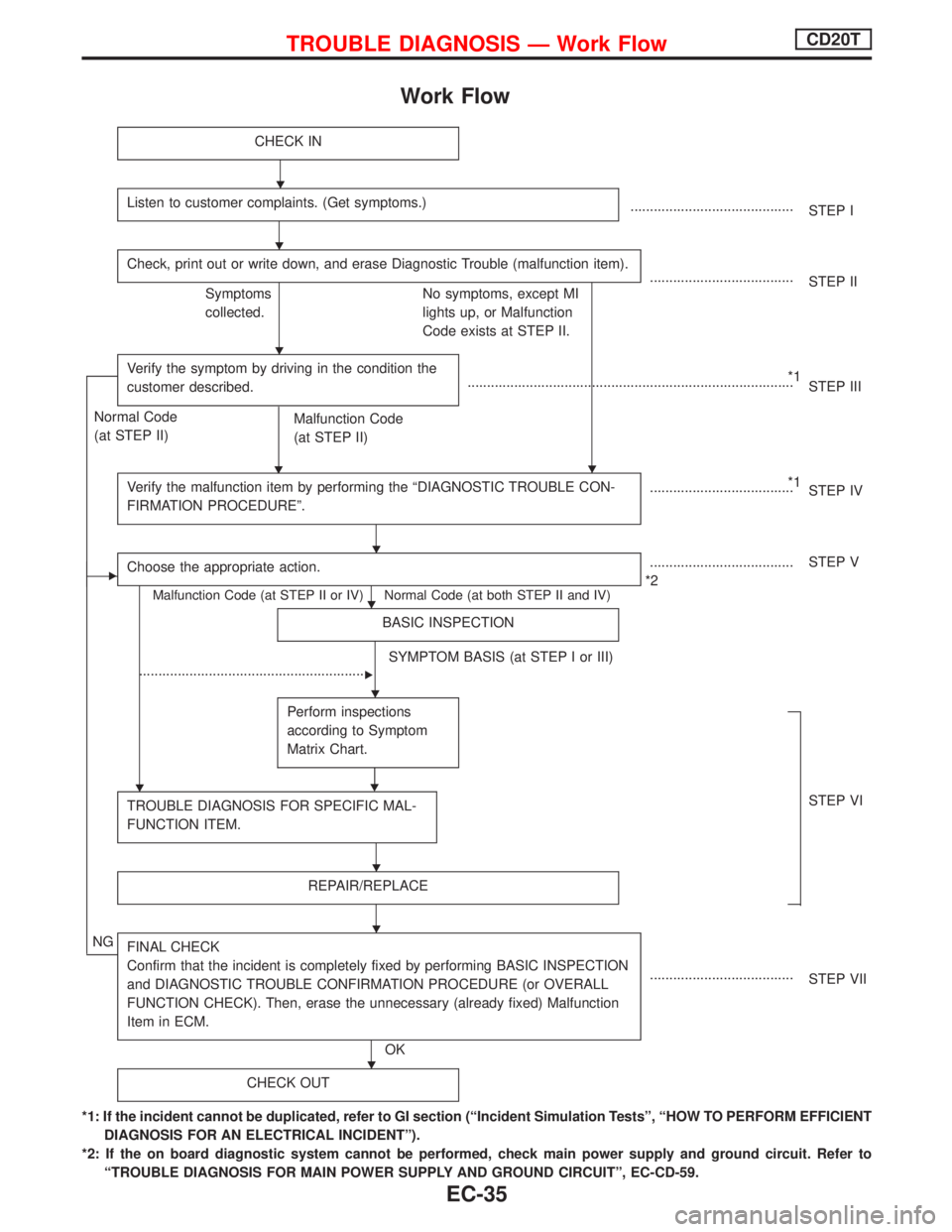
Work Flow
CHECK IN
Listen to customer complaints. (Get symptoms.)..........................................
STEP I
Check, print out or write down, and erase Diagnostic Trouble (malfunction item).
.....................................
STEP II
Symptoms
collected.No symptoms, except MI
lights up, or Malfunction
Code exists at STEP II.
Verify the symptom by driving in the condition the
customer described.
H
*1
....................................................................................
STEP III
Normal Code
(at STEP II)
Malfunction Code
(at STEP II)
Verify the malfunction item by performing the ªDIAGNOSTIC TROUBLE CON-
FIRMATION PROCEDUREº.
*1
.....................................
STEP IV
EChoose the appropriate action.
Malfunction Code (at STEP II or IV) Normal Code (at both STEP II and IV)
.....................................
*2STEP V
BASIC INSPECTION
SYMPTOM BASIS (at STEP I or III)
...........................................................
E
Perform inspections
according to Symptom
Matrix Chart.
H
TROUBLE DIAGNOSIS FOR SPECIFIC MAL-
FUNCTION ITEM.STEP VI
REPAIR/REPLACE
NGFINAL CHECK
Confirm that the incident is completely fixed by performing BASIC INSPECTION
and DIAGNOSTIC TROUBLE CONFIRMATION PROCEDURE (or OVERALL
FUNCTION CHECK). Then, erase the unnecessary (already fixed) Malfunction
Item in ECM.
OK.....................................
STEP VII
CHECK OUT
*1: If the incident cannot be duplicated, refer to GI section (ªIncident Simulation Testsº, ªHOW TO PERFORM EFFICIENT
DIAGNOSIS FOR AN ELECTRICAL INCIDENTº).
*2: If the on board diagnostic system cannot be performed, check main power supply and ground circuit. Refer to
ªTROUBLE DIAGNOSIS FOR MAIN POWER SUPPLY AND GROUND CIRCUITº, EC-CD-59.
H
H
H
H
H
H
H
H
H
H
H
TROUBLE DIAGNOSIS Ð Work FlowCD20T
EC-35
Page 330 of 2267
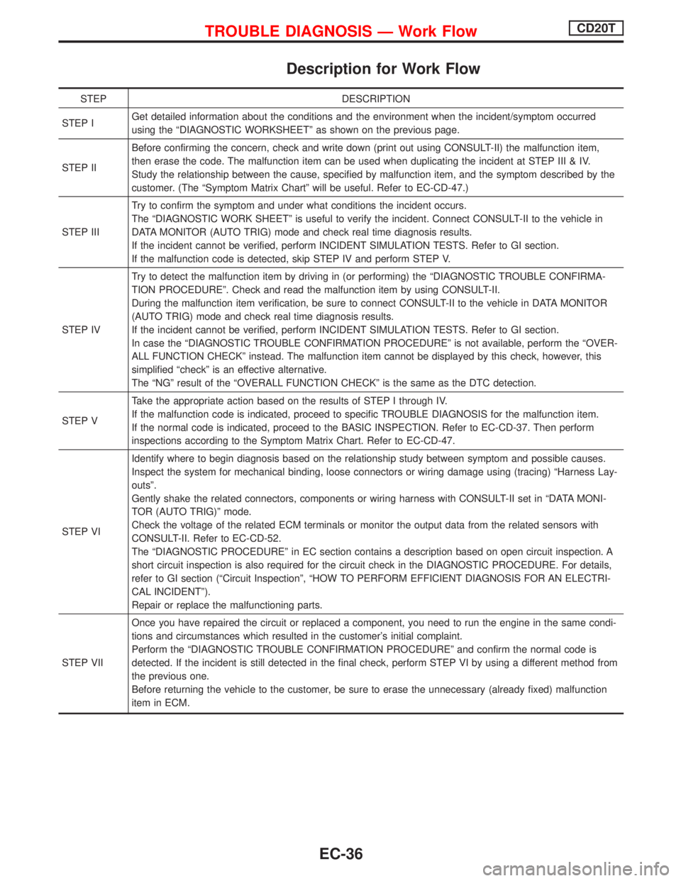
Description for Work Flow
STEP DESCRIPTION
STEP IGet detailed information about the conditions and the environment when the incident/symptom occurred
using the ªDIAGNOSTIC WORKSHEETº as shown on the previous page.
STEP IIBefore confirming the concern, check and write down (print out using CONSULT-II) the malfunction item,
then erase the code. The malfunction item can be used when duplicating the incident at STEP III & IV.
Study the relationship between the cause, specified by malfunction item, and the symptom described by the
customer. (The ªSymptom Matrix Chartº will be useful. Refer to EC-CD-47.)
STEP IIITry to confirm the symptom and under what conditions the incident occurs.
The ªDIAGNOSTIC WORK SHEETº is useful to verify the incident. Connect CONSULT-II to the vehicle in
DATA MONITOR (AUTO TRIG) mode and check real time diagnosis results.
If the incident cannot be verified, perform INCIDENT SIMULATION TESTS. Refer to GI section.
If the malfunction code is detected, skip STEP IV and perform STEP V.
STEP IVTry to detect the malfunction item by driving in (or performing) the ªDIAGNOSTIC TROUBLE CONFIRMA-
TION PROCEDUREº. Check and read the malfunction item by using CONSULT-II.
During the malfunction item verification, be sure to connect CONSULT-II to the vehicle in DATA MONITOR
(AUTO TRIG) mode and check real time diagnosis results.
If the incident cannot be verified, perform INCIDENT SIMULATION TESTS. Refer to GI section.
In case the ªDIAGNOSTIC TROUBLE CONFIRMATION PROCEDUREº is not available, perform the ªOVER-
ALL FUNCTION CHECKº instead. The malfunction item cannot be displayed by this check, however, this
simplified ªcheckº is an effective alternative.
The ªNGº result of the ªOVERALL FUNCTION CHECKº is the same as the DTC detection.
STEP VTake the appropriate action based on the results of STEP I through IV.
If the malfunction code is indicated, proceed to specific TROUBLE DIAGNOSIS for the malfunction item.
If the normal code is indicated, proceed to the BASIC INSPECTION. Refer to EC-CD-37. Then perform
inspections according to the Symptom Matrix Chart. Refer to EC-CD-47.
STEP VIIdentify where to begin diagnosis based on the relationship study between symptom and possible causes.
Inspect the system for mechanical binding, loose connectors or wiring damage using (tracing) ªHarness Lay-
outsº.
Gently shake the related connectors, components or wiring harness with CONSULT-II set in ªDATA MONI-
TOR (AUTO TRIG)º mode.
Check the voltage of the related ECM terminals or monitor the output data from the related sensors with
CONSULT-II. Refer to EC-CD-52.
The ªDIAGNOSTIC PROCEDUREº in EC section contains a description based on open circuit inspection. A
short circuit inspection is also required for the circuit check in the DIAGNOSTIC PROCEDURE. For details,
refer to GI section (ªCircuit Inspectionº, ªHOW TO PERFORM EFFICIENT DIAGNOSIS FOR AN ELECTRI-
CAL INCIDENTº).
Repair or replace the malfunctioning parts.
STEP VIIOnce you have repaired the circuit or replaced a component, you need to run the engine in the same condi-
tions and circumstances which resulted in the customer's initial complaint.
Perform the ªDIAGNOSTIC TROUBLE CONFIRMATION PROCEDUREº and confirm the normal code is
detected. If the incident is still detected in the final check, perform STEP VI by using a different method from
the previous one.
Before returning the vehicle to the customer, be sure to erase the unnecessary (already fixed) malfunction
item in ECM.
TROUBLE DIAGNOSIS Ð Work FlowCD20T
EC-36