1999 NISSAN PRIMERA water pump
[x] Cancel search: water pumpPage 318 of 2267
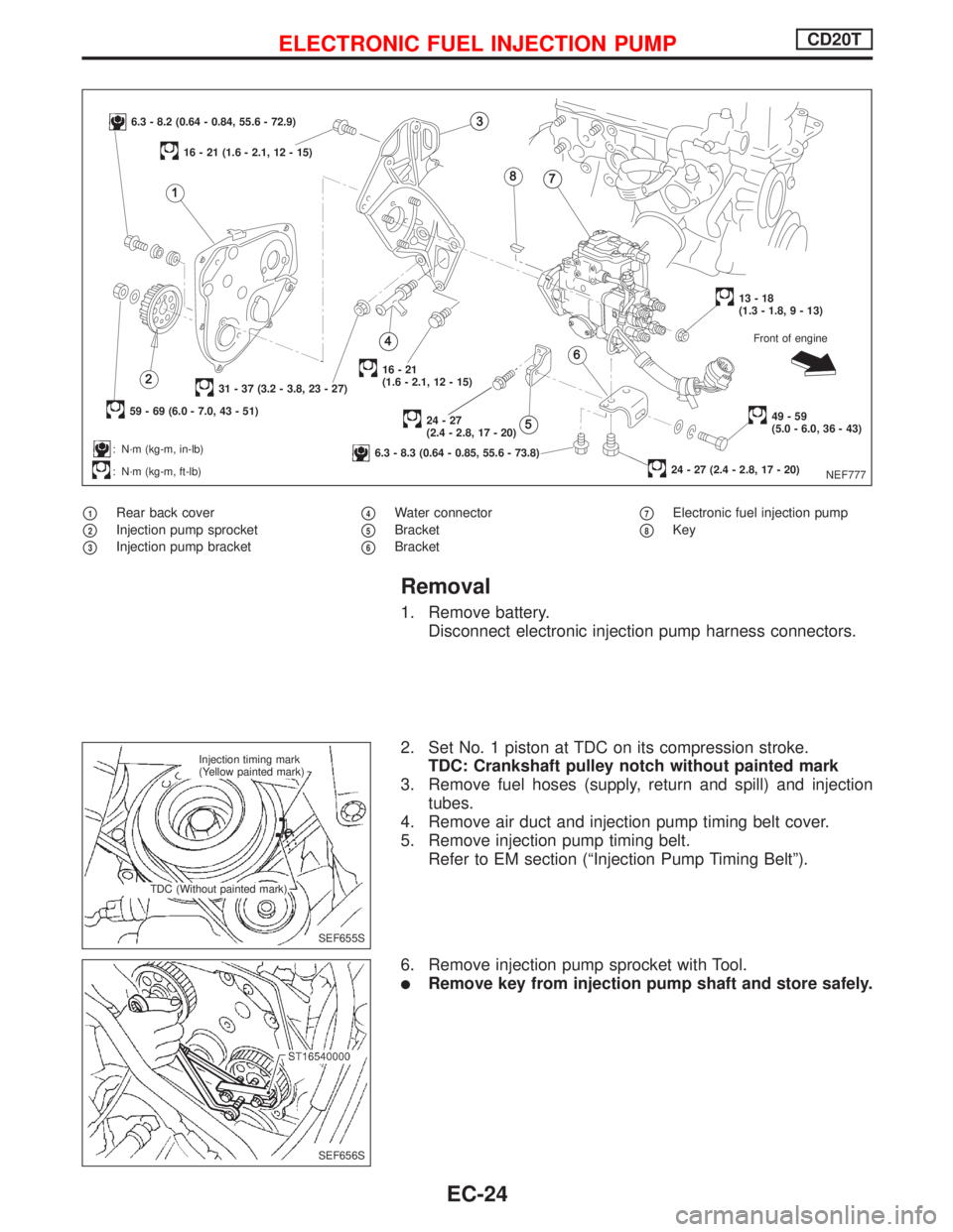
p1Rear back cover
p2Injection pump sprocket
p3Injection pump bracket
p4Water connector
p5Bracket
p6Bracket
p7Electronic fuel injection pump
p8Key
Removal
1. Remove battery.
Disconnect electronic injection pump harness connectors.
2. Set No. 1 piston at TDC on its compression stroke.
TDC: Crankshaft pulley notch without painted mark
3. Remove fuel hoses (supply, return and spill) and injection
tubes.
4. Remove air duct and injection pump timing belt cover.
5. Remove injection pump timing belt.
Refer to EM section (ªInjection Pump Timing Beltº).
6. Remove injection pump sprocket with Tool.
lRemove key from injection pump shaft and store safely.
NEF777
6.3 - 8.2 (0.64 - 0.84, 55.6 - 72.9)
59 - 69 (6.0 - 7.0, 43 - 51)
31 - 37 (3.2 - 3.8, 23 - 27)
: N´m (kg-m, in-lb)
: N´m (kg-m, ft-lb)
16 - 21 (1.6 - 2.1, 12 - 15)
16-21
(1.6 - 2.1, 12 - 15)
24-27
(2.4 - 2.8, 17 - 20)
6.3 - 8.3 (0.64 - 0.85, 55.6 - 73.8)
13-18
(1.3 - 1.8, 9 - 13)
49-59
(5.0 - 6.0, 36 - 43)
24 - 27 (2.4 - 2.8, 17 - 20)Front of engine
SEF655S Injection timing mark
(Yellow painted mark)
TDC (Without painted mark)
SEF656S
ELECTRONIC FUEL INJECTION PUMPCD20T
EC-24
Page 332 of 2267
pA
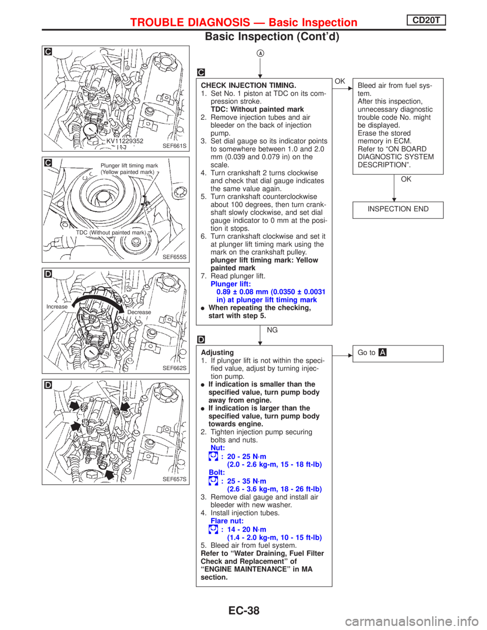
CHECK INJECTION TIMING.
1. Set No. 1 piston at TDC on its com-
pression stroke.
TDC: Without painted mark
2. Remove injection tubes and air
bleeder on the back of injection
pump.
3. Set dial gauge so its indicator points
to somewhere between 1.0 and 2.0
mm (0.039 and 0.079 in) on the
scale.
4. Turn crankshaft 2 turns clockwise
and check that dial gauge indicates
the same value again.
5. Turn crankshaft counterclockwise
about 100 degrees, then turn crank-
shaft slowly clockwise, and set dial
gauge indicator to 0 mm at the posi-
tion it stops.
6. Turn crankshaft clockwise and set it
at plunger lift timing mark using the
mark on the crankshaft pulley.
plunger lift timing mark: Yellow
painted mark
7. Read plunger lift.
Plunger lift:
0.89 0.08 mm (0.0350 0.0031
in) at plunger lift timing mark
lWhen repeating the checking,
start with step 5.
NG
EOK
Bleed air from fuel sys-
tem.
After this inspection,
unnecessary diagnostic
trouble code No. might
be displayed.
Erase the stored
memory in ECM.
Refer to ªON BOARD
DIAGNOSTIC SYSTEM
DESCRIPTIONº.
OK
INSPECTION END
Adjusting
1. If plunger lift is not within the speci-
fied value, adjust by turning injec-
tion pump.
lIf indication is smaller than the
specified value, turn pump body
away from engine.
lIf indication is larger than the
specified value, turn pump body
towards engine.
2. Tighten injection pump securing
bolts and nuts.
Nut:
: 20-25N´m
(2.0 - 2.6 kg-m, 15 - 18 ft-lb)
Bolt:
: 25-35N´m
(2.6 - 3.6 kg-m, 18 - 26 ft-lb)
3. Remove dial gauge and install air
bleeder with new washer.
4. Install injection tubes.
Flare nut:
: 14-20N´m
(1.4 - 2.0 kg-m, 10 - 15 ft-lb)
5. Bleed air from fuel system.
Refer to ªWater Draining, Fuel Filter
Check and Replacementº of
ªENGINE MAINTENANCEº in MA
section.
EGo to
SEF661S
SEF655S
Plunger lift timing mark
(Yellow painted mark)
TDC (Without painted mark)
SEF662S
Increase
Decrease
SEF657S
H
H
H
TROUBLE DIAGNOSIS Ð Basic InspectionCD20T
Basic Inspection (Cont'd)
EC-38
Page 336 of 2267
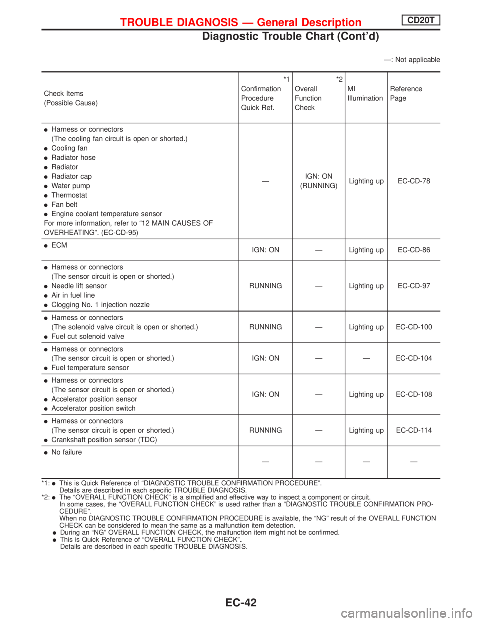
Ð: Not applicable
Check Items
(Possible Cause)*1
Confirmation
Procedure
Quick Ref.*2
Overall
Function
CheckMI
IlluminationReference
Page
lHarness or connectors
(The cooling fan circuit is open or shorted.)
lCooling fan
lRadiator hose
lRadiator
lRadiator cap
lWater pump
lThermostat
lFan belt
lEngine coolant temperature sensor
For more information, refer to ª12 MAIN CAUSES OF
OVERHEATINGº. (EC-CD-95)ÐIGN: ON
(RUNNING)Lighting up EC-CD-78
lECM
IGN: ON Ð Lighting up EC-CD-86
lHarness or connectors
(The sensor circuit is open or shorted.)
lNeedle lift sensor
lAir in fuel line
lClogging No. 1 injection nozzleRUNNING Ð Lighting up EC-CD-97
lHarness or connectors
(The solenoid valve circuit is open or shorted.)
lFuel cut solenoid valveRUNNING Ð Lighting up EC-CD-100
lHarness or connectors
(The sensor circuit is open or shorted.)
lFuel temperature sensorIGN: ON Ð Ð EC-CD-104
lHarness or connectors
(The sensor circuit is open or shorted.)
lAccelerator position sensor
lAccelerator position switchIGN: ON Ð Lighting up EC-CD-108
lHarness or connectors
(The sensor circuit is open or shorted.)
lCrankshaft position sensor (TDC)RUNNING Ð Lighting up EC-CD-114
lNo failure
Ð ÐÐÐ
*1:lThis is Quick Reference of ªDIAGNOSTIC TROUBLE CONFIRMATION PROCEDUREº.
Details are described in each specific TROUBLE DIAGNOSIS.
*2:
lThe ªOVERALL FUNCTION CHECKº is a simplified and effective way to inspect a component or circuit.
In some cases, the ªOVERALL FUNCTION CHECKº is used rather than a ªDIAGNOSTIC TROUBLE CONFIRMATION PRO-
CEDUREº.
When no DIAGNOSTIC TROUBLE CONFIRMATION PROCEDURE is available, the ªNGº result of the OVERALL FUNCTION
CHECK can be considered to mean the same as a malfunction item detection.
lDuring an ªNGº OVERALL FUNCTION CHECK, the malfunction item might not be confirmed.lThis is Quick Reference of ªOVERALL FUNCTION CHECKº.
Details are described in each specific TROUBLE DIAGNOSIS.
TROUBLE DIAGNOSIS Ð General DescriptionCD20T
Diagnostic Trouble Chart (Cont'd)
EC-42
Page 381 of 2267
Cooling Fan (Overheat)
SYSTEM DESCRIPTION
Vehicle speed sensorEVehicle speed
ECM
ECooling
fan
relay(s)Engine coolant temperature sensorEEngine coolant temperature
Air conditioner switch
EAir conditioner ªONº signal
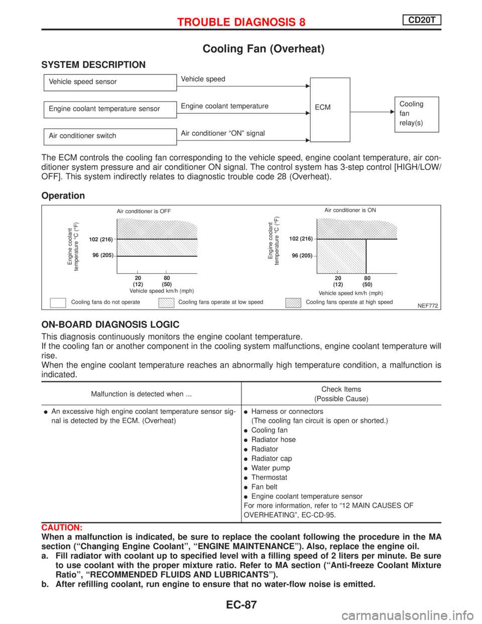
The ECM controls the cooling fan corresponding to the vehicle speed, engine coolant temperature, air con-
ditioner system pressure and air conditioner ON signal. The control system has 3-step control [HIGH/LOW/
OFF]. This system indirectly relates to diagnostic trouble code 28 (Overheat).
Operation
ON-BOARD DIAGNOSIS LOGIC
This diagnosis continuously monitors the engine coolant temperature.
If the cooling fan or another component in the cooling system malfunctions, engine coolant temperature will
rise.
When the engine coolant temperature reaches an abnormally high temperature condition, a malfunction is
indicated.
Malfunction is detected when ...Check Items
(Possible Cause)
lAn excessive high engine coolant temperature sensor sig-
nal is detected by the ECM. (Overheat)lHarness or connectors
(The cooling fan circuit is open or shorted.)
lCooling fan
lRadiator hose
lRadiator
lRadiator cap
lWater pump
lThermostat
lFan belt
lEngine coolant temperature sensor
For more information, refer to ª12 MAIN CAUSES OF
OVERHEATINGº, EC-CD-95.
CAUTION:
When a malfunction is indicated, be sure to replace the coolant following the procedure in the MA
section (ªChanging Engine Coolantº, ªENGINE MAINTENANCEº). Also, replace the engine oil.
a. Fill radiator with coolant up to specified level with a filling speed of 2 liters per minute. Be sure
to use coolant with the proper mixture ratio. Refer to MA section (ªAnti-freeze Coolant Mixture
Ratioº, ªRECOMMENDED FLUIDS AND LUBRICANTSº).
b. After refilling coolant, run engine to ensure that no water-flow noise is emitted.
NEF772
Engine coolant
temperature ÉC (ÉF)
Air conditioner is OFF
.102 (216)
.96 (205)
.20
(12).80
(50)
Vehicle speed km/h (mph)
Cooling fans do not operateCooling fans operate at high speed
Engine coolant
temperature ÉC (ÉF)
Vehicle speed km/h (mph)
.20
(12).80
(50)
.102 (216)
.96 (205)Air conditioner is ON
Cooling fans operate at low speed
TROUBLE DIAGNOSIS 8CD20T
EC-87
Page 388 of 2267
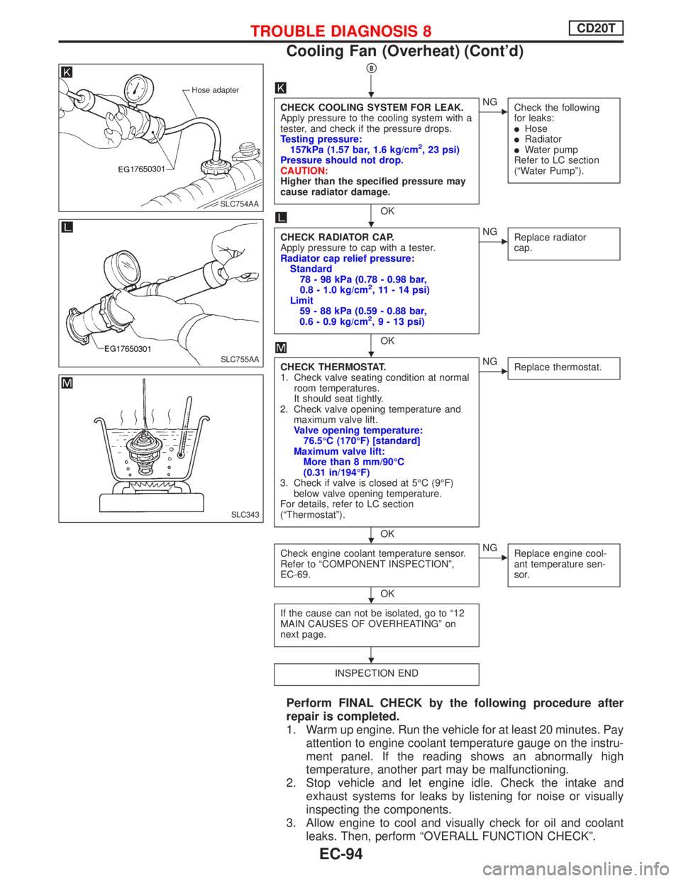
pB
CHECK COOLING SYSTEM FOR LEAK.
Apply pressure to the cooling system with a
tester, and check if the pressure drops.
Testing pressure:
157kPa (1.57 bar, 1.6 kg/cm
2, 23 psi)
Pressure should not drop.
CAUTION:
Higher than the specified pressure may
cause radiator damage.
OK
ENG
Check the following
for leaks:
lHoselRadiatorlWater pump
Refer to LC section
(ªWater Pumpº).
CHECK RADIATOR CAP.
Apply pressure to cap with a tester.
Radiator cap relief pressure:
Standard
78 - 98 kPa (0.78 - 0.98 bar,
0.8 - 1.0 kg/cm
2, 11 - 14 psi)
Limit
59 - 88 kPa (0.59 - 0.88 bar,
0.6 - 0.9 kg/cm
2,9-13psi)
OK
ENG
Replace radiator
cap.
CHECK THERMOSTAT.
1. Check valve seating condition at normal
room temperatures.
It should seat tightly.
2. Check valve opening temperature and
maximum valve lift.
Valve opening temperature:
76.5ÉC (170ÉF) [standard]
Maximum valve lift:
More than 8 mm/90ÉC
(0.31 in/194ÉF)
3. Check if valve is closed at 5ÉC (9ÉF)
below valve opening temperature.
For details, refer to LC section
(ªThermostatº).
OK
ENG
Replace thermostat.
Check engine coolant temperature sensor.
Refer to ªCOMPONENT INSPECTIONº,
EC-69.
OK
ENG
Replace engine cool-
ant temperature sen-
sor.
If the cause can not be isolated, go to ª12
MAIN CAUSES OF OVERHEATINGº on
next page.
INSPECTION END
Perform FINAL CHECK by the following procedure after
repair is completed.
1. Warm up engine. Run the vehicle for at least 20 minutes. Pay
attention to engine coolant temperature gauge on the instru-
ment panel. If the reading shows an abnormally high
temperature, another part may be malfunctioning.
2. Stop vehicle and let engine idle. Check the intake and
exhaust systems for leaks by listening for noise or visually
inspecting the components.
3. Allow engine to cool and visually check for oil and coolant
leaks. Then, perform ªOVERALL FUNCTION CHECKº.
Hose adapter
.SLC754AA
SLC755AA
SLC343
H
H
H
H
H
H
TROUBLE DIAGNOSIS 8CD20T
Cooling Fan (Overheat) (Cont'd)
EC-94
Page 524 of 2267
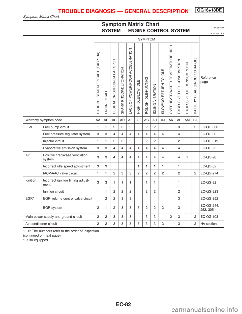
Symptom Matrix ChartNCEC0041SYSTEM Ð ENGINE CONTROL SYSTEMNCEC0041S01
SYMPTOM
Reference
page
HARD/NO START/RESTART (EXCP. HA)
ENGINE STALL
HESITATION/SURGING/FLAT SPOT
SPARK KNOCK/DETONATION
LACK OF POWER/POOR ACCELERATION
HIGH IDLE/LOW IDLE
ROUGH IDLE/HUNTING
IDLING VIBRATION
SLOW/NO RETURN TO IDLE
OVERHEATS/WATER TEMPERATURE HIGH
EXCESSIVE FUEL CONSUMPTION
EXCESSIVE OIL CONSUMPTION
BATTERY DEAD (UNDER CHARGE)
Warranty symptom code AA AB AC AD AE AF AG AH AJ AK AL AM HA
Fuel Fuel pump circuit11232 22 3 2EC-QG-336
Fuel pressure regulator system334444444 4EC-QG-30
Injector circuit11232 22 2EC-QG-319
Evaporative emission system334444444 4EC-QG-25
Air Positive crankcase ventilation
system334444444 41EC-QG-28
Incorrect idle speed adjustment 3 31111 1EC-QG-32
IACV-AAC valve circuit112332222 2 2EC-QG-274
Ignition Incorrect ignition timing adjust-
ment33111 11 1EC-QG-32
Ignition circuit11222 22 2EC-QG-323
EGR* EGR volume control valve circuit2233 3EC-QG-252
EGR system212333223 3EC-QG-244,
252, 305
Main power supply and ground circuit22333 33 23 2EC-QG-103
Air conditioner circuit223333333 3 2HAsection
1 - 6: The numbers refer to the order of inspection.
(continued on next page)
*: If so equipped
TROUBLE DIAGNOSIS Ð GENERAL DESCRIPTIONQG16I18DE
Symptom Matrix Chart
EC-82
Page 527 of 2267
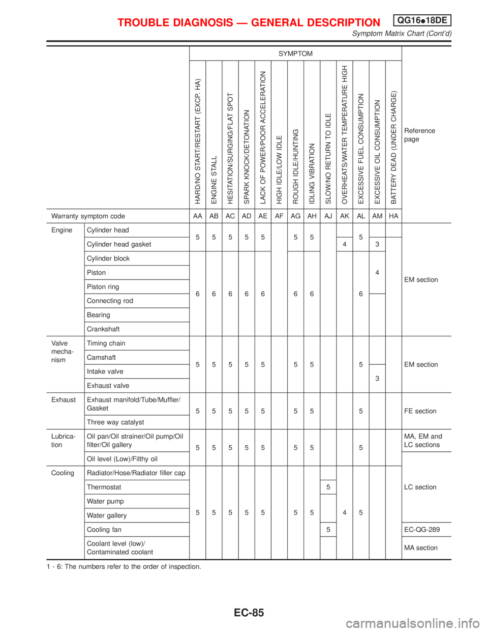
SYMPTOM
Reference
page
HARD/NO START/RESTART (EXCP. HA)
ENGINE STALL
HESITATION/SURGING/FLAT SPOT
SPARK KNOCK/DETONATION
LACK OF POWER/POOR ACCELERATION
HIGH IDLE/LOW IDLE
ROUGH IDLE/HUNTING
IDLING VIBRATION
SLOW/NO RETURN TO IDLE
OVERHEATS/WATER TEMPERATURE HIGH
EXCESSIVE FUEL CONSUMPTION
EXCESSIVE OIL CONSUMPTION
BATTERY DEAD (UNDER CHARGE)
Warranty symptom code AA AB AC AD AE AF AG AH AJ AK AL AM HA
Engine Cylinder head
55555 55 5
EM section Cylinder head gasket 4 3
Cylinder block
66666 66 64 Piston
Piston ring
Connecting rod
Bearing
Crankshaft
Valve
mecha-
nismTiming chain
55555 55 5 EMsection Camshaft
Intake valve
3
Exhaust valve
Exhaust Exhaust manifold/Tube/Muffler/
Gasket
55555 55 5 FEsection
Three way catalyst
Lubrica-
tionOil pan/Oil strainer/Oil pump/Oil
filter/Oil gallery
55555 55 5MA, EM and
LC sections
Oil level (Low)/Filthy oil
LC section Cooling Radiator/Hose/Radiator filler cap
55555 55 45 Thermostat 5
Water pump
Water gallery
Cooling fan 5 EC-QG-289
Coolant level (low)/
Contaminated coolantMA section
1 - 6: The numbers refer to the order of inspection.
TROUBLE DIAGNOSIS Ð GENERAL DESCRIPTIONQG16I18DE
Symptom Matrix Chart (Cont'd)
EC-85
Page 732 of 2267
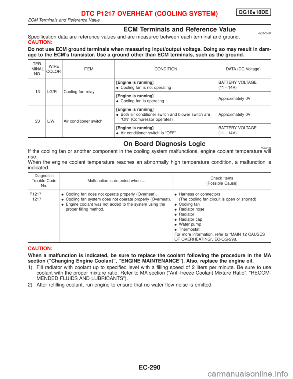
ECM Terminals and Reference Value=NCEC0487Specification data are reference values and are measured between each terminal and ground.
CAUTION:
Do not use ECM ground terminals when measuring input/output voltage. Doing so may result in dam-
age to the ECM's transistor. Use a ground other than ECM terminals, such as the ground.
TER-
MINAL
NO.WIRE
COLORITEM CONDITION DATA (DC Voltage)
13 LG/R Cooling fan relay[Engine is running]
ICooling fan is not operatingBATTERY VOLTAGE
(11 - 14V)
[Engine is running]
ICooling fan is operatingApproximately 0V
23 L/W Air conditioner switch[Engine is running]
IBoth air conditioner switch and blower switch are
ªONº (Compressor operates)Approximately 0V
[Engine is running]
IAir conditioner switch is ªOFFºBATTERY VOLTAGE
(11 - 14V)
On Board Diagnosis LogicNCE0488If the cooling fan or another component in the cooling system malfunctions, engine coolant temperature will
rise.
When the engine coolant temperature reaches an abnormally high temperature condition, a malfunction is
indicated.
Diagnostic
Trouble Code
No.Malfunction is detected when ...Check Items
(Possible Cause)
P1217
1217ICooling fan does not operate properly (Overheat).
ICooling fan system does not operate properly (Overheat).
IEngine coolant was not added to the system using the
proper filling method.IHarness or connectors
(The cooling fan circuit is open or shorted).
ICooling fan
IRadiator hose
IRadiator
IRadiator cap
IWater pump
IThermostat
For more information, refer to ªMAIN 12 CAUSES
OF OVERHEATINGº, EC-QG-298.
CAUTION:
When a malfunction is indicated, be sure to replace the coolant following the procedure in the MA
section (ªChanging Engine Coolantº, ªENGINE MAINTENANCEº). Also, replace the engine oil.
1) Fill radiator with coolant up to specified level with a filling speed of 2 liters per minute. Be sure to use
coolant with the proper mixture ratio. Refer to MA section (ªAnti-freeze Coolant Mixture Ratioº, ªRECOM-
MENDED FLUIDS AND LUBRICANTSº).
2) After refilling coolant, run engine to ensure that no water-flow noise is emitted.
DTC P1217 OVERHEAT (COOLING SYSTEM)QG16I18DE
ECM Terminals and Reference Value
EC-290