1999 NISSAN PRIMERA dimensions
[x] Cancel search: dimensionsPage 117 of 2267
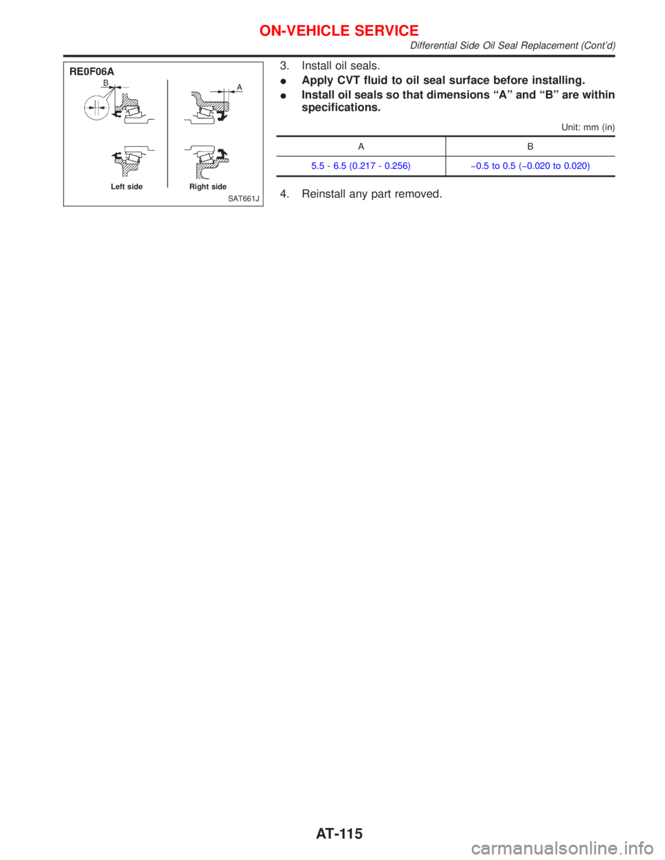
3. Install oil seals.
IApply CVT fluid to oil seal surface before installing.
IInstall oil seals so that dimensions ªAº and ªBº are within
specifications.
Unit: mm (in)
AB
5.5 - 6.5 (0.217 - 0.256) þ0.5 to 0.5 (þ0.020 to 0.020)
4. Reinstall any part removed.SAT661J Left side Right side
ON-VEHICLE SERVICE
Differential Side Oil Seal Replacement (Cont'd)
AT-115
Page 274 of 2267
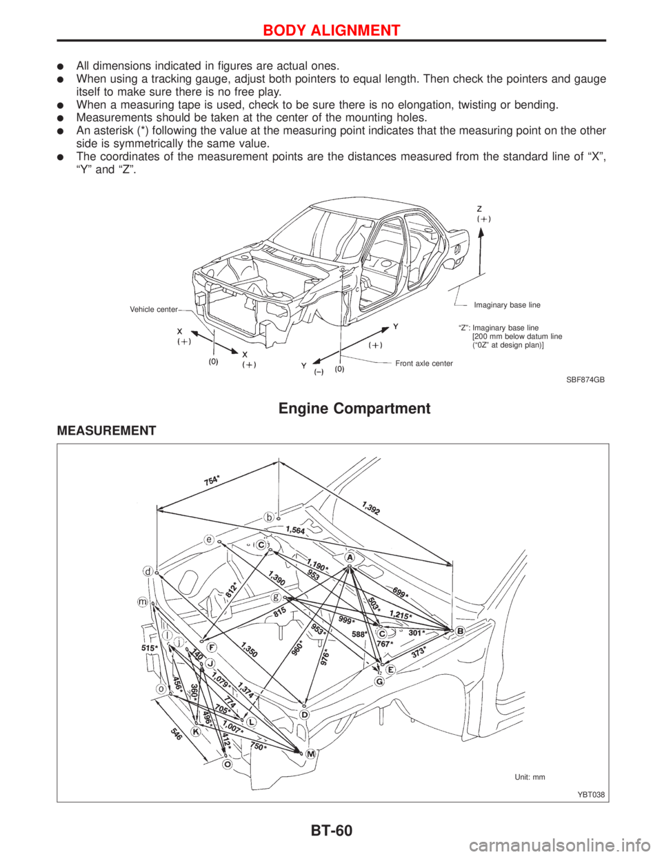
lAll dimensions indicated in figures are actual ones.
lWhen using a tracking gauge, adjust both pointers to equal length. Then check the pointers and gauge
itself to make sure there is no free play.
lWhen a measuring tape is used, check to be sure there is no elongation, twisting or bending.
lMeasurements should be taken at the center of the mounting holes.
lAn asterisk (*) following the value at the measuring point indicates that the measuring point on the other
side is symmetrically the same value.
lThe coordinates of the measurement points are the distances measured from the standard line of ªXº,
ªYº and ªZº.
Engine Compartment
MEASUREMENT
SBF874GB Imaginary base line
Front axle center Vehicle center
ªZº: Imaginary base line
[200 mm below datum line
(ª0Zº at design plan)]
YBT038 Unit: mm
BODY ALIGNMENT
BT-60
Page 1541 of 2267
ENGINE MECHANICAL
SECTION
EM
CONTENTS
PRECAUTIONS...............................................................5
Parts Requiring Angular Tightening .............................5
Liquid Gasket Application Procedure ..........................5
PREPARATION................................................................6
Special Service Tools ..................................................6
Commercial Service Tools .........................................10
QG
NOISE, VIBRATION AND HARSHNESS (NVH)
TROUBLESHOOTING................................................... 11
NVH Troubleshooting - Engine Noise ....................... 11
OUTER COMPONENT PARTS.....................................13
Removal and Installation ...........................................13
MEASUREMENT OF COMPRESSION PRESSURE....16
OIL PAN.........................................................................17
Components...............................................................17
Removal .....................................................................17
Installation ..................................................................18
TIMING CHAIN..............................................................19
Components...............................................................19
Removal .....................................................................20
Inspection...................................................................24
Installation ..................................................................24
OIL SEAL.......................................................................29
Replacement ..............................................................29
VALVE OIL SEAL.....................................................29
FRONT OIL SEAL....................................................29
REAR OIL SEAL......................................................30
CYLINDER HEAD..........................................................31
Components...............................................................31
Removal .....................................................................32
Disassembly...............................................................34
Inspection...................................................................34
CYLINDER HEAD DISTORTION...............................34
CAMSHAFT VISUAL CHECK....................................34
CAMSHAFT RUNOUT..............................................35
CAMSHAFT CAM HEIGHT.......................................35
CAMSHAFT JOURNAL CLEARANCE........................35
CAMSHAFT END PLAY............................................36
CAMSHAFT SPROCKET RUNOUT...........................36
VALVE GUIDE CLEARANCE....................................36
VALVE GUIDE REPLACEMENT................................37
VALVE SEATS.........................................................38
REPLACING VALVE SEAT FOR SERVICE PARTS.....38
VALVE DIMENSIONS...............................................39
VALVE SPRING.......................................................39
VALVE LIFTER AND VALVE SHIM.............................40
Valve Clearance.........................................................40
CHECKING.............................................................40
ADJUSTING............................................................41
Assembly ...................................................................43
Installation ..................................................................43
ENGINE REMOVAL.......................................................48
Removal and Installation ...........................................48
REMOVAL...............................................................49
INSTALLATION........................................................51
CYLINDER BLOCK.......................................................52
Components...............................................................52
Removal and Installation ...........................................53
Disassembly...............................................................53
PISTON AND CRANKSHAFT....................................53
Inspection...................................................................54
PISTON AND PISTON PIN CLEARANCE...................54
PISTON RING SIDE CLEARANCE............................54
PISTON RING END GAP..........................................54
CONNECTING ROD BEND AND TORSION...............55
CYLINDER BLOCK DISTORTION AND WEAR...........55
PISTON-TO-BORE CLEARANCE..............................56
CRANKSHAFT.........................................................57
BEARING CLEARANCE...........................................57
CONNECTING ROD BUSHING CLEARANCE
(Small end)
..............................................................59
REPLACEMENT OF CONNECTING ROD
BUSHING (Small end)
..............................................60
FLYWHEEL/DRIVE PLATE RUNOUT.........................60
EM
Page 1542 of 2267
Assembly ...................................................................60
PISTON..................................................................60
CRANKSHAFT.........................................................61
SR20DE
NOISE, VIBRATION AND HARSHNESS (NVH)
TROUBLESHOOTING........................................64
NVH Troubleshooting - Engine Noise .......................65
OUTER COMPONENT PARTS.....................................66
COMPRESSION PRESSURE........................................69
Measurement of Compression Pressure ...................69
OIL PAN.........................................................................70
Removal .....................................................................70
Installation ..................................................................73
TIMING CHAIN..............................................................75
Components...............................................................75
Removal .....................................................................76
Inspection...................................................................79
Installation ..................................................................79
OIL SEAL REPLACEMENT..........................................84
VALVE OIL SEAL.....................................................84
FRONT OIL SEAL....................................................84
REAR OIL SEAL......................................................85
CYLINDER HEAD..........................................................86
Components...............................................................86
Removal .....................................................................87
Disassembly...............................................................89
Inspection...................................................................91
CYLINDER HEAD DISTORTION...............................91
CAMSHAFT VISUAL CHECK....................................91
CAMSHAFT RUNOUT..............................................92
CAMSHAFT CAM HEIGHT.......................................92
CAMSHAFT JOURNAL CLEARANCE........................92
CAMSHAFT END PLAY............................................93
CAMSHAFT SPROCKET RUNOUT...........................93
VALVE GUIDE CLEARANCE....................................93
VALVE GUIDE REPLACEMENT................................94
VALVE SEATS.........................................................95
REPLACING VALVE SEAT FOR SERVICE PARTS.....95
VALVE DIMENSIONS...............................................95
VALVE SPRING.......................................................96
HYDRAULIC LASH ADJUSTER................................96
ROCKER ARM, SHIM AND ROCKER ARM GUIDE.....97
Assembly ...................................................................97
Installation ..................................................................99
ENGINE REMOVAL.....................................................106
Components.............................................................106
Removal ...................................................................107
Installation ................................................................108
CYLINDER BLOCK.....................................................109
Components.............................................................109
Disassembly............................................................. 110
PISTON AND CRANKSHAFT.................................. 110Inspection................................................................. 110
PISTON AND PISTON PIN CLEARANCE................. 110
PISTON RING SIDE CLEARANCE.......................... 111
PISTON RING END GAP........................................ 111
CONNECTING ROD BEND AND TORSION............. 111
CYLINDER BLOCK DISTORTION AND WEAR......... 112
PISTON-TO-BORE CLEARANCE............................ 112
CRANKSHAFT....................................................... 113
BEARING CLEARANCE......................................... 114
CONNECTING ROD BUSHING CLEARANCE
(Small end)
............................................................ 116
REPLACEMENT OF CONNECTING ROD
BUSHING (Small end)
............................................ 117
REPLACEMENT OF PILOT BUSHING (M/T) OR
PILOT CONVERTER (CVT)
.................................... 117
FLYWHEEL/DRIVE PLATE RUNOUT....................... 117
Assembly ................................................................. 117
PISTON................................................................ 117
CRANKSHAFT....................................................... 118
CD20T
NOISE, VIBRATION AND HARSHNESS (NVH)
TROUBLESHOOTING.....................................121
NVH Troubleshooting Chart - Engine Noise ...........122
OUTER COMPONENT PARTS...................................123
COMPRESSION PRESSURE......................................126
OIL PAN.......................................................................129
Removal ...................................................................129
Installation ................................................................129
TIMING BELT...............................................................131
Camshaft Timing Belt ..............................................131
REMOVAL.............................................................131
Inspection.................................................................133
Installation ................................................................134
Injection Pump Timing Belt ......................................135
REMOVAL.............................................................135
INSTALLATION......................................................136
OIL SEAL REPLACEMENT........................................138
VALVE OIL SEAL...................................................138
CAMSHAFT AND CRANKSHAFT OIL SEAL
INSTALLING DIRECTION AND MANNER
................138
CAMSHAFT OIL SEALS.........................................138
CRANKSHAFT FRONT OIL SEAL...........................139
CRANKSHAFT REAR OIL SEAL.............................139
CYLINDER HEAD........................................................140
Components.............................................................140
Removal ...................................................................141
Disassembly.............................................................141
Inspection.................................................................142
CYLINDER HEAD DISTORTION.............................142
VALVE GUIDE CLEARANCE..................................142
VALVE GUIDE REPLACEMENT..............................142
VALVE SEATS.......................................................143
VALVE SEAT REPLACEMENT................................143
CONTENTS(Cont'd)
EM-2
Page 1543 of 2267
VALVE DIMENSIONS.............................................144
VALVE SPRING SQUARENESS..............................145
VALVE SPRING PRESSURE LOAD........................145
VALVE LIFTER......................................................145
COMBUSTION CHAMBER REPLACEMENT............146
CAMSHAFT VISUAL CHECK..................................147
CAMSHAFT END PLAY..........................................147
CAMSHAFT RUNOUT............................................147
CAMSHAFT CAM HEIGHT.....................................147
CAMSHAFT JOURNAL CLEARANCE......................147
Valve clearance .......................................................148
Checking ..................................................................148
Adjusting ..................................................................149
Assembly .................................................................151
Installation ................................................................151
TURBOCHARGER.......................................................156
Removal ...................................................................156
Disassembly.............................................................157
Inspection.................................................................158
OIL AND WATER TUBES........................................158
ROTOR SHAFT.....................................................158
TURBINE WHEEL..................................................159
COMPRESSOR WHEEL.........................................159
WASTEGATE VALVE..............................................160
WASTEGATE VALVE ACTUATOR...........................160
Assembly .................................................................160
Installation ................................................................160
ENGINE REMOVAL.....................................................162
CYLINDER BLOCK.....................................................166
Components.............................................................166
Preparation ..............................................................167
Disassembly.............................................................167
PISTON AND CRANKSHAFT..................................167
Inspection.................................................................168
PISTON AND PISTON PIN CLEARANCE.................168
PISTON RING SIDE CLEARANCE..........................168
PISTON RING END GAP........................................169
MAIN BEARING CLEARANCE................................169
CONNECTING ROD BEARING CLEARANCE (Big
end)
......................................................................170
CONNECTING ROD AND PISTON PIN
CLEARANCE (Small end)
.......................................171
CONNECTING ROD BEND AND TORSION.............172
CRANKSHAFT.......................................................172
CYLINDER BLOCK DISTORTION...........................173
CYLINDER BORE..................................................173
PISTON-TO-BORE CLEARANCE............................174
Assembly .................................................................175
PISTON................................................................175
CRANKSHAFT.......................................................175
PISTON WITH CONNECTING ROD........................176
FLYWHEEL RUNOUT.............................................177QG
SERVICE DATA AND SPECIFICATIONS (SDS)........178
General Specifications .............................................178
Compression Pressure ............................................178
Cylinder Head ..........................................................178
Valve ........................................................................179
VA LV E...................................................................179
VALVE SPRING.....................................................179
VALVE LIFTER......................................................179
VALVE CLEARANCE..............................................179
VALVE GUIDE.......................................................180
AVAILABLE SHIMS................................................180
VA LV E S E AT.........................................................182
VALVE SEAT RESURFACE LIMIT...........................183
Camshaft and Camshaft Bearing ............................183
Cylinder Block ..........................................................184
Piston, Piston Ring and Piston Pin .........................185
PISTON................................................................185
PISTON RING.......................................................185
PISTON PIN..........................................................185
Connecting Rod .......................................................186
Crankshaft................................................................186
Main Bearing............................................................186
STANDARD...........................................................186
UNDERSIZE..........................................................186
Connecting Rod Bearing .........................................187
STANDARD SIZE...................................................187
UNDERSIZE..........................................................187
Bearing Clearance ...................................................187
Miscellaneous Components.....................................187
SR20DE
SERVICE DATA AND SPECIFICATIONS (SDS)........188
General Specifications .............................................188
Inspection and Adjustment ......................................188
COMPRESSION PRESSURE.................................188
CYLINDER HEAD..................................................188
VA LV E...................................................................189
CAMSHAFT AND CAMSHAFT BEARING.................192
CYLINDER BLOCK................................................192
PISTON, PISTON RING AND PISTON PIN..............193
CONNECTING ROD...............................................193
CRANKSHAFT.......................................................194
AVAILABLE MAIN BEARING...................................194
AVAILABLE CONNECTING ROD BEARING.............195
MISCELLANEOUS COMPONENTS.........................195
CD20T
SERVICE DATA AND SPECIFICATIONS (SDS)........196
General Specifications .............................................196
Inspection and Adjustment ......................................196
COMPRESSION PRESSURE.................................196
CYLINDER HEAD..................................................196
CONTENTS(Cont'd)
EM-3
Page 1550 of 2267
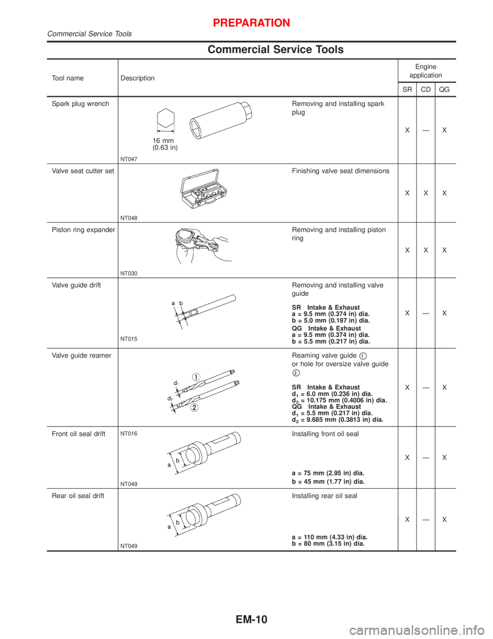
Commercial Service Tools
Tool name DescriptionEngine
application
SR CD QG
Spark plug wrench
NT047
16 mm
(0.63 in)Removing and installing spark
plug
XÐX
Valve seat cutter set
NT048
Finishing valve seat dimensions
XXX
Piston ring expander
NT030
Removing and installing piston
ring
XXX
Valve guide drift
NT015
Removing and installing valve
guide
XÐX
SR Intake & Exhaust
a = 9.5 mm (0.374 in) dia.
b = 5.0 mm (0.197 in) dia.
QG Intake & Exhaust
a = 9.5 mm (0.374 in) dia.
b = 5.5 mm (0.217 in) dia.
Valve guide reamer
NT016
Reaming valve guidep1
or hole for oversize valve guide
p2
XÐXSR Intake & Exhaust
d1= 6.0 mm (0.236 in) dia.
d2= 10.175 mm (0.4006 in) dia.
QG Intake & Exhaust
d
1= 5.5 mm (0.217 in) dia.
d2= 9.685 mm (0.3813 in) dia.
Front oil seal drift
NT049
Installing front oil seal
XÐX
a = 75 mm (2.95 in) dia.
b = 45 mm (1.77 in) dia.
Rear oil seal drift
NT049
Installing rear oil seal
XÐX
a = 110 mm (4.33 in) dia.
b = 80 mm (3.15 in) dia.
PREPARATION
Commercial Service Tools
EM-10
Page 1579 of 2267
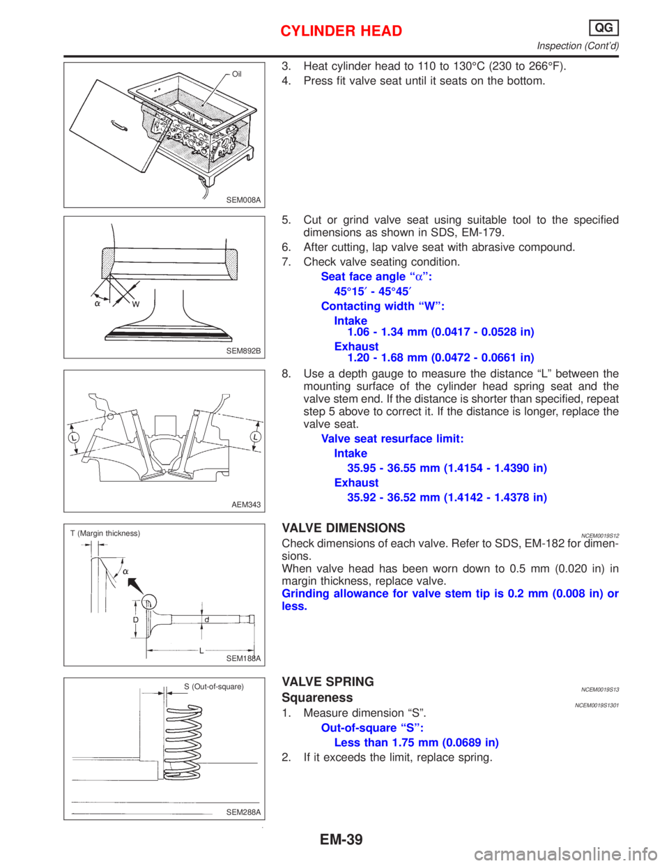
3. Heat cylinder head to 110 to 130ÉC (230 to 266ÉF).
4. Press fit valve seat until it seats on the bottom.
5. Cut or grind valve seat using suitable tool to the specified
dimensions as shown in SDS, EM-179.
6. After cutting, lap valve seat with abrasive compound.
7. Check valve seating condition.
Seat face angle ªaº:
45É15¢- 45É45¢
Contacting width ªWº:
Intake
1.06 - 1.34 mm (0.0417 - 0.0528 in)
Exhaust
1.20 - 1.68 mm (0.0472 - 0.0661 in)
8. Use a depth gauge to measure the distance ªLº between the
mounting surface of the cylinder head spring seat and the
valve stem end. If the distance is shorter than specified, repeat
step 5 above to correct it. If the distance is longer, replace the
valve seat.
Valve seat resurface limit:
Intake
35.95 - 36.55 mm (1.4154 - 1.4390 in)
Exhaust
35.92 - 36.52 mm (1.4142 - 1.4378 in)
VALVE DIMENSIONSNCEM0019S12Check dimensions of each valve. Refer to SDS, EM-182 for dimen-
sions.
When valve head has been worn down to 0.5 mm (0.020 in) in
margin thickness, replace valve.
Grinding allowance for valve stem tip is 0.2 mm (0.008 in) or
less.
VALVE SPRINGNCEM0019S13SquarenessNCEM0019S13011. Measure dimension ªSº.
Out-of-square ªSº:
Less than 1.75 mm (0.0689 in)
2. If it exceeds the limit, replace spring.
SEM008AOil
SEM892B
AEM343
SEM188A T (Margin thickness)
SEM288A S (Out-of-square)
CYLINDER HEADQG
Inspection (Cont'd)
EM-39
Page 1635 of 2267
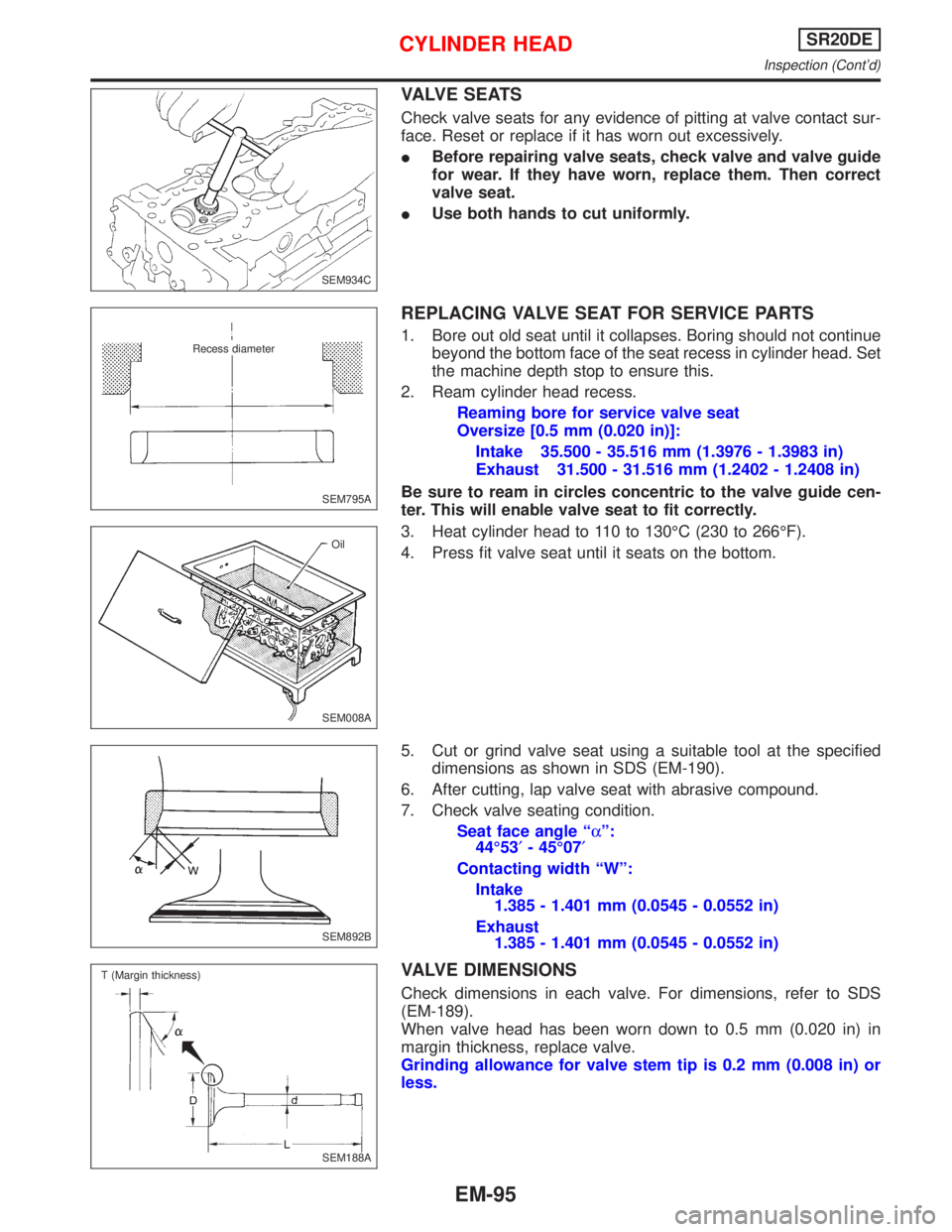
VALVE SEATS
Check valve seats for any evidence of pitting at valve contact sur-
face. Reset or replace if it has worn out excessively.
IBefore repairing valve seats, check valve and valve guide
for wear. If they have worn, replace them. Then correct
valve seat.
IUse both hands to cut uniformly.
REPLACING VALVE SEAT FOR SERVICE PARTS
1. Bore out old seat until it collapses. Boring should not continue
beyond the bottom face of the seat recess in cylinder head. Set
the machine depth stop to ensure this.
2. Ream cylinder head recess.
Reaming bore for service valve seat
Oversize [0.5 mm (0.020 in)]:
Intake 35.500 - 35.516 mm (1.3976 - 1.3983 in)
Exhaust 31.500 - 31.516 mm (1.2402 - 1.2408 in)
Be sure to ream in circles concentric to the valve guide cen-
ter. This will enable valve seat to fit correctly.
3. Heat cylinder head to 110 to 130ÉC (230 to 266ÉF).
4. Press fit valve seat until it seats on the bottom.
5. Cut or grind valve seat using a suitable tool at the specified
dimensions as shown in SDS (EM-190).
6. After cutting, lap valve seat with abrasive compound.
7. Check valve seating condition.
Seat face angle ªaº:
44É53¢- 45É07¢
Contacting width ªWº:
Intake
1.385 - 1.401 mm (0.0545 - 0.0552 in)
Exhaust
1.385 - 1.401 mm (0.0545 - 0.0552 in)
VALVE DIMENSIONS
Check dimensions in each valve. For dimensions, refer to SDS
(EM-189).
When valve head has been worn down to 0.5 mm (0.020 in) in
margin thickness, replace valve.
Grinding allowance for valve stem tip is 0.2 mm (0.008 in) or
less.
SEM934C
SEM795A
.Recess diameter
SEM008AOil
SEM892B
.SEM188A T (Margin thickness)
CYLINDER HEADSR20DE
Inspection (Cont'd)
EM-95