Page 842 of 2267
9 CHECK HEATED OXYGEN SENSOR 1 (FRONT) HARNESS
1. Turn off engine and disconnect battery ground cable.
2. Disconnect ECM harness connector.
3. Disconnect heated oxygen sensor 1 (front) harness connector.
4. Then connect harness connector terminal for heated oxygen sensor 1 (front) to ground with a jumper wire.
MEF031DA5. Check for continuity between terminal 62 of ECM harness connector and body ground.
Continuity exists...OK
Continuity does not exist...NG
OK or NG
OK©1. Connect ECM harness connector to ECM.
2. GO TO 10.
NG©1. Repair or replace harness.
2. GO TO 5. (With CONSULT-II)
3. GO TO 6. (Without CONSULT-II)
Heated oxygen sensor 1 (front)
harness connector
BASIC SERVICE PROCEDURESR20DE
Idle Speed/Ignition Timing/Idle Mixture Ratio Adjustment (Cont'd)
EC-42
Page 1161 of 2267

CAUTION:
�If it becomes necessary to start the engine with a
booster battery and jumper cables, use a 12-volt booster
battery.
�After connecting battery cables, ensure that they are
tightly clamped to battery terminals for good contact.
�Never add distilled water through the hole used to check
specific gravity.
How to Handle Battery
METHODS OF PREVENTING OVER-DISCHARGE
The following precautions must be taken to prevent over-dis-
charging a battery.
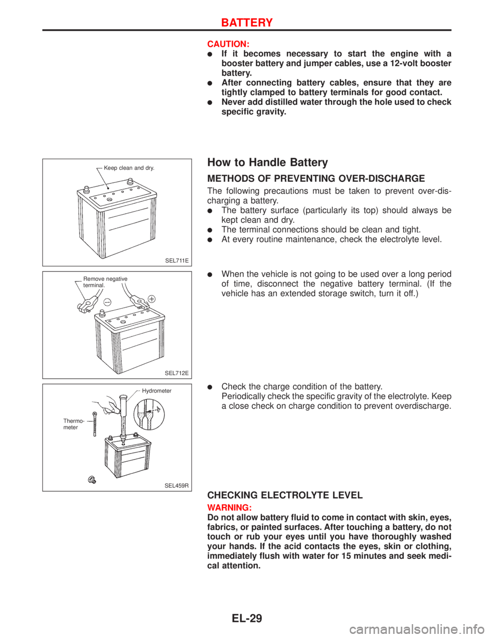
�The battery surface (particularly its top) should always be
kept clean and dry.
�The terminal connections should be clean and tight.
�At every routine maintenance, check the electrolyte level.
�When the vehicle is not going to be used over a long period
of time, disconnect the negative battery terminal. (If the
vehicle has an extended storage switch, turn it off.)
�Check the charge condition of the battery.
Periodically check the specific gravity of the electrolyte. Keep
a close check on charge condition to prevent overdischarge.
CHECKING ELECTROLYTE LEVEL
WARNING:
Do not allow battery fluid to come in contact with skin, eyes,
fabrics, or painted surfaces. After touching a battery, do not
touch or rub your eyes until you have thoroughly washed
your hands. If the acid contacts the eyes, skin or clothing,
immediately flush with water for 15 minutes and seek medi-
cal attention.
SEL711E Keep clean and dry.
SEL712E Remove negative
terminal.
SEL459R Hydrometer
Thermo-
meter
BATTERY
EL-29
Page 1360 of 2267
Inspection
SPEAKER
1. Disconnect speaker harness connector.
2. Measure the resistance between speaker terminals
�1and�2.
�The resistance should be2-4Ω.
3. Using jumper wires, momentarily connect a 9V battery between speaker terminals
�1and�2.
�A momentary hum or pop should be heard.
ANTENNA
Using a jumper wire, clip an auxiliary ground between antenna and body.
�If reception improves, check antenna ground (at body surface).
�If reception does not improve, check main feeder cable for short circuit or open circuit.
RADIO
All voltage inspections are made with:
�Ignition switch ON or ACC
�Radio ON
�Radio connected (If removed for inspection, supply a ground to the case using a jumper wire.)
AUDIO
EL-228
Page 1825 of 2267

Voltage check method
To help in understanding the diagnosis of open circuits please refer to the previous schematic.
In any powered circuit, an open can be found by methodically checking the system for the presence of volt-
age. This is done by switching the DMM to the voltage function.
1. Connect one probe of the DMM to a known good ground.
2. Begin probing at one end of the circuit and work your way to the other end.
3. With SW1 open, probe at SW1 to check for voltage.
voltage; open is further down the circuit than SW1.
no voltage; open is between fuse block and SW1 (point A).
4. Close SW1 and probe at relay.
voltage; open is further down the circuit than the relay.
no voltage; open is between SW1 and relay (point B).
5. Close the relay and probe at the solenoid.
voltage; open is further down the circuit than the solenoid.
no voltage; open is between relay and solenoid (point C).
Any powered circuit can be diagnosed using the approach in the above example.
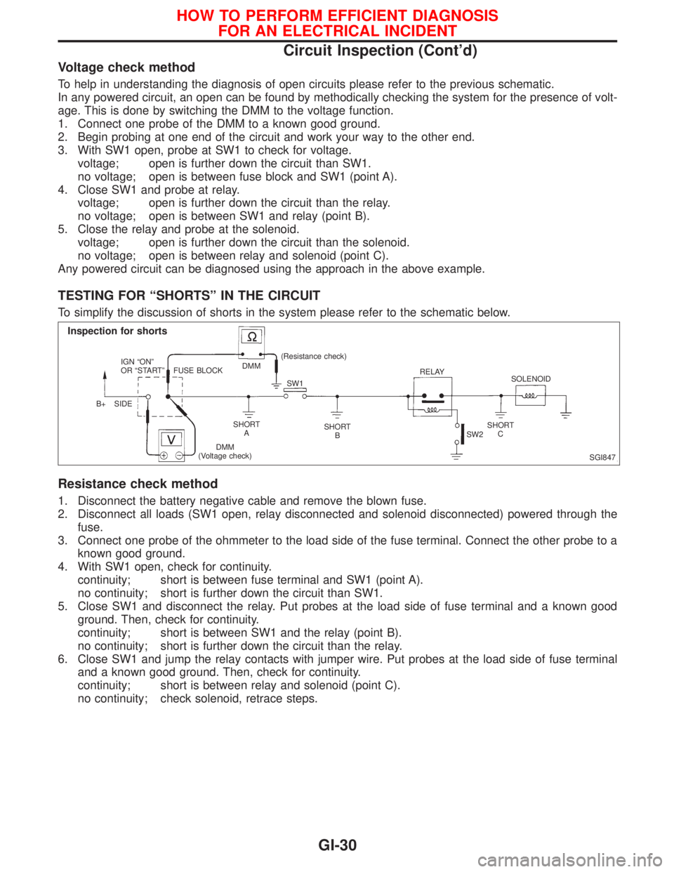
TESTING FOR ªSHORTSº IN THE CIRCUIT
To simplify the discussion of shorts in the system please refer to the schematic below.
Resistance check method
1. Disconnect the battery negative cable and remove the blown fuse.
2. Disconnect all loads (SW1 open, relay disconnected and solenoid disconnected) powered through the
fuse.
3. Connect one probe of the ohmmeter to the load side of the fuse terminal. Connect the other probe to a
known good ground.
4. With SW1 open, check for continuity.
continuity; short is between fuse terminal and SW1 (point A).
no continuity; short is further down the circuit than SW1.
5. Close SW1 and disconnect the relay. Put probes at the load side of fuse terminal and a known good
ground. Then, check for continuity.
continuity; short is between SW1 and the relay (point B).
no continuity; short is further down the circuit than the relay.
6. Close SW1 and jump the relay contacts with jumper wire. Put probes at the load side of fuse terminal
and a known good ground. Then, check for continuity.
continuity; short is between relay and solenoid (point C).
no continuity; check solenoid, retrace steps.
SGI847
Inspection for shorts
IGN ªONº
OR ªSTARTº
B+ SIDEFUSE BLOCKDMM(Resistance check)
SW1RELAY
SOLENOID
SHORT
ASHORT
BSHORT
C
DMM
(Voltage check)SW2
HOW TO PERFORM EFFICIENT DIAGNOSIS
FOR AN ELECTRICAL INCIDENT
Circuit Inspection (Cont'd)
GI-30