1999 NISSAN PRIMERA p0325
[x] Cancel search: p0325Page 445 of 2267
DTC Confirmation Procedure ..................................167
Wiring Diagram ........................................................168
Diagnostic Procedure ..............................................169
Component Inspection .............................................170
DTC P0137 HEATED OXYGEN SENSOR 2
(REAR) (MIN. VOLTAGE MONITORING)...................171
Component Description ...........................................171
CONSULT-II Reference Value in Data Monitor
Mode ........................................................................171
ECM Terminals and Reference Value .....................171
On Board Diagnosis Logic.......................................171
DTC Confirmation Procedure ..................................172
Overall Function Check ...........................................173
Wiring Diagram ........................................................174
Diagnostic Procedure ..............................................175
Component Inspection .............................................178
DTC P0138 HEATED OXYGEN SENSOR 2
(REAR) (MAX. VOLTAGE MONITORING).................180
Component Description ...........................................180
CONSULT-II Reference Value in Data Monitor
Mode ........................................................................180
ECM Terminals and Reference Value .....................180
On Board Diagnosis Logic.......................................180
DTC Confirmation Procedure ..................................181
Overall Function Check ...........................................182
Wiring Diagram ........................................................183
Diagnostic Procedure ..............................................184
Component Inspection .............................................186
DTC P0139 HEATED OXYGEN SENSOR 2
(REAR) (RESPONSE MONITORING).........................188
Component Description ...........................................188
CONSULT-II Reference Value in Data Monitor
Mode ........................................................................188
ECM Terminals and Reference Value .....................188
On Board Diagnosis Logic.......................................188
DTC Confirmation Procedure ..................................189
Overall Function Check ...........................................190
Wiring Diagram ........................................................191
Diagnostic Procedure ..............................................192
Component Inspection .............................................195
DTC P0140 HEATED OXYGEN SENSOR 2
(REAR) (HIGH VOLTAGE)..........................................197
Component Description ...........................................197
CONSULT-II Reference Value in Data Monitor
Mode ........................................................................197
ECM Terminals and Reference Value .....................197
On Board Diagnosis Logic.......................................197
DTC Confirmation Procedure ..................................198
Overall Function Check ...........................................198
Wiring Diagram ........................................................199
Diagnostic Procedure ..............................................200
Component Inspection .............................................201DTC P0141 HEATED OXYGEN SENSOR 2
HEATER (REAR).........................................................203
Description ...............................................................203
CONSULT-II Reference Value in Data Monitor
Mode ........................................................................203
ECM Terminals and Reference Value .....................203
On Board Diagnosis Logic.......................................204
DTC Confirmation Procedure ..................................204
Wiring Diagram ........................................................205
Diagnostic Procedure ..............................................206
Component Inspection .............................................207
DTC P0171 FUEL INJECTION SYSTEM
FUNCTION (LEAN SIDE)............................................208
On Board Diagnosis Logic.......................................208
DTC Confirmation Procedure ..................................208
Wiring Diagram ........................................................210
Diagnostic Procedure .............................................. 211
DTC P0172 FUEL INJECTION SYSTEM
FUNCTION (RICH SIDE).............................................215
On Board Diagnosis Logic.......................................215
DTC Confirmation Procedure ..................................215
Wiring Diagram ........................................................217
Diagnostic Procedure ..............................................218
DTC P0300 - P0304 NO.4-1CYLINDER
MISFIRE, MULTIPLE CYLINDER MISFIRE................222
On Board Diagnosis Logic.......................................222
DTC Confirmation Procedure ..................................222
Diagnostic Procedure ..............................................223
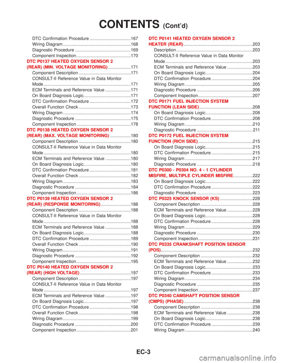
DTC P0325 KNOCK SENSOR (KS)...........................228
Component Description ...........................................228
ECM Terminals and Reference Value .....................228
On Board Diagnosis Logic.......................................228
DTC Confirmation Procedure ..................................228
Wiring Diagram ........................................................229
Diagnostic Procedure ..............................................230
Component Inspection .............................................231
DTC P0335 CRANKSHAFT POSITION SENSOR
(POS)............................................................................232
Component Description ...........................................232
ECM Terminals and Reference Value .....................232
On Board Diagnosis Logic.......................................233
DTC Confirmation Procedure ..................................233
Wiring Diagram ........................................................234
Diagnostic Procedure ..............................................235
Component Inspection .............................................237
DTC P0340 CAMSHAFT POSITION SENSOR
(CMPS) (PHASE).........................................................238
Component Description ...........................................238
ECM Terminals and Reference Value .....................238
On Board Diagnosis Logic.......................................238
DTC Confirmation Procedure ..................................239
Wiring Diagram ........................................................240
CONTENTS(Cont'd)
EC-3
Page 448 of 2267
Alphabetical & P No. Index for DTCNCEC0001ALPHABETICAL INDEX FOR DTCNCEC0001S01
Items
(CONSULT-II screen terms)DTC*5
Reference page
CONSULT-II
GST*2ECM*1
Unable to access ECM Ð Ð EC-QG-81
AIR TEMP SEN/CIRC*6 P0110 0110 EC-QG-116
CMP SEN/CIRCUIT P0340 0340 EC-QG-238
COOLANT T SEN/CIRC*3 P0115 0115 EC-QG-120
CKP SEN/CIRCUIT*6 P0335 0335 EC-QG-232
CYL 1 MISFIRE*6 P0301 0301 EC-QG-222
CYL 2 MISFIRE*6 P0302 0302 EC-QG-222
CYL 3 MISFIRE*6 P0303 0303 EC-QG-222
CYL 4 MISFIRE*6 P0304 0304 EC-QG-222
ECM*6 P0605 0605 EC-QG-282
EGR SYSTEM*6*7 P0400 0400 EC-QG-244
EGR SYSTEM*6*7 P1402 1402 EC-QG-305
EGR TEMP SEN/CIRC*6*7 P1401 1401 EC-QG-300
EGR VOL CON/V CIR*6*7 P0403 0403 EC-QG-252
ENG OVER TEMP P1217 P1217 EC-QG-289
HO2S1 HTR (B1)*6 P0135 0135 EC-QG-166
HO2S1 (B1)*6 P0130 0130 EC-QG-132
HO2S1 (B1)*6 P0131 0131 EC-QG-139
HO2S1 (B1)*6 P0132 0132 EC-QG-145
HO2S1 (B1)*6 P0133 0133 EC-QG-151
HO2S1 (B1)*6 P0134 0134 EC-QG-160
HO2S2 (B1)*6 P0137 0137 EC-QG-171
HO2S2 (B1)*6 P0138 0138 EC-QG-180
HO2S2 (B1)*6 P0139 0139 EC-QG-188
HO2S2 (B1)*6 P0140 0140 EC-QG-197
HO2S2 HTR (B1)*6 P0141 0141 EC-QG-203
FUEL SYS-LEAN/BK1*6 P0171 0171 EC-QG-208
FUEL SYS-RIGH/BK1*6 P0172 0172 EC-QG-215
IACV/AAC VLV/CIRC*6 P0505 0505 EC-QG-274
INT/V TIM V/CIR-B1*6 P1111 1111EC-QG-284
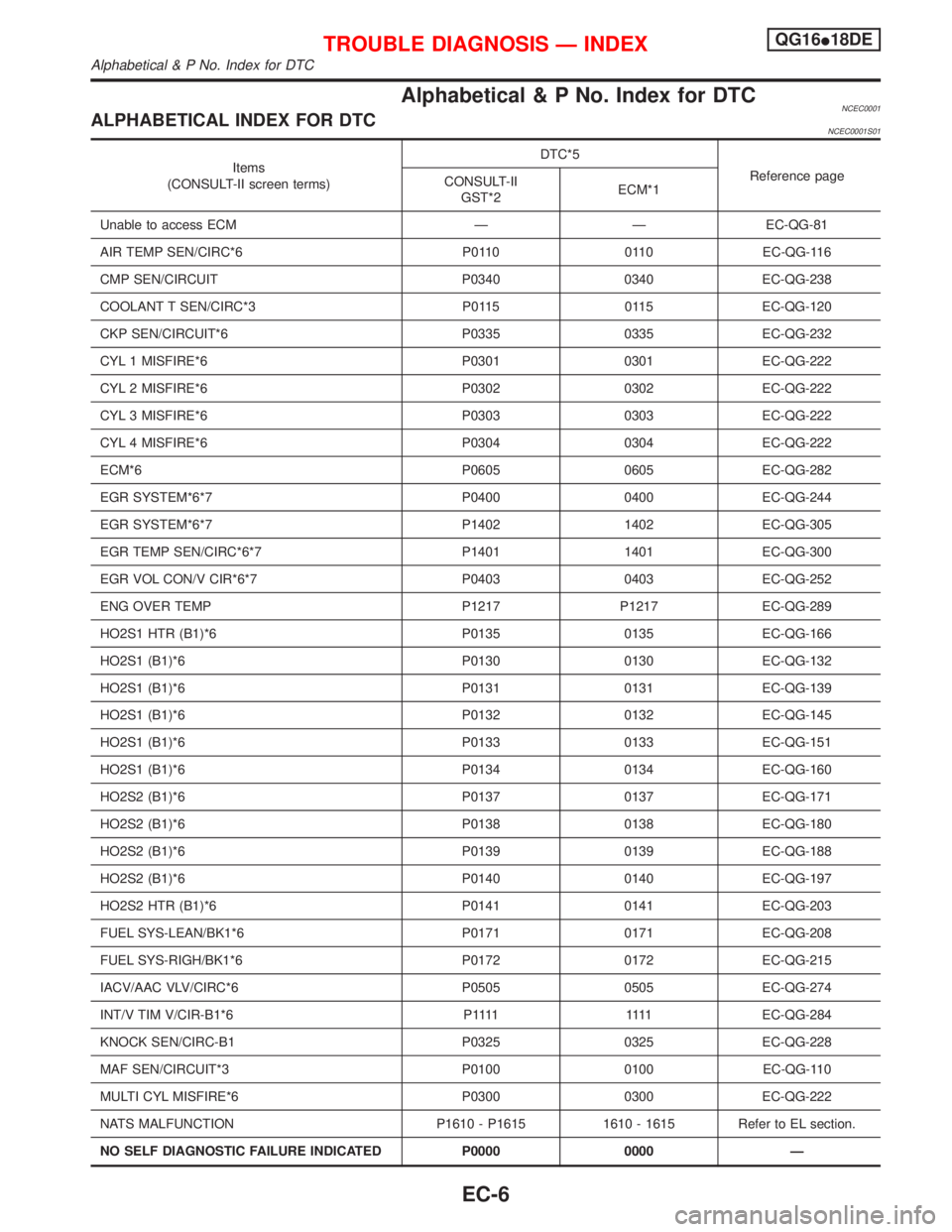
KNOCK SEN/CIRC-B1 P0325 0325 EC-QG-228
MAF SEN/CIRCUIT*3 P0100 0100 EC-QG-110
MULTI CYL MISFIRE*6 P0300 0300 EC-QG-222
NATS MALFUNCTION P1610 - P1615 1610 - 1615 Refer to EL section.
NO SELF DIAGNOSTIC FAILURE INDICATED P0000 0000 Ð
TROUBLE DIAGNOSIS Ð INDEXQG16I18DE
Alphabetical & P No. Index for DTC
EC-6
Page 450 of 2267
DTC*5
Items
(CONSULT-II screen terms)Reference page
CONSULT-II
GST*2ECM*1
P0302 0302 CYL 2 MISFIRE*6 EC-QG-222
P0303 0303 CYL 3 MISFIRE*6 EC-QG-222
P0304 0304 CYL 4 MISFIRE*6 EC-QG-222
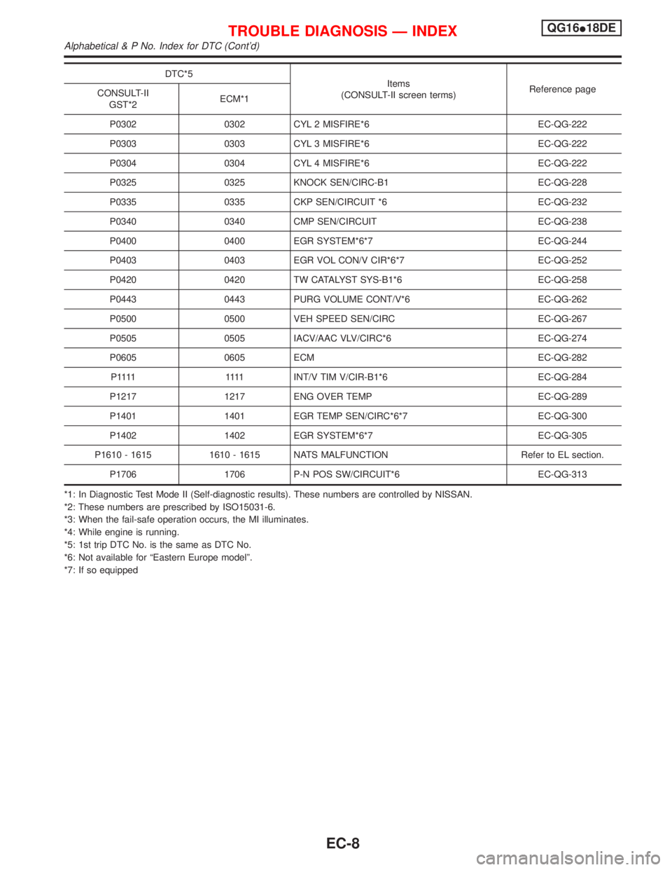
P0325 0325 KNOCK SEN/CIRC-B1 EC-QG-228
P0335 0335 CKP SEN/CIRCUIT *6 EC-QG-232
P0340 0340 CMP SEN/CIRCUIT EC-QG-238
P0400 0400 EGR SYSTEM*6*7 EC-QG-244
P0403 0403 EGR VOL CON/V CIR*6*7 EC-QG-252
P0420 0420 TW CATALYST SYS-B1*6 EC-QG-258
P0443 0443 PURG VOLUME CONT/V*6 EC-QG-262
P0500 0500 VEH SPEED SEN/CIRC EC-QG-267
P0505 0505 IACV/AAC VLV/CIRC*6 EC-QG-274
P0605 0605 ECM EC-QG-282
P 1111 1111INT/V TIM V/CIR-B1*6 EC-QG-284
P1217 1217 ENG OVER TEMP EC-QG-289
P1401 1401 EGR TEMP SEN/CIRC*6*7 EC-QG-300
P1402 1402 EGR SYSTEM*6*7 EC-QG-305
P1610 - 1615 1610 - 1615 NATS MALFUNCTION Refer to EL section.
P1706 1706 P-N POS SW/CIRCUIT*6 EC-QG-313
*1: In Diagnostic Test Mode II (Self-diagnostic results). These numbers are controlled by NISSAN.
*2: These numbers are prescribed by ISO15031-6.
*3: When the fail-safe operation occurs, the MI illuminates.
*4: While engine is running.
*5: 1st trip DTC No. is the same as DTC No.
*6: Not available for ªEastern Europe modelº.
*7: If so equipped
TROUBLE DIAGNOSIS Ð INDEXQG16I18DE
Alphabetical & P No. Index for DTC (Cont'd)
EC-8
Page 485 of 2267
Items
(CONSULT-II screen terms)DTC*4
SRT codeTest value/Test
limit
(GST only)1st trip DTC*4Reference
page CONSULT-II
GST*2ECM*1
HO2S2 (B1)*5 P0140 0140 X X X*3 EC-QG-197
HO2S2 HTR (B1)*5 P0141 0141 X X X*3 EC-QG-203
FUEL SYS LEAN/BK1*5 P0171 0171 Ð Ð X EC-QG-208
FUEL SYS RICH/BK1*5 P0172 0172 Ð Ð X EC-QG-215
MULTI CYL MISFIRE*5 P0300 0300 Ð Ð X EC-QG-222
CYL 1 MISFIRE*5 P0301 0301 Ð Ð X EC-QG-222
CYL 2 MISFIRE*5 P0302 0302 Ð Ð X EC-QG-222
CYL 3 MISFIRE*5 P0303 0303 Ð Ð X EC-QG-222
CYL 4 MISFIRE*5 P0304 0304 Ð Ð X EC-QG-222
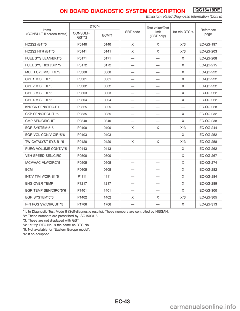
KNOCK SEN/CIRC-B1 P0325 0325 Ð Ð Ð EC-QG-228
CKP SEN/CIRCUIT *5 P0335 0335 Ð Ð X EC-QG-232
CMP SEN/CIRCUIT P0340 0340 Ð Ð X EC-QG-238
EGR SYSTEM*5*6 P0400 0400 X X X*3 EC-QG-244
EGR VOL CON/V CIR*5*6 P0403 0403 Ð Ð X EC-QG-252
TW CATALYST SYS-B1*5 P0420 0420 X X X*3 EC-QG-258
PURG VOLUME CONT/V*5 P0443 0443 Ð Ð X EC-QG-262
VEH SPEED SEN/CIRC P0500 0500 Ð Ð X EC-QG-267
IACV/AAC VLV/CIRC*5 P0505 0505 Ð Ð X EC-QG-274
ECM P0605 0605 Ð Ð X EC-QG-282
INT/V TIM V/CIR-B1*5 P1111 1111 Ð Ð XEC-QG-284
ENG OVER TEMP P1217 1217 Ð Ð X EC-QG-289
EGR TEMP SEN/CIRC*5*6 P1401 1401 Ð Ð X EC-QG-300
EGR SYSTEM*5*6 P1402 1402 X X X*3 EC-QG-305
P-N POS SW/CIRCUIT*5 P1706 1706 Ð Ð X EC-QG-313
*1: In Diagnostic Test Mode II (Self-diagnostic results). These numbers are controlled by NISSAN.
*2: These numbers are prescribed by ISO15031-6.
*3: These are not displayed with GST.
*4: 1st trip DTC No. is the same as DTC No.
*5: Not available for ªEastern Europe modelº.
*6: If so equipped
ON BOARD DIAGNOSTIC SYSTEM DESCRIPTIONQG16I18DE
Emission-related Diagnostic Information (Cont'd)
EC-43
Page 522 of 2267
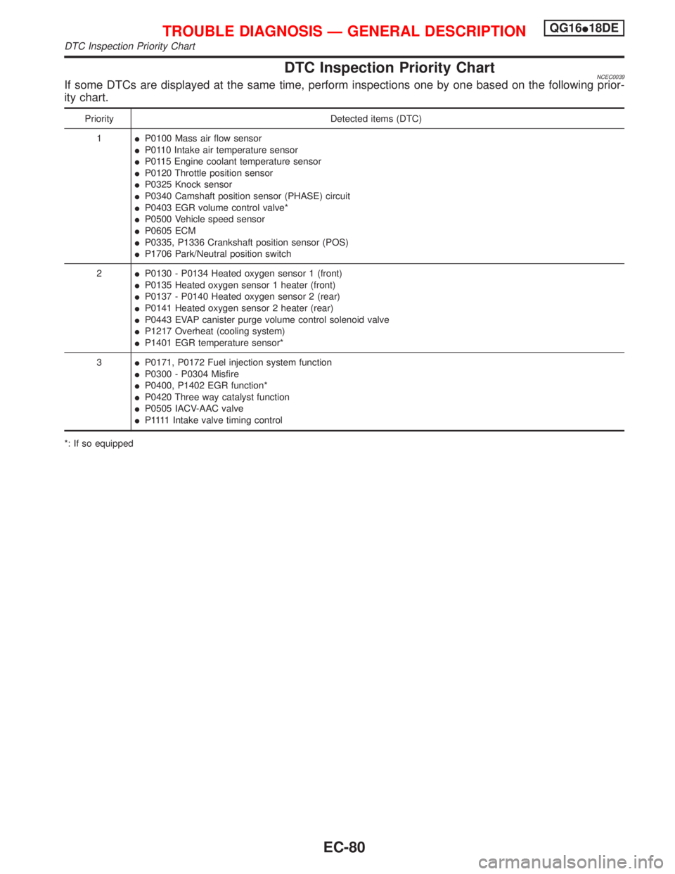
DTC Inspection Priority ChartNCEC0039If some DTCs are displayed at the same time, perform inspections one by one based on the following prior-
ity chart.
Priority Detected items (DTC)
1IP0100 Mass air flow sensor
IP0110 Intake air temperature sensor
IP0115 Engine coolant temperature sensor
IP0120 Throttle position sensor
IP0325 Knock sensor
IP0340 Camshaft position sensor (PHASE) circuit
IP0403 EGR volume control valve*
IP0500 Vehicle speed sensor
IP0605 ECM
IP0335, P1336 Crankshaft position sensor (POS)
IP1706 Park/Neutral position switch
2IP0130 - P0134 Heated oxygen sensor 1 (front)
IP0135 Heated oxygen sensor 1 heater (front)
IP0137 - P0140 Heated oxygen sensor 2 (rear)
IP0141 Heated oxygen sensor 2 heater (rear)
IP0443 EVAP canister purge volume control solenoid valve
IP1217 Overheat (cooling system)
IP1401 EGR temperature sensor*
3IP0171, P0172 Fuel injection system function
IP0300 - P0304 Misfire
IP0400, P1402 EGR function*
IP0420 Three way catalyst function
IP0505 IACV-AAC valve
IP 1111Intake valve timing control
*: If so equipped
TROUBLE DIAGNOSIS Ð GENERAL DESCRIPTIONQG16I18DE
DTC Inspection Priority Chart
EC-80
Page 670 of 2267
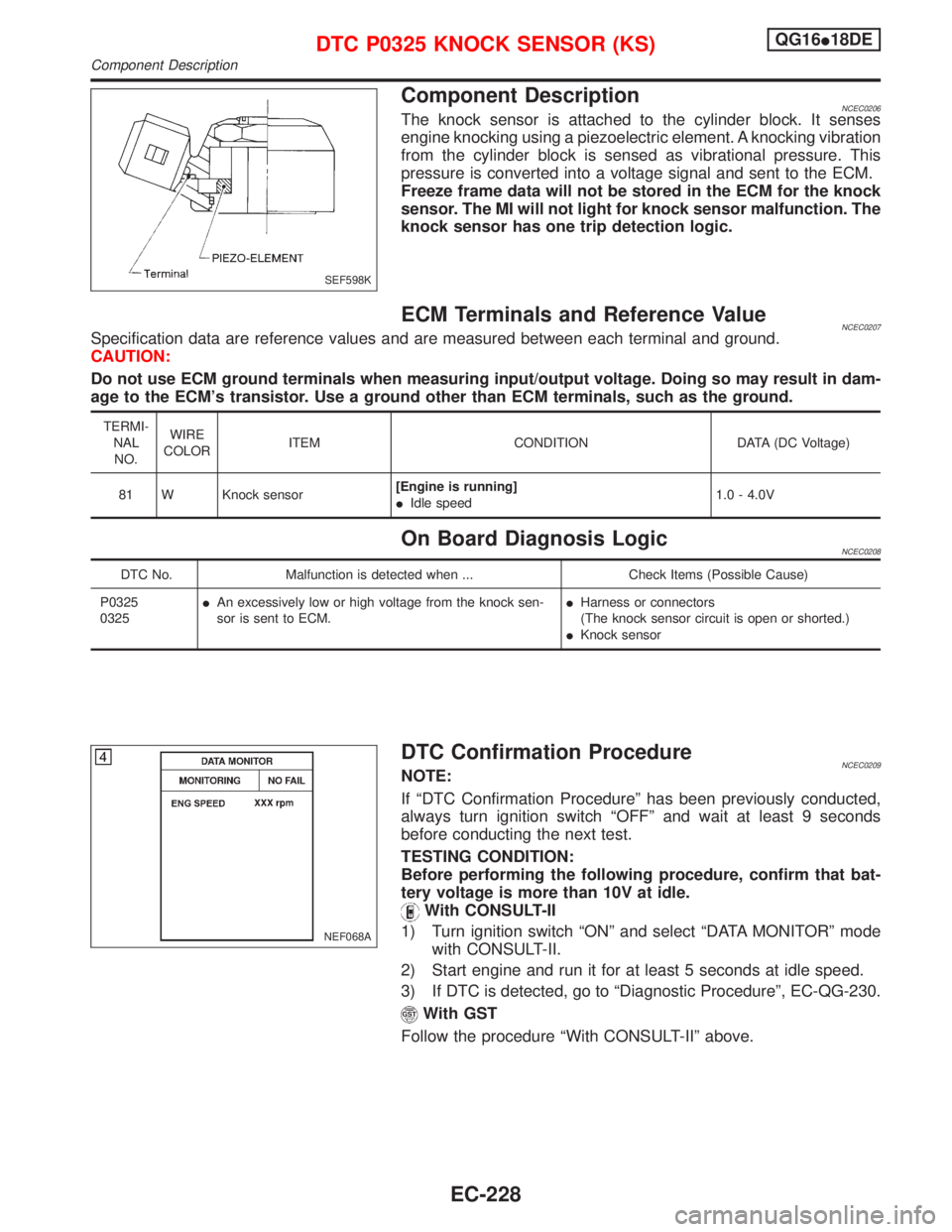
Component DescriptionNCEC0206The knock sensor is attached to the cylinder block. It senses
engine knocking using a piezoelectric element. A knocking vibration
from the cylinder block is sensed as vibrational pressure. This
pressure is converted into a voltage signal and sent to the ECM.
Freeze frame data will not be stored in the ECM for the knock
sensor. The MI will not light for knock sensor malfunction. The
knock sensor has one trip detection logic.
ECM Terminals and Reference ValueNCEC0207Specification data are reference values and are measured between each terminal and ground.
CAUTION:
Do not use ECM ground terminals when measuring input/output voltage. Doing so may result in dam-
age to the ECM's transistor. Use a ground other than ECM terminals, such as the ground.
TERMI-
NAL
NO.WIRE
COLORITEM CONDITION DATA (DC Voltage)
81 W Knock sensor[Engine is running]
IIdle speed1.0 - 4.0V
On Board Diagnosis LogicNCEC0208
DTC No. Malfunction is detected when ... Check Items (Possible Cause)
P0325
0325IAn excessively low or high voltage from the knock sen-
sor is sent to ECM.IHarness or connectors
(The knock sensor circuit is open or shorted.)
IKnock sensor
DTC Confirmation ProcedureNCEC0209NOTE:
If ªDTC Confirmation Procedureº has been previously conducted,
always turn ignition switch ªOFFº and wait at least 9 seconds
before conducting the next test.
TESTING CONDITION:
Before performing the following procedure, confirm that bat-
tery voltage is more than 10V at idle.
With CONSULT-II
1) Turn ignition switch ªONº and select ªDATA MONITORº mode
with CONSULT-II.
2) Start engine and run it for at least 5 seconds at idle speed.
3) If DTC is detected, go to ªDiagnostic Procedureº, EC-QG-230.
With GST
Follow the procedure ªWith CONSULT-IIº above.
SEF598K
NEF068A
DTC P0325 KNOCK SENSOR (KS)QG16I18DE
Component Description
EC-228
Page 671 of 2267
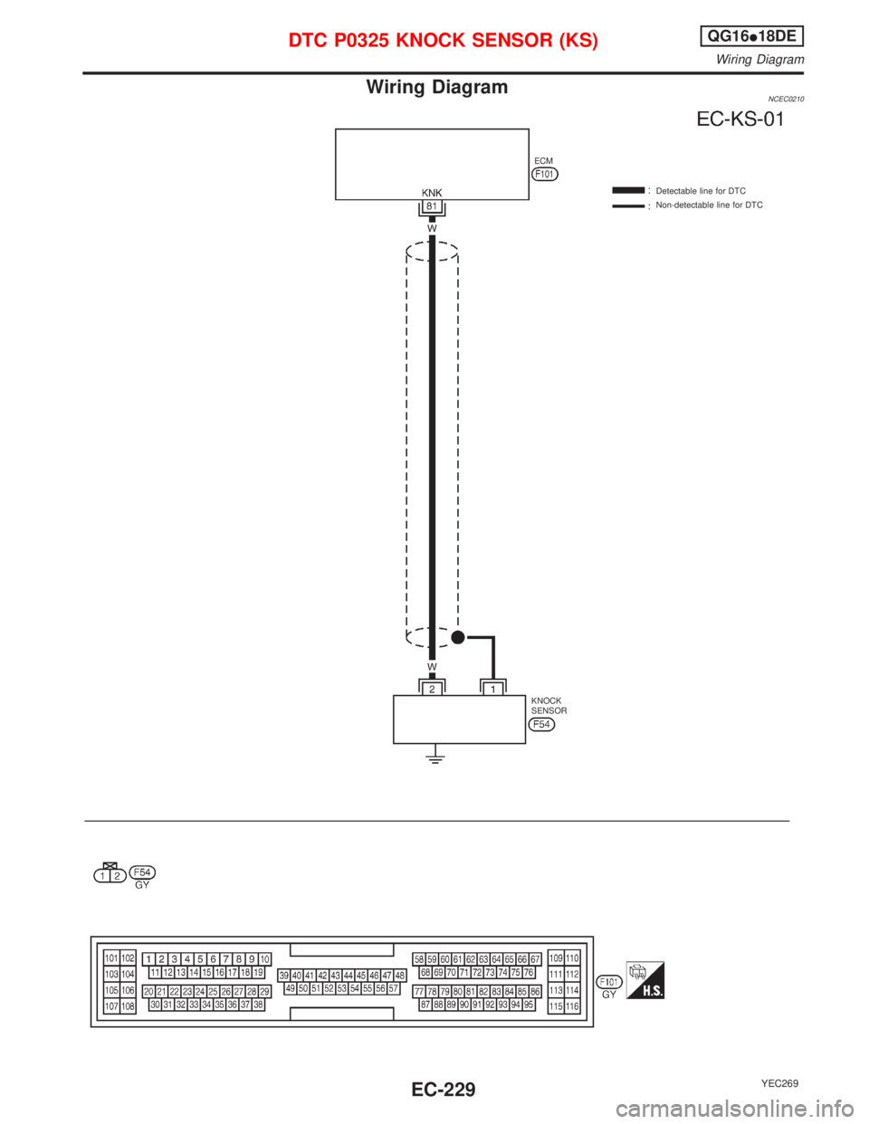
Wiring DiagramNCEC0210
YEC269
Detectable line for DTC
Non-detectable line for DTC ECM
KNOCK
SENSOR
DTC P0325 KNOCK SENSOR (KS)QG16I18DE
Wiring Diagram
EC-229
Page 672 of 2267
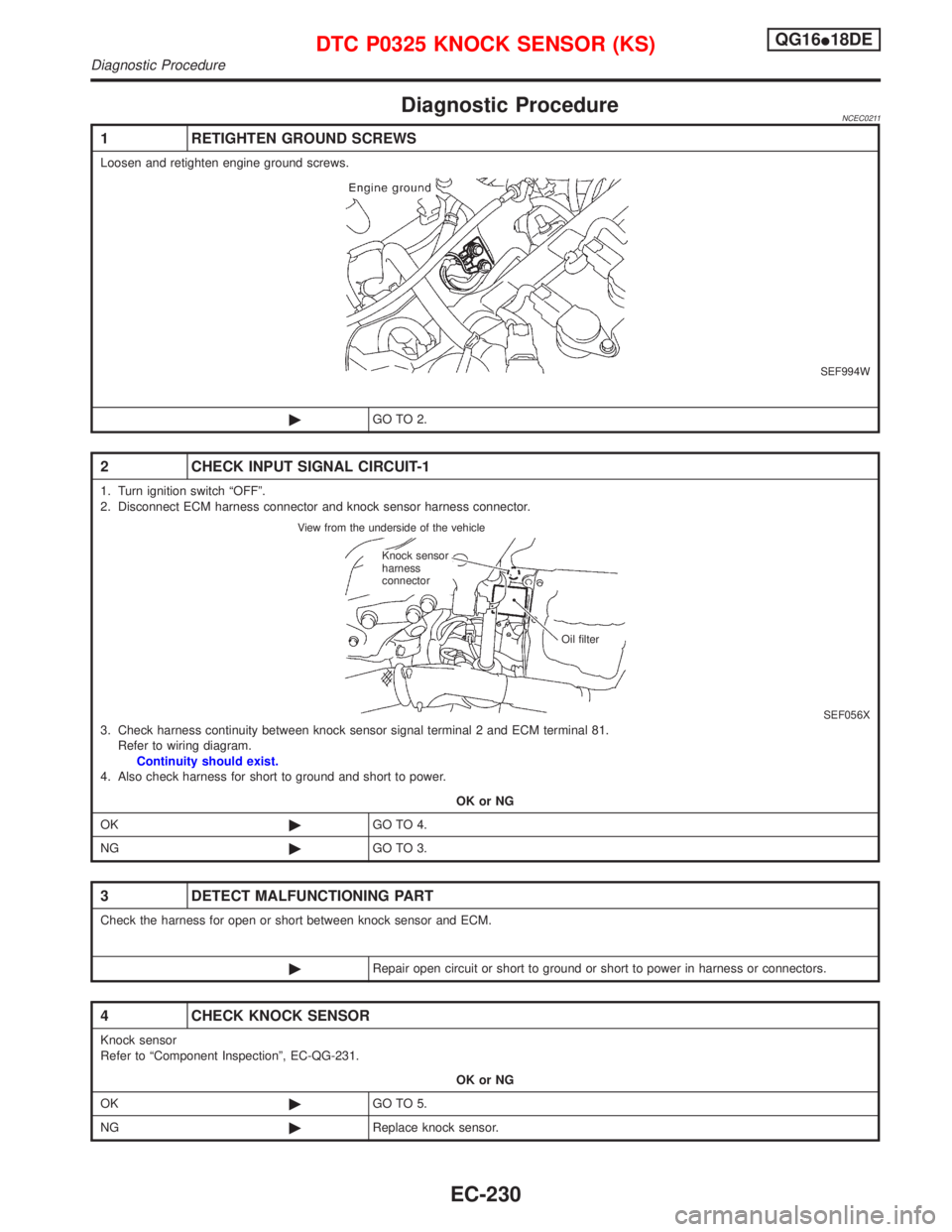
Diagnostic ProcedureNCEC0211
1 RETIGHTEN GROUND SCREWS
Loosen and retighten engine ground screws.
SEF994W
©GO TO 2.
2 CHECK INPUT SIGNAL CIRCUIT-1
1. Turn ignition switch ªOFFº.
2. Disconnect ECM harness connector and knock sensor harness connector.
SEF056X3. Check harness continuity between knock sensor signal terminal 2 and ECM terminal 81.
Refer to wiring diagram.
Continuity should exist.
4. Also check harness for short to ground and short to power.
OK or NG
OK©GO TO 4.
NG©GO TO 3.
3 DETECT MALFUNCTIONING PART
Check the harness for open or short between knock sensor and ECM.
©Repair open circuit or short to ground or short to power in harness or connectors.
4 CHECK KNOCK SENSOR
Knock sensor
Refer to ªComponent Inspectionº, EC-QG-231.
OK or NG
OK©GO TO 5.
NG©Replace knock sensor.
View from the underside of the vehicle
Knock sensor
harness
connector
Oil filter
DTC P0325 KNOCK SENSOR (KS)QG16I18DE
Diagnostic Procedure
EC-230